WARNING : To reduce the risk of injury, user must read this manual before assembling, opera ng
and maintaining this unit, You are responsible for opera
ng the product properly & safely.
Version: V1.20170921
2000W DIGITAL INVERTER GENERATOR

2
WARNING!
Read the following instructions before using the product!
These instructions below are for your safety. Please read through them
thoroughly before use and retain them for future reference. Familiarize yourself
with them to reduce hazards like personal injuries and damage to property.
TABLE OF CONTENTS
Safety Rules.………………….…………………………………………………………………………2
Product Specifications.……….…………………………………………………………………….7
Know Your Inverter Generator…………………………………………………………….……8
Generator Preparation……….…..……………………………………………………….………12
Starting The Generator…………………………………………………………………………….14
Stopping The Generator…………………………………………………………………………..16
Subsequent Starting Of The Generator………………………………………………………..17
Using The Generator………………………………………………………………………………….…….19
Maintenance……………….…………………………………………………………………………..23
Storage……………….……………………………………………………………………………………31
Troubleshooting …………………….……………………………………………………………….33
Wiring Diagram……………….…….……………………………………………………………….35
A112001 Exploded View & Part List……………………………………………….………..36
A112002 Exploded View & Part List……………………………………………….………..41
SAFETY RULES
Read and observe all warnings,
cautions, and instructions on the
generator and in
this owner’s manual
before operating your generator.
NOTE: The following safety
information is not meant to cover all
possible conditions and situations that
may occur. Read the entire Owner’s
Manual for safety and operating
instructions. Failure to follow
instructions and safety information
could result in serious injury or death.
This safety alert symbol is used to
identify safety information about
hazards that can result in personal
injury.
A signal word (DANGER,
WARNING, or CAUTION) is used with
the alert symbol to indicate the
likelihood and the potential severity
of injury. In addition, a hazard symbol
may be used to represent the type of
hazard.
DANGER indicates a hazard, which,
if not avoided, will result in death or
serious injury.

3
WARNING indicates a hazard, which,
if not avoided, could result in death or
serious injury.
CAUTION indicates a hazard, which,
if not avoided, might result in minor
or moderate injury.
CAUTION when used without the
alert symbol, indicates a situation that
could result in damage to the engine
or generator.
DANGER:
CARBON MONOXIDE
Using a generator indoors CAN KILL YOU
IN MINUTES.
Generator exhaust contains high levels
of carbon monoxide (CO), a poisonous
gas you cannot see or smell. If you can
smell the generator exhaust you are
breathing CO. But even if you cannot
smell the exhaust, you could be
breathing CO.
NEVER use a generator inside houses,
garages, crawlspaces, or other partly
enclosed areas. Deadly levels of carbon
monoxide can build up in these areas.
Using a fan or opening windows and
doors does NOT supply enough fresh air.
ONLY use a generator outdoors and far
away from open windows, doors, and
vents. These openings can pull in
generator exhaust.
Even if you use a generator correctly, CO
may leak into the house. ALWAYS use a
battery-powered or battery-backup CO
alarm in your house.
If you start to feel sick, dizzy, or weak
after the generator has been running,
move to fresh air RIGHT AWAY. See
a doctor. You could have carbon
monoxide poisoning."
WARNING:This generator
may emit highly flammable and
explosive gasoline vapors, which can
cause severe burns or even death if
ignited. A nearby open flame can lead to
explosion even if it isn’t directly in
contact with gasoline.
Do not operate near open flame.
Do not smoke near generator.
Always operate on a firm, level
surface.
Always turn generator off before
refueling. Allow generator to cool for at
least 2 minutes before removing fuel
cap. Loosen cap slowly to relieve
pressure in tank.
Do not overfill fuel tank. Gasoline
may expand during operation. Do not
fill to the top of the tank. Allow for
expansion.
Always check for spilled fuel before
operating.
Empty fuel tank before storing or
transporting the generator.
WARNING: This generator
produces powerful voltage, which can
result in electrocution.
ALWAYS ground the generator
before using it (see the “Ground the
Generator” portion of the “GENERATOR
PREPARATION” section).
Generator should only be plugged
into electrical devices, either directly or
with an extension cord. NEVER
connect to a building electrical system

4
without a qualified electrician. Such
connections must comply with local
electrical laws and codes. Failure to
comply can create a back-feed, which
may result in serious injury or death to
utility workers.
Use a ground fault circuit interrupter
(GFCI) in highly conductive areas such
as metal decking or steel work. GFCIs
are available in-line with some
extension cords.
Do not use in rainy conditions.
Do not touch bare wires or
receptacles (outlets).
Do not allow children or
non-qualified persons to operate.
WARNING: This generator
produces heat when running.
Temperatures near exhaust can exceed
150°F (65° C).
Do not touch hot surfaces. Pay
attention to warning labels on the
generator identifying hot parts of the
machine.
Allow generator to cool down after use
before touching engine or areas of the
generator that become hot during use.
CAUTION: Misuse of this generator
can damage it or shorten its life.
Only use generator for its intended
purposes.
Operate only on dry, level surfaces.
Allow generator to run for several
minutes before connecting electrical
devices.
Shut off and disconnect any
malfunctioning devices from
generator.
Do not exceed the wattage capacity of
the generator by plugging in more
electrical devices than the unit can
handle.
Do not turn on electrical devices until
after they are connected to the
generator.
Turn off all connected electrical
devices before stopping the generator.
Turn the engine switch to “OFF”
position when the engine is not
running.
IMPORTANT SAFETY
INSTRUCTIONS
SAVE THESE INSTRUCTIONS - This
manual contains important instructions
for the AAVIX 2000W inverter generator
that should be followed during
installation and maintenance of the
generator.
Generators vibrate in normal use.
During and after the use of the
generator, inspect both the generator
as well as extension and power supply
cords for damage resulting from
vibration. Have damaged items
repaired or replaced as necessary. Do
not use plugs or cords that show signs
of damage such as broken or cracked
insulation or damaged blades.
For power outages, permanently
installed stationary generators are
better suited for providing backup
power to the home. Even a properly
connected portable generator can
become overloaded. This may result in
overheating or stressing of the
components, possibly leading to a
generator failure.
DO NOT EXPOSE TO RAIN.
5
CHARGE ONLY 12V LEAD-ACID
BATTERIES. OTHER TYPES OF BATTERIES
MAY BURST CAUSING PERSONAL
INJURY AND DAMAGE.
RISK OF EXPLOSIVE GAS MIXTURE.
READ INSTRUCTIONS IN OWNER’S
GUIDE BEFORE USING CHARGER.
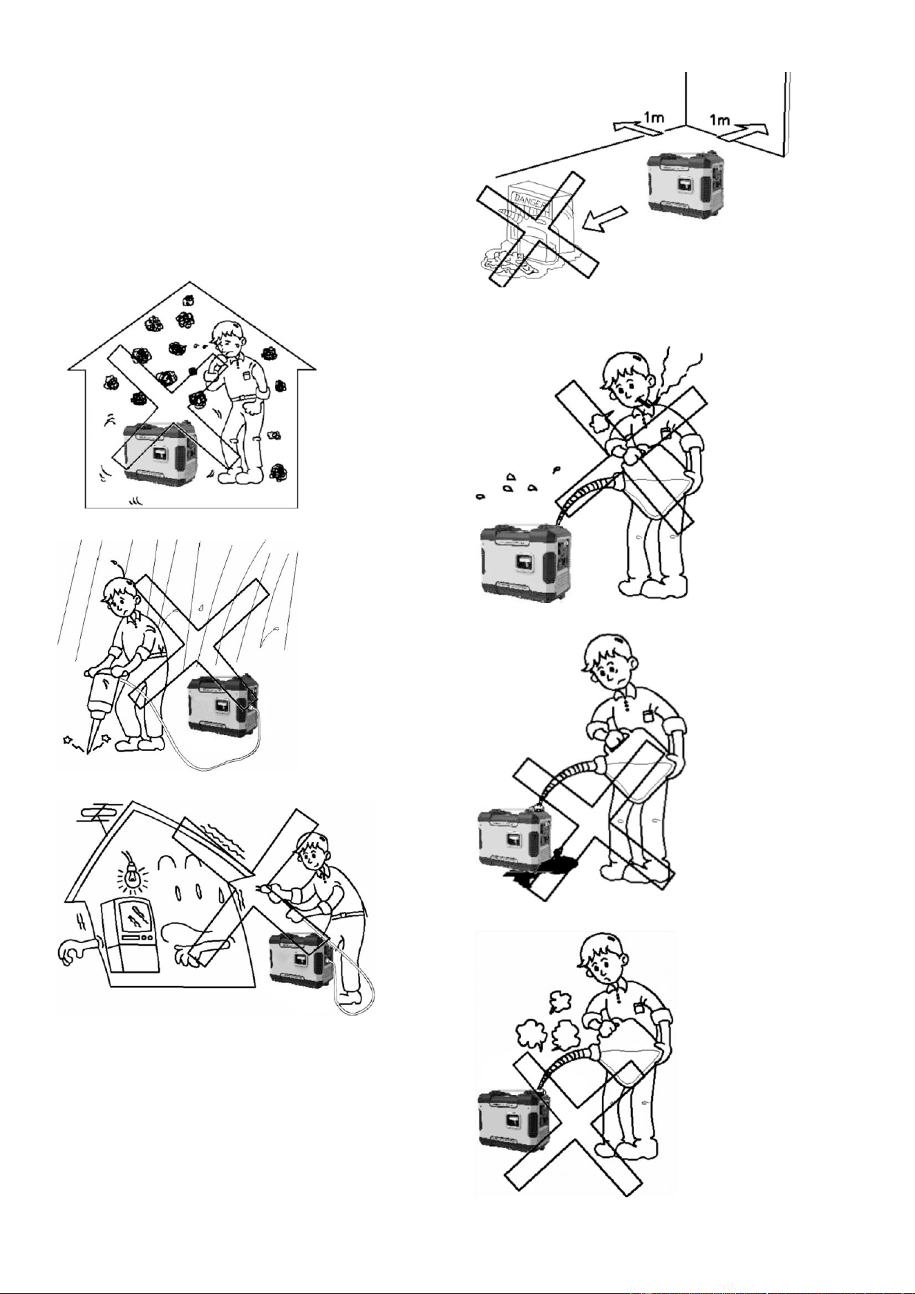
Never use it indoor. Fig.1
Never use it in a wet condition. Fig.2
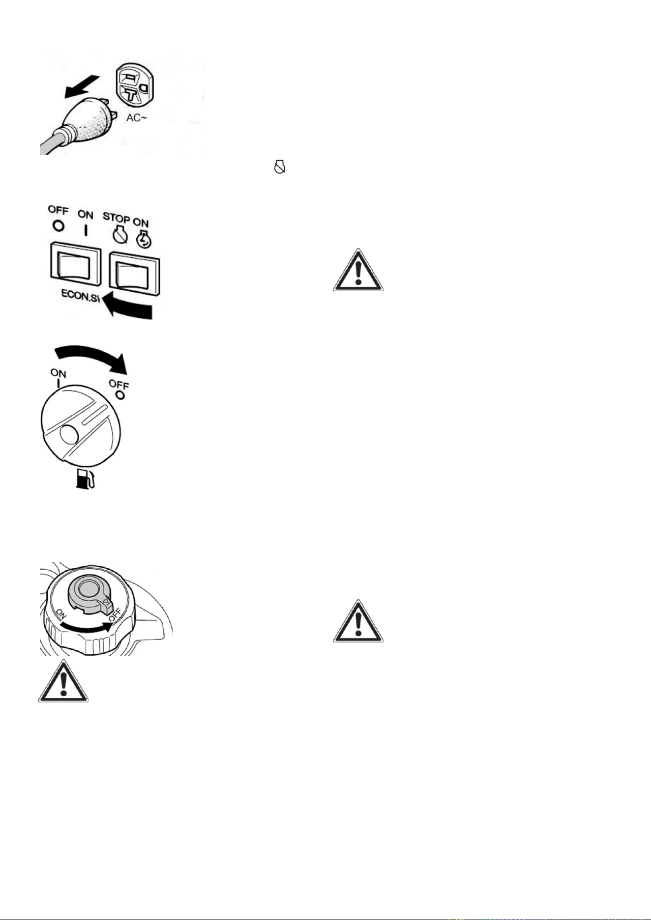
Never directly connect it to a
house power system. Fig.3
Keep it at least 1m away from
inflammable. Fig.4
Never smoke when fueling. Fig.5
Don’t spill when fueling. Fig.6
Stop engine when fueling. Fig.7
6
CONNECTION TO A HOUSE
POWER SUPPLY
WARNING: If this generator is
used as a supply for a building’s wiring
system as a standby, the generator must
be installed by a qualified electrician and
connected to a transfer switch as a
separately derived system in accordance
with the National Electrical Code, NFPA
70. The generator shall be connected to
a transfer switch that switches all
conductors excluding the equipment
grounding conductor. The frame of the
generator shall be connected to an
approved grounding electrode. Any
improper connection may cause damage
to the generator, or cause a fire.
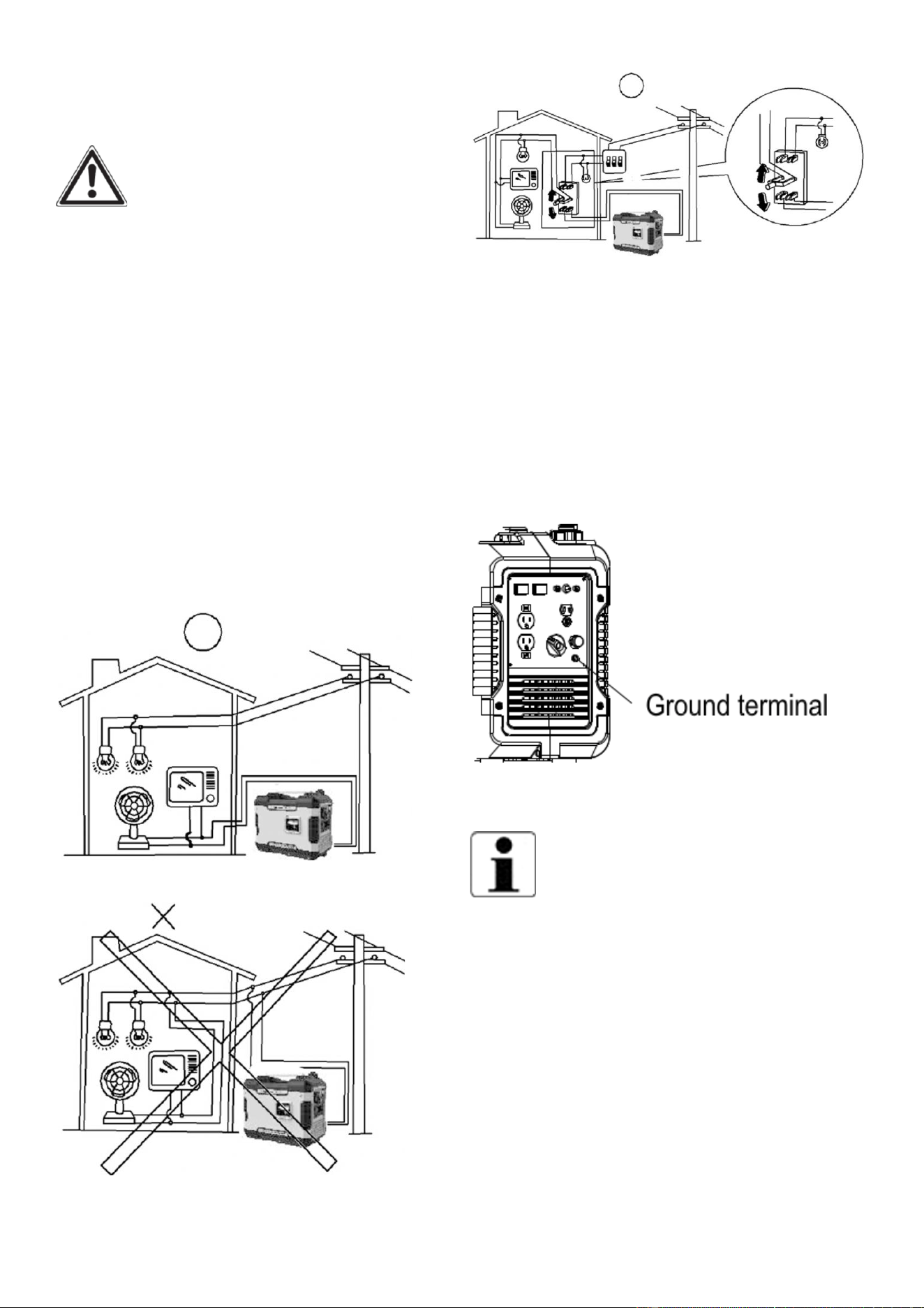
Fig.8
Fig.9
Fig.10
GENERATOR GROUND
CIRCUIT
In order to prevent electric shock due to
shoddy electrical appliances or wrong
use of electricity, the generator must be
grounded with a good-quality insulated
Conductor.
Fig.11
CAUTION:
Make sure the control panel, louver and
the inverter bottom side cooling well and
without chips, mud and water come in. it
may damage the engine, inverter or
alternator if the cooling vent blocked.
Do not mix the generator with other stuff
If moving, storing or running the unit.
It may cause the generator damage or
property safety issue when the generator
in leakage.

7
PRODUCT SPECIFICATIONS
Model
Generator
Type
Inverter
Rated Frequency (Hz) 60
Rated Voltage (V)
120
Rated Output Power (KW) 1.6
Max Output Power (KW)
2.0
Power Factor 1.0
Charging Voltage (DC)(V)
12
Charging Current (DC)(A) 8
Overload Protect (DC)
Non-fuse Protector
USB Port 5V, 1 A&2.1A
Phase
Single
Engine
Engine Type
Single cylinder, 4-stroke, forced air
cooling, OHV
Displacement (cc) 79.7
Fuel Type Unleaded Gasoline
Fuel Tank Capacity 1 US gallon (4 liters)
Fuel Consump�on (g/KW·) ≤450
Con�nue Running Time
(at rated power)
4 hours
Oil Capacity
0.37 quarts (0.35 liters)
Spark Plug Model No. E6TC/E6RTC
Star�ng Mode Recoil Starter
Generator
Set
Length×Width×Height
480×285×390 (mm)
Net weight 47.4 lbs
R2000i
8
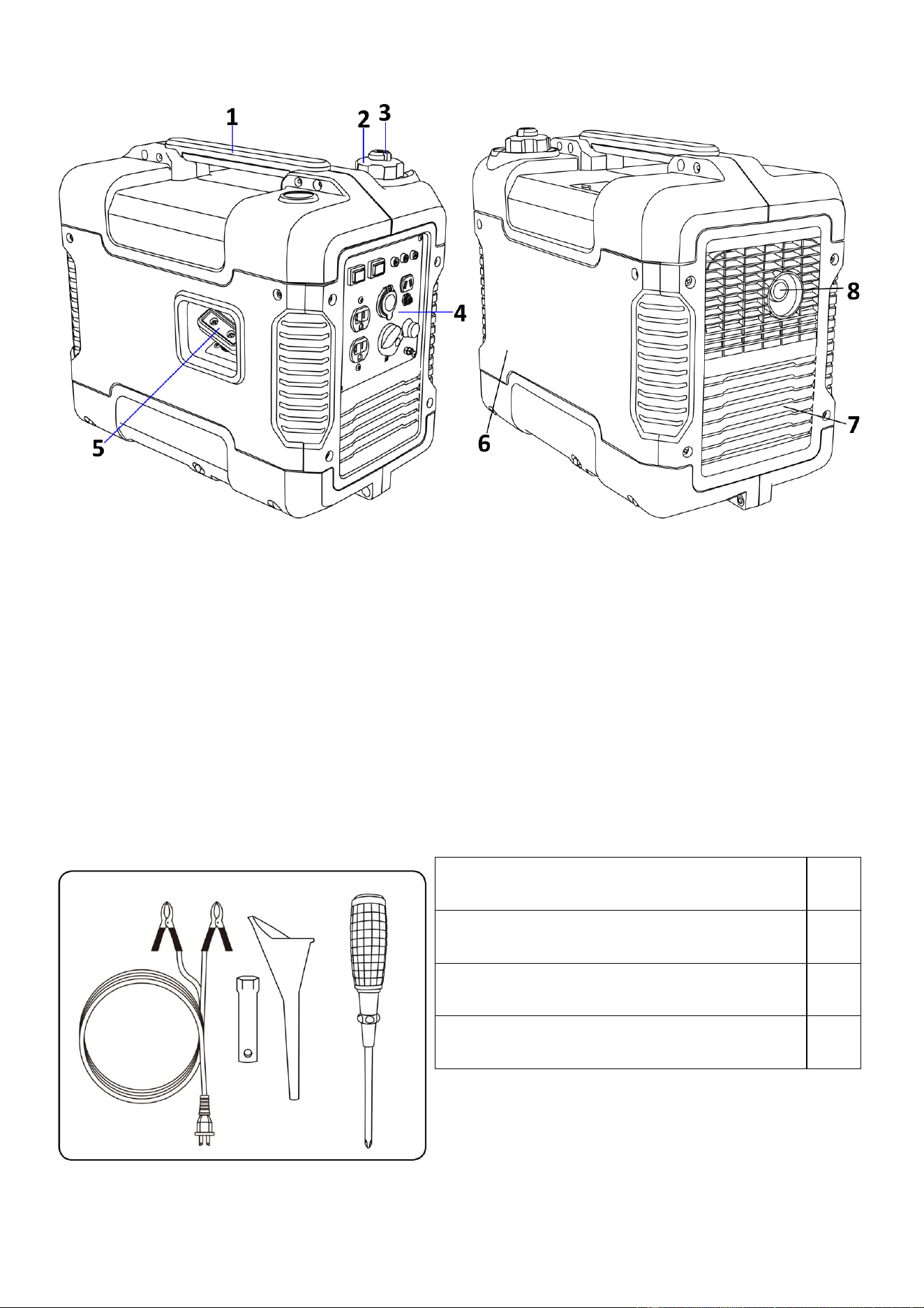
KNOW YOUR INVERTER GENERATOR
Fig.12
①
Carrying handle
⑤
Recoil starter
②
Fuel tank cap
⑥
Oil filler cap
③
Fuel tank cap air vent knob
⑦
Louver
④
Control panel
⑧
Muffler
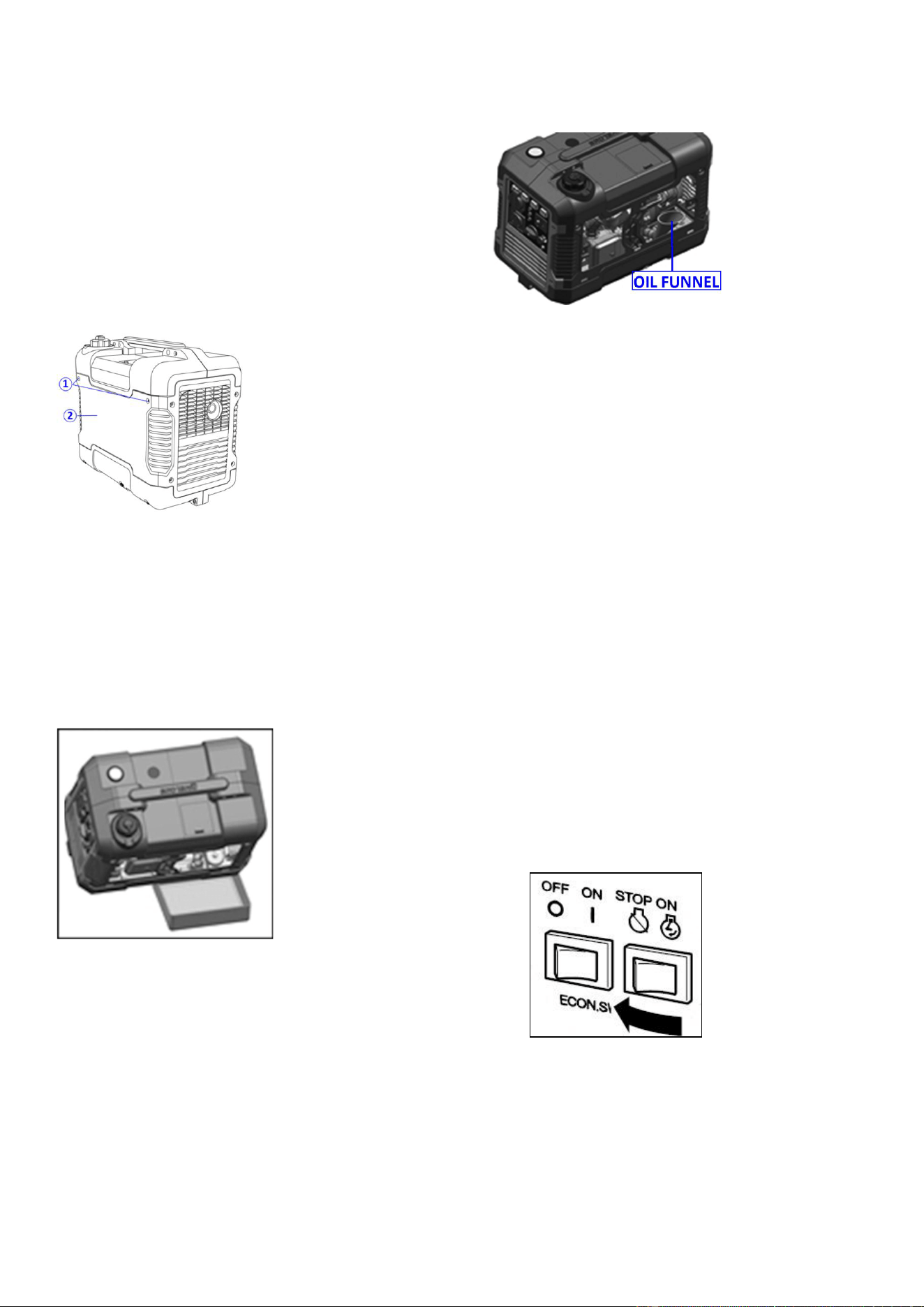
ACCESSORIES
12V DC Battery charging cable
1
Spark plug socket
1
Oil funnel
1
Screw driver
1
Fig.13
9
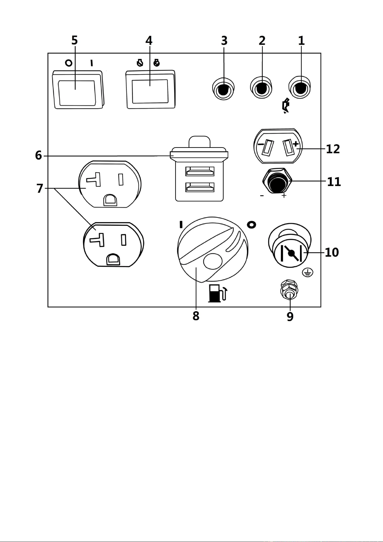
Control Panel
Fig.14
1 Oil warning light 7 AC receptacle
2 AC pilot light 8 Fuel cock knob
3 Overload indicator light 9 Ground (earth)
terminal
4 Engine switch (Red) 10 Choke knob
5 Economy control switch
(Black)
11 DC protector
6 USB Port (1A/2.1A) 12 DC receptacle
10
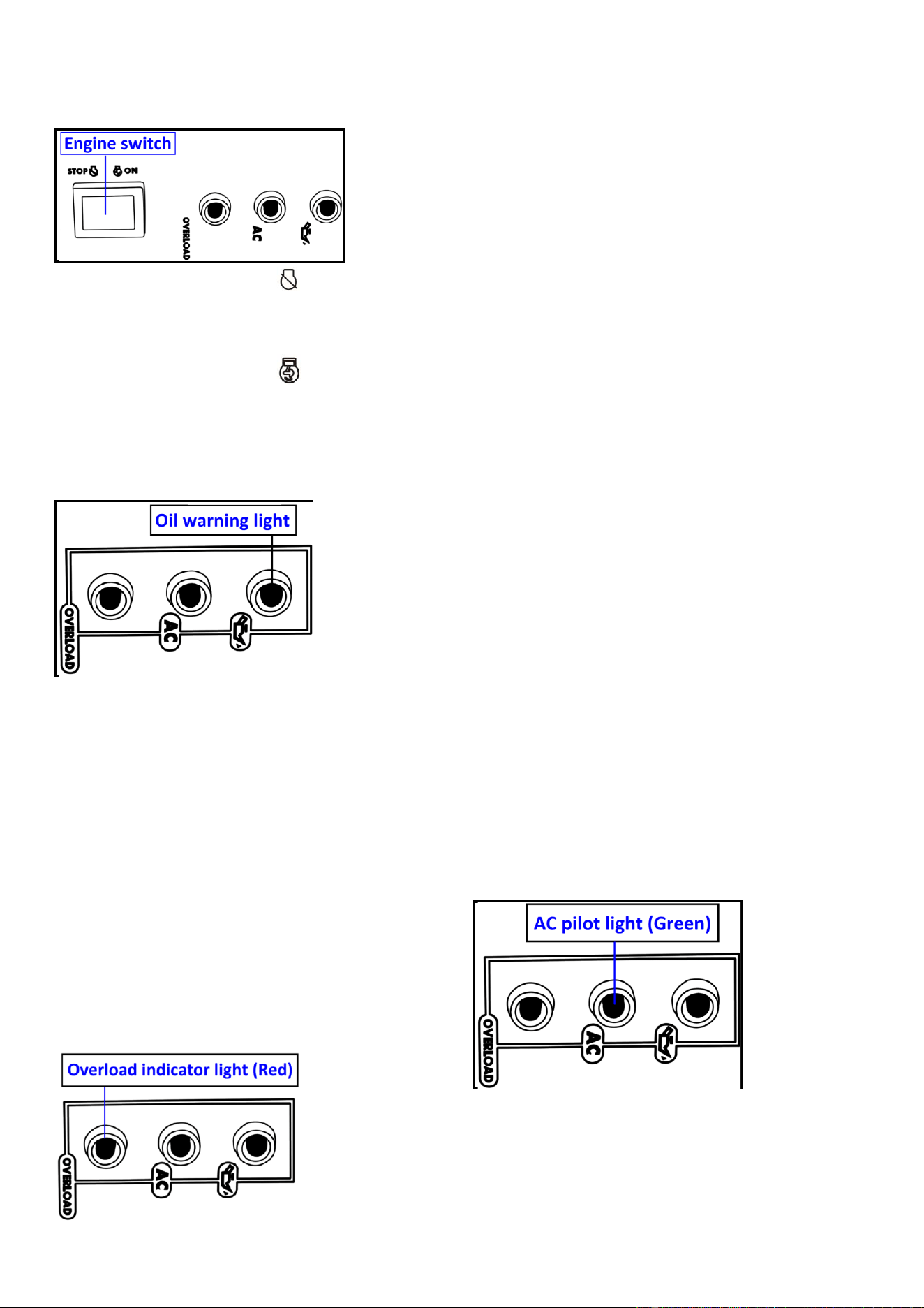
CONTROL FUNCTION
Engine switch (Red)
Fig.15
1. Engine switch (Red) “STOP”;
Ignition circuit is switched off. The
engine will not run.
2. Engine switch (Red) “ON”;
Ignition circuit is switched on. The engine
can be running.
Oil warning light (yellow)
Fig.16
When the oil level falls below the lower
level, the oil warning light (yellow) comes
on and then the engine stops
automatically. Unless you refill with oil,
the engine will not start again.
NOTE: If the engine stalls or does not
start, turn the engine switch to “ON” and
then pull the recoil starter.
If the oil warning light (yellow) flickers for
a few seconds, the engine oil is
insufficient . Add oil and restart.
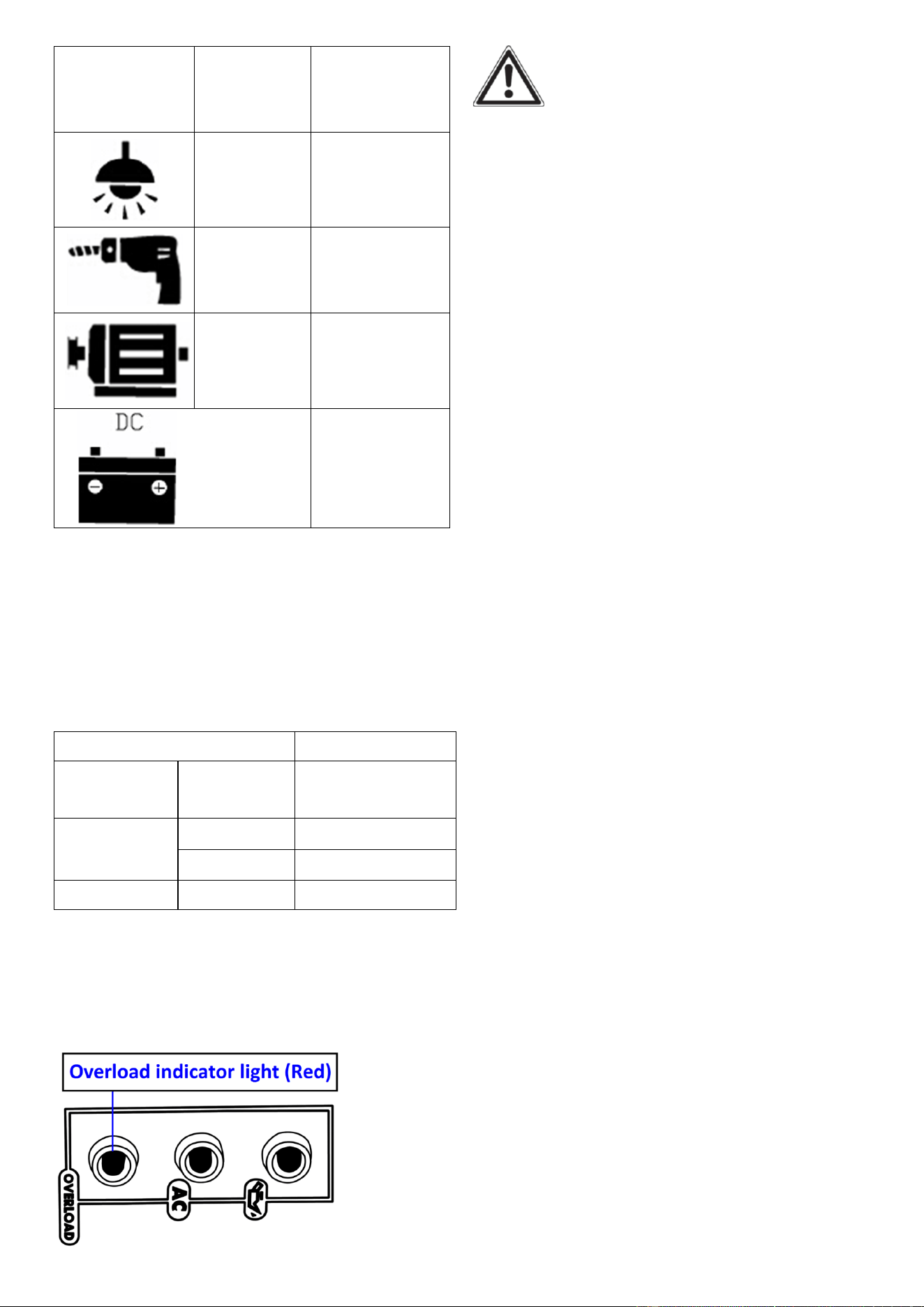
Overload indicator light (Red)
Fig.17
The overload indicator light (Red) comes
on when an overload of a connected
electrical device is detected, the inverter
control unit overheats, or the AC output
voltage rises. Then, the AC protector will
trip, stopping power generation in order
to protect the generator and any
connected electric devices. The AC pilot
light (Green) will go off and the overload
indicator light (Red) will stay on, but the
engine will not stop running.
When the overload indicator light (Red)
comes on and power generation stops,
proceed as follows:
1. Turn off any connected electric devices
and stop the engine.
2. Reduce the total wattage of connected
electric devices within the rated output.
3. Check for blockages in the cooling air
inlet and around the control unit.
If any blockages are found, remove.
4. After checking, restart the engine.
NOTE: The overload indicator light (Red)
may come on for a few seconds at first
when using electric devices that require a
large starting current, such as a
compressor or a submergible pump.
However, this is not a malfunction.
AC pilot light (Green)
Fig.18
The AC pilot light (Green) comes on when
the engine starts and produces power.
DC protector
The DC protector (11) turns to “OFF”
automatically when electric device being
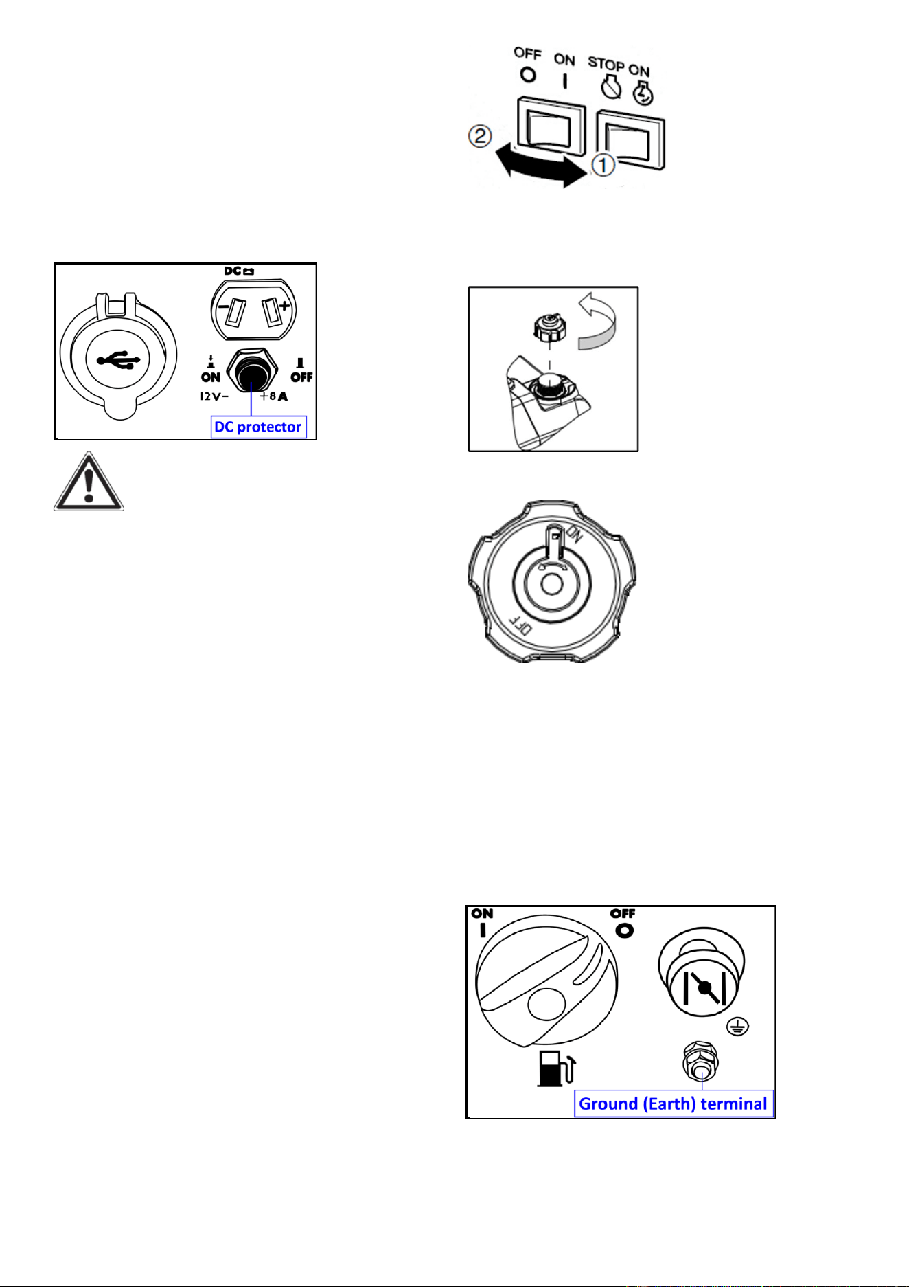
11
connected to the generator is operating
and current above the rated flows. To use
this equipment again, turn on DC
protector by pressing its button to “ON”.
1. “ON”: Direct current is output.
2. “OFF”:Direct current is not output.
Fig.19
CAUTION:
Reduce the load of the connected electric
device below the specified rated output of
the generator if the DC protector turns off.
If the DC protector turns off again, stop
using the device immediately and consult
customer service center.
Economy control switch (ECS)
1. “ON”
When the ESC (5) switch(Black) is turned
to “ON”, the economy control unit
controls the engine speed according to
the connected load. The results are better
fuel consumption and less noise.
2. “OFF”
When the ECS switch (Black) is turned
to“OFF”, the engine runs at the rated
speed 5000r/min regardless of whether is
a load connected or not.
NOTE:
The ECS switch (Black) must be turned
to“OFF” when using electric devices that
require a large starting current, such as a
compressor of a submergible pump.
Fig.20
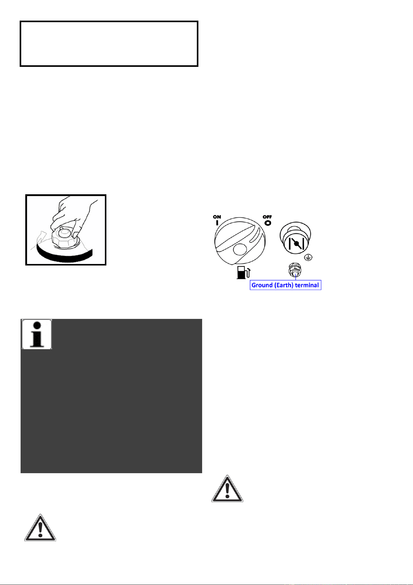
Fuel tank cap
Remove the fuel tank cap by turning it
counterclockwise.
Fig.21
Fuel tank cap air vent knob
Fig.22
The fuel tank cap is provided with an air
vent knob to stop fuel flow. The air vent
knob must be turned to “ON”. This will
allow fuel to flow to the carburetor and
the engine to run. When the engine is not
in use, turn the air vent knob to “OFF” to
stop fuel flow.
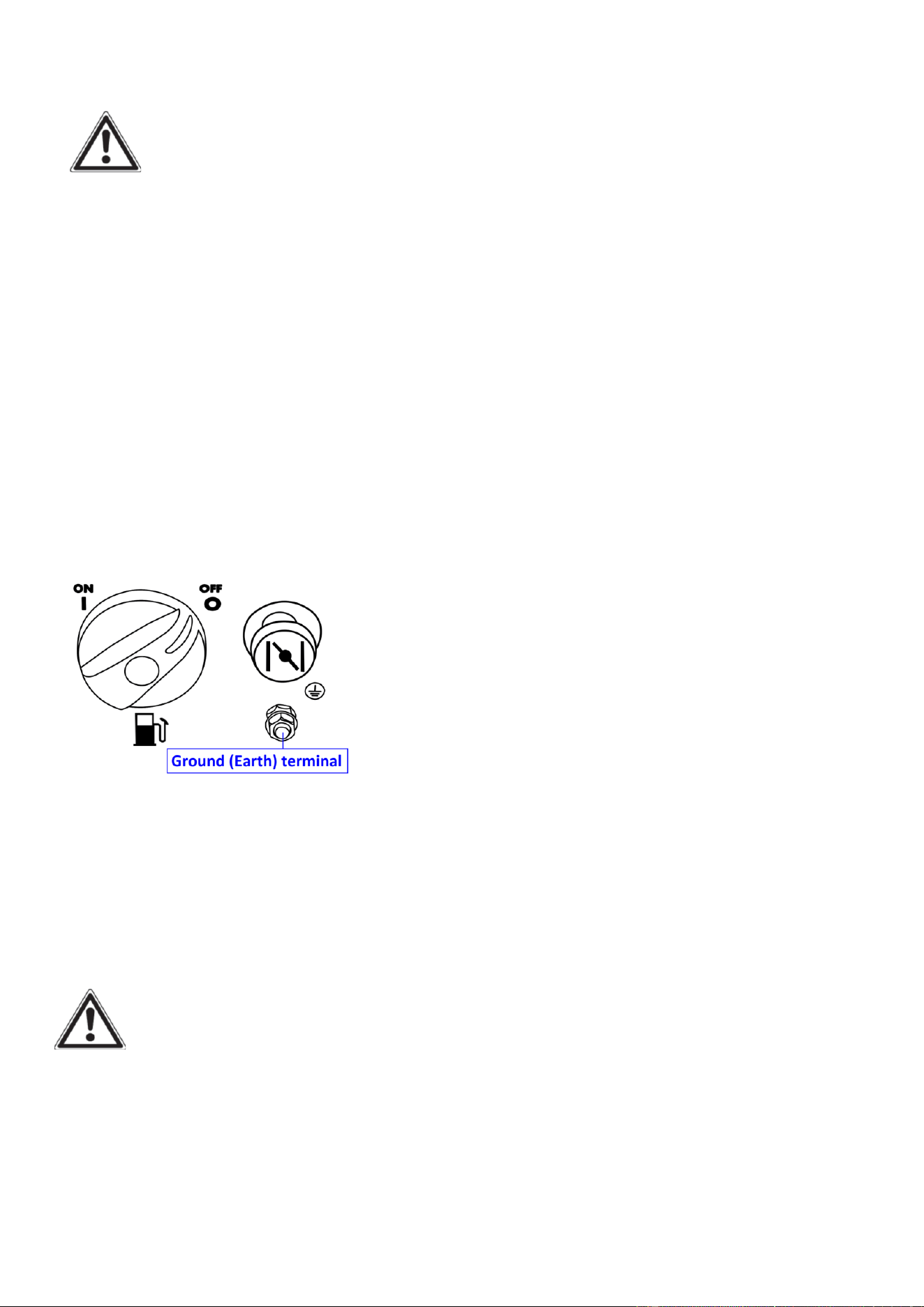
Ground (Earth) terminal
Fig.23
Ground (Earth) terminal connects the
earth line for prevention of electric shock.
When the electric device is earthed,
always the generator must be earthed.
12
GENERATOR
PREPARATION
USING THE GENERATOR FOR
THE FIRST TIME
The following section describes
steps necessary to prepare the generator
for use. If after reading this section, you
are unsure about how to perform any of
the steps please call for customer service.
Failure to perform these steps properly
can damage the generator or shorten its
life.
Step 1- ADD OIL
The generator is shipped without oil. User
must add the proper amount of oil before
operating the generator for the first time.
The oil capacity of the engine crankcase is
0.37 quarts (0.35 liters). For general use
(above 40° F), we recommend 30W,
4-stroke engine oil.
Do not start the engine till fill with the
sufficient engine oil.
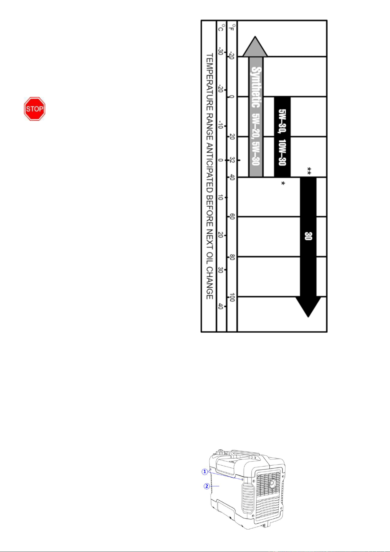
Engine Oil Recommendations
Select good quality detergent oil bearing
the American Petroleum Institute (API)
service classifications SJ, SL, or SM.
(Synthetic oils may be used.) Use the ASE
viscosity grade of oil from the following
chart (Fig.24) that matches the starting
temperature anticipated before the next
oil changes.
Fig.24
Engine Oil Replacemendations
To add oil, follow these steps:
1. Make sure the generator is on a level
surface. Tilting the generator to assist in
filling will cause oil to flow into engine
areas and will cause damage. Keep
generator level!
2. Remove the screws ①, and then
remove the access panel ②.
Fig.25
13
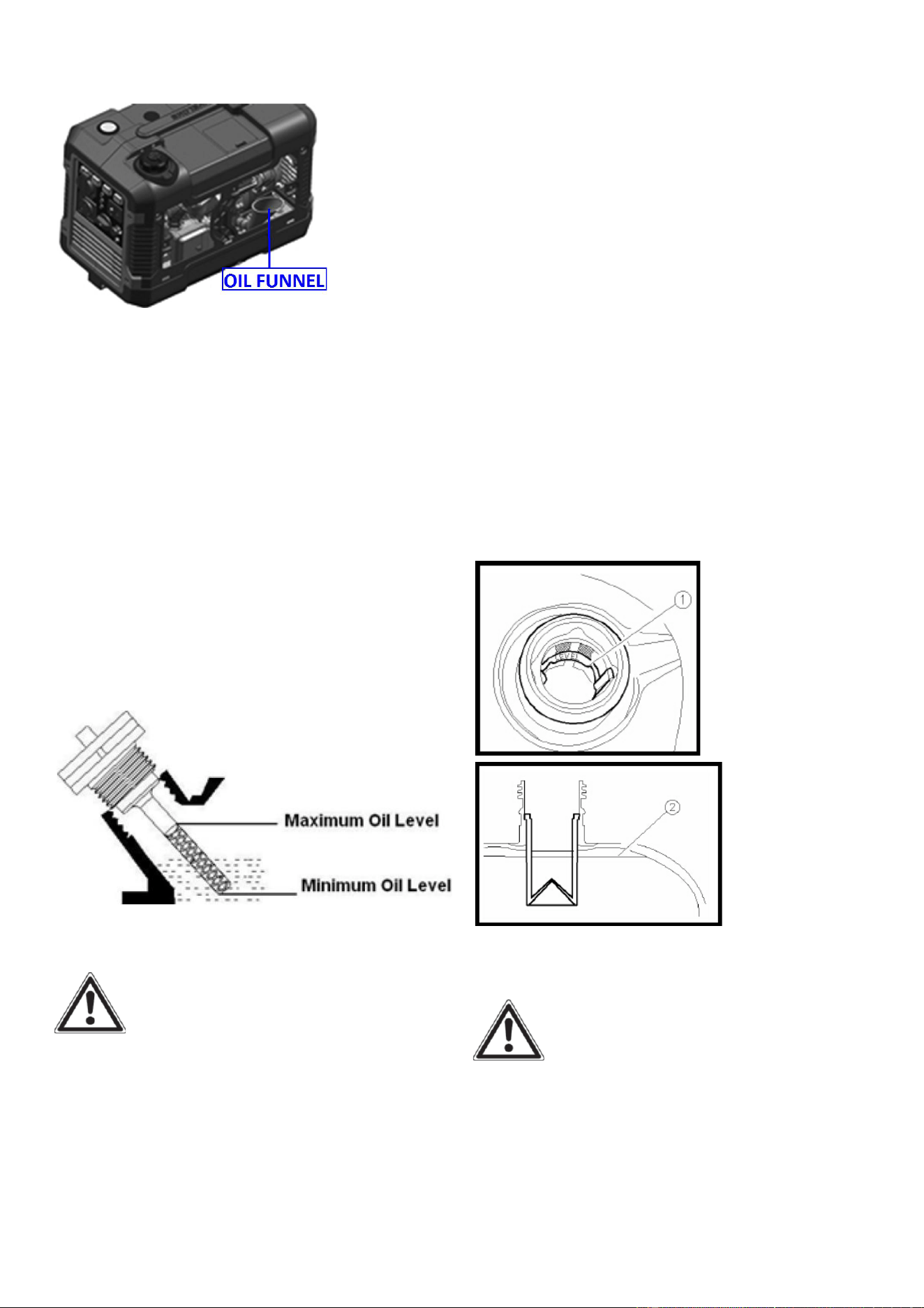
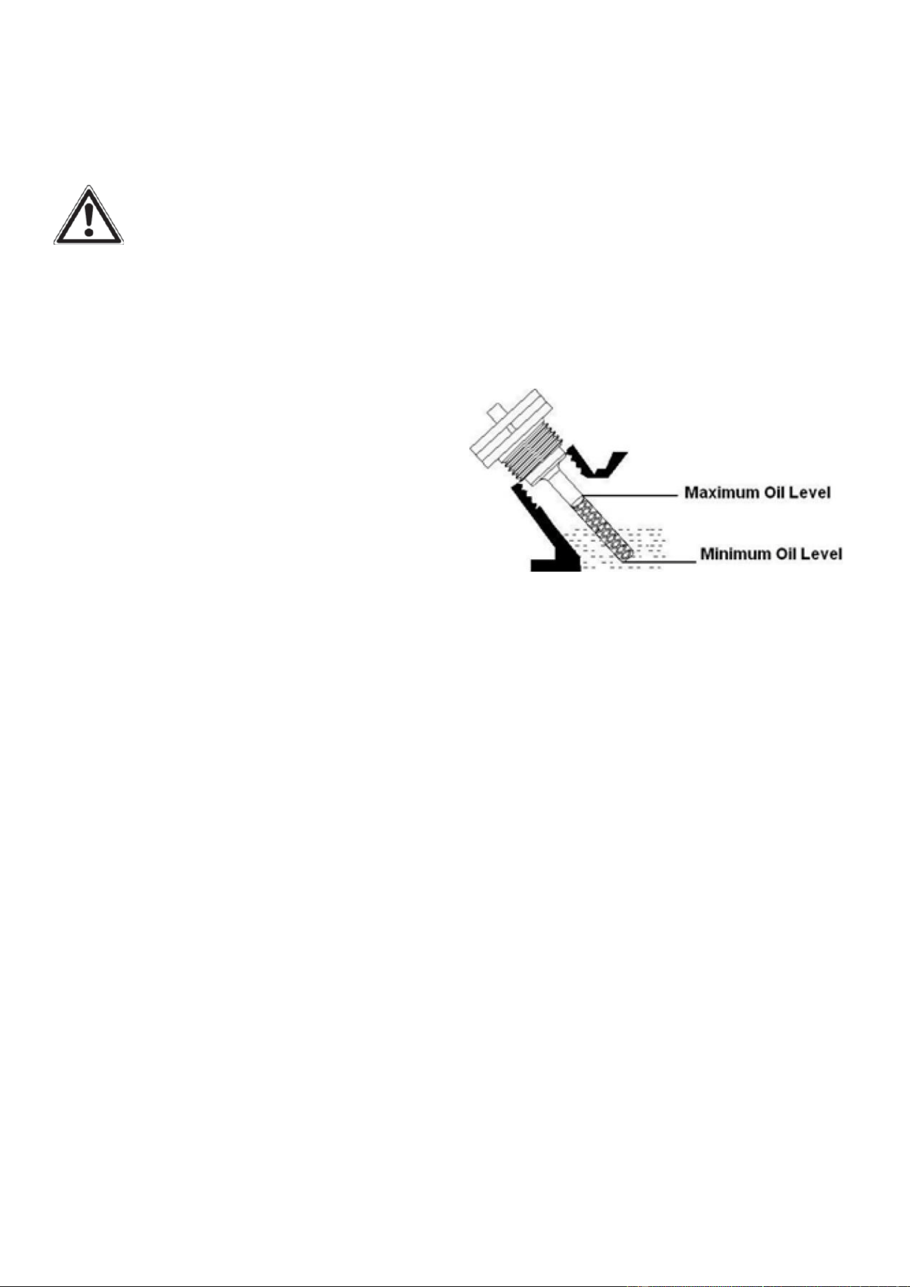
3. Remove the dipstick from the engine.
Insert the oil funnel. (Fig.26)
Fig.26
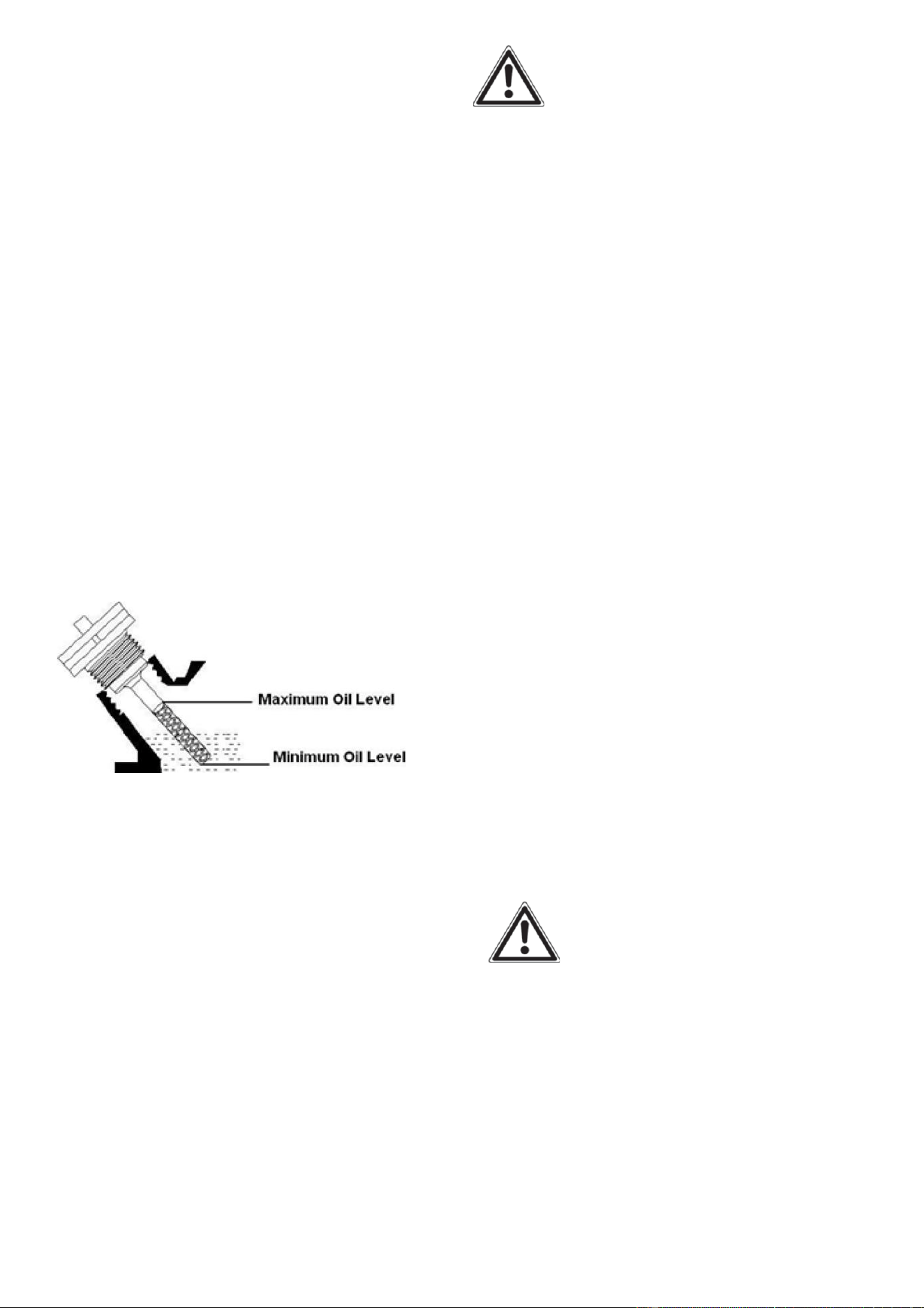
4. Add oil slowly to bring level to full. (Fig.
27).
5.To check the oil level: wipe the dipstick
with a clean rag. Insert the dipstick into
the oil fill opening without screwing in.
Remove the dipstick to check the oil mark.
6. Slowly add more oil and repeat step 4
until the oil mark reaches to the top of the
dipstick (Fig.27). Do not over fill the
crankcase. The generator is equipped with
a low oil sensor and will not start if the
amount of oil is in sufficient.
7. Check for oil leaks. Tighten dipstick
firmly before closing the access panel.
Fig.27 Oil Fill Opening, Dipstick and Oil Level
Step 2-ADD GASOLINE
DANGER:
This generator may emit highly
flammable and explosive gasoline
vapors, which can cause severe burns
or even death if ignited. A nearby open
flame can lead to explosion even if not
directly in contact with gasoline.
Use fresh (within 30 days from purchase),
lead-free gasoline with a minimum of 87
octane rating. Do not mix oil with
gasoline.
To add gasoline, follow these steps:
1. Make sure the generator is on a level
surface.
2. Unscrew fuel cap and set aside.
NOTE: The fuel cap may be tight and
hard to unscrew.
3. Slowly add unleaded gasoline to the
fuel tank up to the red level.① Red line
② Fuel level.
Be careful not to overfill. The capacity of
the fuel tank is 1 US gallon.NOTE: Do
not fill the fuel tank to the very top.
Gasoline will expand and spill over during
use when the fuel warms up even with the
fuel cap in place.
Fig.28
Fig.29
4. Reinstall fuel cap and wipe clean any
spilled gasoline with a dry cloth.
IMPORTANT:
• Use only unleaded gasoline. The use of
leaded gasoline will cause severe damage
to internal engine parts.
14
Recommended fuel: Unleaded gasoline
Fuel tank capacity: Total: 4.0L(1.06 US
gal, 0.88 lmp gal)
• Never use an oil/gasoline mixture.
• Never use old gasoline.
• Avoid getting dirt or water into the fuel
tank.
• Gasoline can age in the tank and make
starting difficult. Never store generator
for extended periods of time with fuel in
the tank.
• After fill the fuel, make sure the fuel
tank cap is tightened securely.
Fig.30
• Immediately wipe off spilled fuel with a
clean, dry, soft cloth, since fuel may
deteriorate painted surfaces or plastic
parts.
NOTE: Fuel deteriorates over
time. It may be DIFFICULT to
start the engine if you use fuel
which has been kept for more
than 30 days. Towards the end of the
season, it is advisable to put only as
much fuel in the tank as you need for
each use, since it should be completely
used up before storing the product.
Empty remaining fuel from the tank and
the CARBURETTOR when storing the
product for over 30 days.
Step 3-GROUND THE
GENERATOR
WARNING: Failure to properly
ground the generator can result in
electrocution.
Ground the generator by tightening the
grounding nut on the front control panel
against a grounding wire. A generally
acceptable grounding wire is a No. 12
AWG (American Wire Gauge) stranded
copper wire. This grounding wire should
be connected at the other end to a copper,
brass, or steel-grounding rod that is driven
into the earth. Wire and grounding rods
are not included in generator contents.
Grounding codes can vary by location.
Contact a local electrician to check the
area codes.
Fig.31
NOTE: After completing the above
preparation, the generator is ready to be
started.
STARTING THE
GENERATOR
Before starting the generator, make sure
you have read and performed the steps in
the “Generator Preperation” section of
this manual. If you are unsure about how
to perform any of the steps in this manual
please call customer service center.
DANGER: CARBON
MONOXIDE.
Using a generator indoors CAN KILL YOU
IN MINUTES.
15
Generator exhaust contains carbon
monoxide (CO). This is a poison gas you
cannot see or smell. If you can smell the
generator exhaust, you are breathing CO.
Even if you cannot smell the exhaust, you
may be breathing CO.
NEVER use a generator inside homes,
garages, crawlspaces, or other partly
enclosed areas. Deadly levels of carbon
monoxide can build up in these areas.
Using a fan or opening windows and doors
does NOT supply enough fresh air.
ONLY use a generator outside and far
away from windows, doors, and vents.
These openings can pull in generator
exhaust. Even if you use a generator
correctly, CO may leak into the home.
ALWAYS use a battery- powered or
battery-backup CO alarm in the home.
If you start to feel sick, dizzy, or weak
after the generator has been running,
move to fresh air RIGHT AWAY. See a
doctor. You may have carbon monoxide
poisoning.
WARNING: This generator
produces powerful voltage, which can
result in electrocution.
ALWAYS ground the generator before
using it (see the “Ground the Generator”
portion of the “Generator Preperation”
section).
Generator should only be plugged into
electrical devices, either directly or with
an extension cord. NEVER connect to a
building electrical system without a
qualified electrician. Such connections
must comply with local electrical laws and
codes. Failure to comply can create a
back-feed, which may result in serious
injury or death to utility workers.
-Use a ground fault circuit interrupter
(GFCI) in highly conductive areas such as
metal decking or steel work. GFCIs are
available in-line with some extension
cords.
-Do not use in rainy or wet conditions.
-Do not touch bare wires or receptacles
(outlets).
-Do not allow children or non-qualified
persons to operate.
CAUTION:Disconnect all electrical
loads from the generator before
attempting to start.
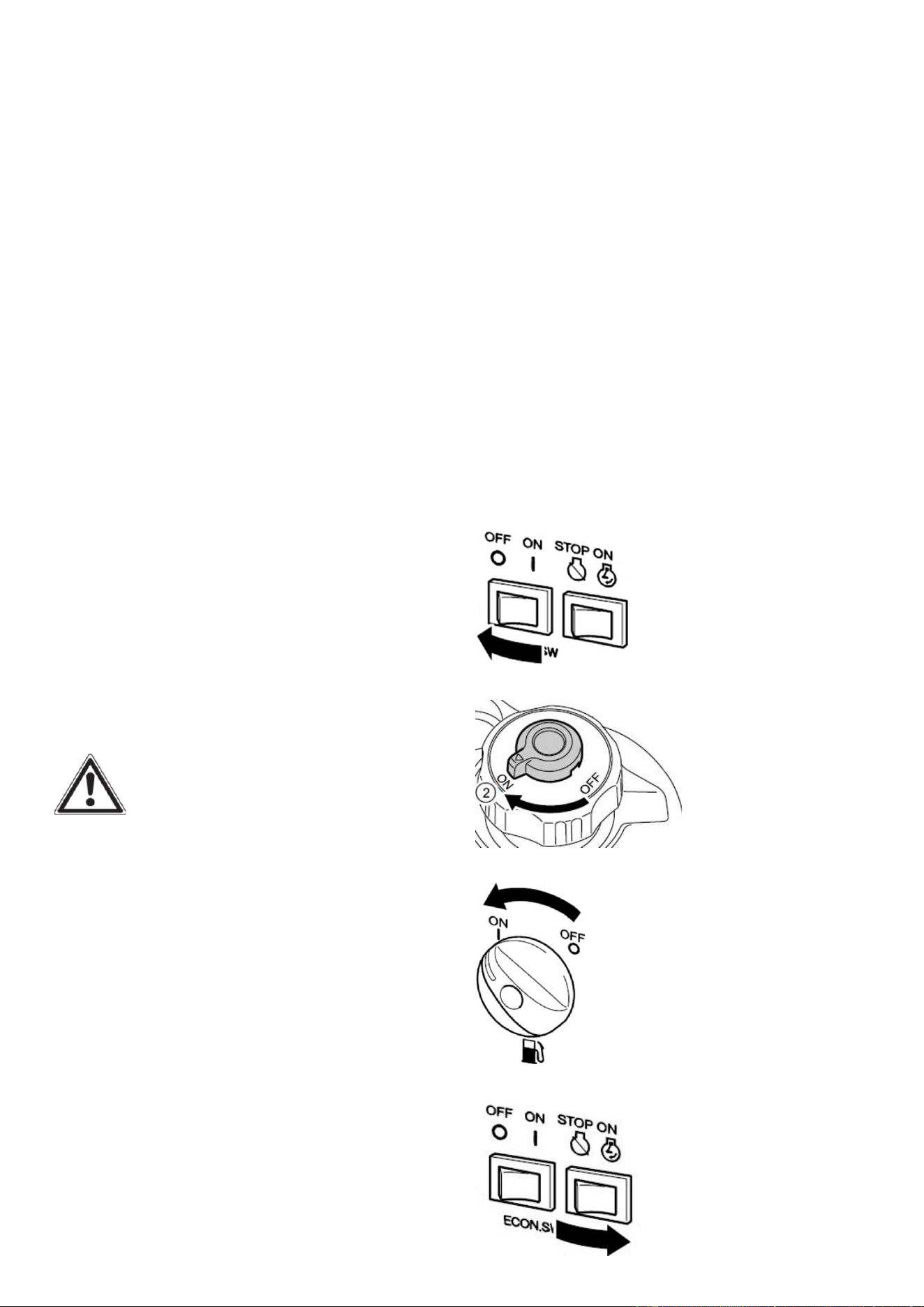
STARTING THE ENGINE
1. Turn the ECS switch(Black) to “OFF”.
Fig.32
2. Turn the air vent knob to “ON” .
Fig.33
3. Turn the fuel cock knob to “ON”.
Fig.34
4. Turn the engine switch (Red) to “ON”.
Fig.35
16
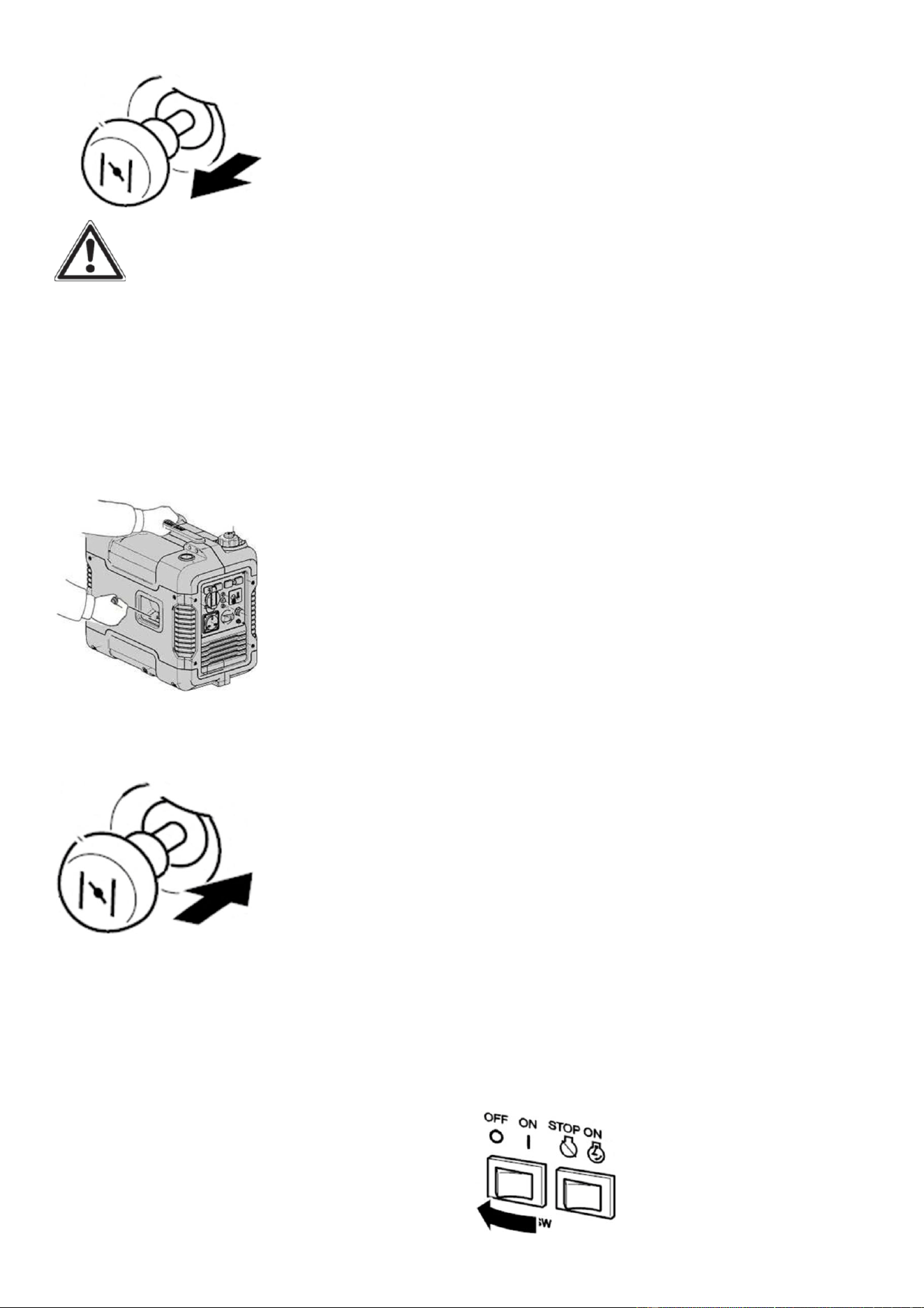
5. Pull the choke knob fully out.
Fig.36
WARNING: The choke is not
required to start a warm engine. Push the
choke knob fully in.
6. Pull slowly on the recoil starter until it is
engaged, then pull it briskly.
NOTE: Grasp the carrying handle firmly
to prevent the generator from falling over
when pulling the recoil starter.
Fig.37
7. After the engine starts, warm up the
engine until the engine does not stop.
Then press push the choke knob fully in.
Fig.38
NOTE: When starting the engine, with
the ESC “ON”, and there is no load on the
generator:
• In ambient temperature below
0℃(32℉), the engine will run at the rated
r/min (5000r/min) for 5 minutes to warm
up the engine.
• In ambient temperature below
5℃(41℉) , the engine will run at the
rated r/min (5000r/min) for 3 minutes to
warm up the engine.
• The ESC unit operates normally after the
above time period, while the ECS switch
(Black) is “ON”.
ECO-MODE IDLE CONTROL
SWITCH
This generator is equipped with an
Eco-Mode Idle Control Switch. Engaging
the switch will automatically adjust the
engine speed to match the load at hand.
When an electrical device comes on line,
the generator engine will automatically
speed up to supply the power needed and
will slow down as the need decreases. The
variable engine speed can reduce fuel
consumption and noise level. Keep this
switch engaged when the power load
requirement is less than 1000W. Do not
engage the Idle Control Switch when the
total load is more than 1000W. The
generator engine must run at full speed to
supply the required power for anything
over 1000W.
STOPPING THE
GENERATOR
To Stop The Generator
1. Turn off all electrical devices prior to
unplugging them from the generator.
NOTE: Unplugging running devices can
cause damage to the generator.
2. Turn the ECS switch (Black) to “OFF”.
Fig.39
17
2. Disconnect any electric devices.
Fig.40
3. Turn the engine switch (Red) to
“STOP” .
Fig.41
4. Turn the fuel cock knob to “OFF”.
Fig.42
5. Turn the fuel tank cap air vent knob to
“OFF” after the engine has completely
cooled down.
Fig.43
WARNING: Allow the generator
to cool for several minutes before
touching areas that become hot during
use.
CAUTION: Allowing gasoline to sit in
the fuel tank for long periods of time can
make it difficult to start the generator in
the future. Never store the generator for
extended periods of time with fuel in the
fuel tank. Drain off the gasoline in the
carburettor. Refer to “Generator Storage
“Section.
SUBSEQUENT
STARTING OF
THE GENERATOR
PRE-OPERATION CHECK
WARNING:
If any item in the Pre-operation check is
not working properly, have it inspected
and repaired before operating the
generator.
The condition of a generator is the
owner’s responsibility. Vital components
can start to deteriorate quickly and
unexpectedly, even if the generator
unused.
NOTE: Pre-operation checks should be
made each time the generator is used.
If this is not the first time using the
generator, the user should take the
following steps to prepare it for
operation.
IMPORTANT: At this point the
user should be familiar with the
procedures described in the section titled
“Using the Generator for the First Time.”
If the user has not yet read this section, go
back and read it now.
Step 1 - CHECK THE OIL
Oil consumption is normal during
generator use. The generator is equipped
with a low oil pressure shutoff to protect
it from damage. The oil level of the engine
18
should be checked before each use to
ensure that the engine crankcase contains
sufficient lubricant.
To check or add oil, follow these steps:
1. Place the generator on a level
surface.
2. Check oil level in engine: Open
access panel. Clean around oil fill hole.
Remove dipstick and wipe the dipstick
with a clean rag. Insert the dipstick into
the oil fill opening without screwing in.
Remove the dipstick to check the oil
mark. Add recommended oil if the oil
mark covers less than specified level.
3. Slowly add more oil and repeat step
2 until the oil mark reaches to the top
of dipstick (Fig.44). Do not over fill the
crankcase.
Fig.44 Oil Fill Opening, Dipstick and Oil Level
4. Tighten dipstick firmly then put back
access panel before starting the engine.
5. Check generator for oil leakage.
The point where abnormality was
recognized by use.
6. Check operation. If necessary, add
recommended oil to specified level.
Step 2 - CHECK THE FUEL
LEVEL
Before starting the generator, check to
see that there is sufficient gasoline in
the fuel tank. Add additional gasoline
as necessary but leave sufficient room
in tank for expansion.
WARNING: This generator
may emit highly flammable and
explosive gasoline vapors, which can
cause severe bums or even death if
ignited. A nearby open flame can lead
to explosion even if not directly in
contact with fuel.
Do not operate near open flame.
Do not smoke near generator.
Always operate on a firm, level
surface.
Always turn generator off before
refueling. Allow generator to cool for
at least 2 minutes before removing
fuel cap. Loosen cap slowly to relieve
pressure in tank.
Do not overfill fuel tank. Gasoline
may expand during operation. Do not
fill to the top of the tank. Allow for
expansion.
Always check for spilled fuel before
operating. Clean up any spilled fuel
before starting.
Empty fuel tank before storing or
transporting the generator.
Before transporting, turn fuel
the air
vent knob to OFF position.
IMPORTANT:
Use only UNLEADED gasoline.
Do not use old gasoline.
Never use an oil/gasoline mixture.
Avoid getting dirt or water into the
fuel tank.
19
Step 3 - GROUND THE
GENERATOR
WARNING: Failure to
properly ground the generator can
result in electrocution.
Ground the generator by tightening
the grounding nut on the front control
panel against a grounding wire. A
generally acceptable grounding wire is
a No. 12 AWG (American Wire Gauge)
stranded copper wire. This grounding
wire should be connected at the other
end to a copper, brass, or
steel-grounding rod that is driven into
the earth. Wire and grounding rod are
not included in generator contents.
Fig.45
Grounding codes can vary by location.
Contact a local electrician for area
codes.
USING THE
GENERATOR
WARNING: When this
generator is used on a building’s wiring
system, the generator must be installed
by a qualified electrician and connected
to a transfer switch as a separately
derived system in accordance with the
National Electrical Code, NFPA 70. The
generator shall be connected to a
transfer switch that switches all
conductors other than the equipment
grounding conductor. The frame of the
generator shall be connected to an
approved grounding electrode.
For power outages, permanently
installed stationary generators are
better suited for providing backup
power to the home. Even a properly
connected portable generator can
become overloaded. This may result in
overheating or stressing the machine’s
components, possibly leading to a
generator failure.
Before connecting electrical devices,
allow the generator to run for a few
minutes to stabilize the speed and
voltage output.
CAUTION: Become familiar with the
markings on the panel before
connecting electrical devices.
Connect electrical devices running on
AC current according to their wattage
requirements. The chart in Fig 46
shows the rated and surge wattage of
the generator.
The rated (running) wattage is the
wattage the generator can produce
on a continuous basis.
The surge wattage is the maximum
amount of power the generator can
produce for an extremely short period
of time (seconds). Many electrical
devices such as refrigerators require
short bursts of extra power in
addition to the rated wattage listed
by the device to start their motors.

20
The surge wa�age ability of the
generator covers this extra power
requirement.
Item
Rated
(Running)
Wa�age
Surge
Wa�age
A2000i
1600 2000
Fig.46 - Generator Wa�age
The total running wa�age requirement
of the electrical devices connected to
the generator should not exceed the
rated wa�age of the generator itself.
To calculate the total wa�age
requirement of the electrical devices
you plan to connect, find the rated (or
running) wa�age of each device. This
number should be listed somewhere on
the device or in its instruc�on manual.
If this wa�age cannot be found,
calculate it by mul�plying the Voltage
requirement by the Amperage drawn:
Wa�s = Volts x A mperes
When the rated wa�age requirement
of each electrical device has been
determined, add these numbers to find
the total rated wa�age needed. If this
number exceeds the rated wa�age of
the generator, DO NOT connect all
these devices. Select a combina�on of
electrical devices, which have a total
rated wa�age lower than or equal to
the rated wa�age of the generator.
CAUTION: The generator can run at
its surge wa�age capacity for only a
short �me. Connect electrical devices
requiring a rated (running) wa�age
equal to or less than the rated wa�age
of the generator. Never connect
devices requiring a rated wa�age equal
to the surge wa�age of the generator.
This can trip the circuit protectors
(circuit breakers).
NOTE: Check the wa�age on the
electrical device . Once the electrical
devices that will be powered by the
generator have been determined,
connect these devices according to the
following procedure:
1. Plug in each electrical device, making
sure that the device is turned off.
2. Check the overload light and power
indicator light. If the overload light is on,
unplug the electronics, then restart the
generator before plugging the load
back in. If the reset bu�on does not
reset, wait several minutes and try
again. If the power light s�ll does not
come on, call the customer service
number for further instruc�ons.
CAUTION: Do not connect 50Hz
loads to the generator.
SOME NOTES ABOUT POWER CORDS
Long or thin cords can drain the power
provided to an electrical device by the
generator. When using such cords,
allow for a slightly higher rated wa�age
requirement by the electrical device.
See Fig.47 for recommended cords
based on the power requirement of the
electrical device.
Device
Requir
ement
s
Amps
2.5
5
7.5
10
15
Wa�s
(120V)
300
600
900
1200
1800
Max.
Cord
Length
(�) by
#8
wire
NR
NR
NR
NR
NR
#10
wire
NR
NR
350
250
150

21
Wire
Gauge
#12
wire
NR
300
200
150
100
#14
wire
375
200
125
100
65
#16
wire
250
125
100
50
NR
Fig.47
*NR = Not Recommended
- Maximum Extension Cord Lengths by
Power Requirement.
If an overload occurs, shut down the
generator. Unplug all electrical devices
and wait five minutes. Then, start the
unit back up again to get power back.
WARNING:
• Never operate the engine in a closed
area or it may cause unconsciousness
and death within a short time. Operate
the engine in a well ventilated area.
• Before starting the engine, do not
connect any electric devices.
CAUTION:
• The generator has been shipped without
engine oil. Do not start the engine till fill
with the sufficient engine oil.
NOTE: Do not tilt the generator when
adding engine oil. This could result in
over filling and damage to the engine.
NOTE:
The generator can be used with the rated
output load at standard atmospheric
conditions.
“Standard atmospheric conditions”
Ambient temperature 25℃
Barometric pressure 100kPa
Relative humidity 30%
The output of the generator varies due to
change temperature, altitude (lower air
pressure at higher altitude) and humidity.
The output of the generator is reduced
when the temperature, the humidity and
the altitude are higher than standard
atmospheric conditions.
Additionally, the load must be reduced
when using in a confined areas, as
generator cooling is affected.
ALTERNATING CURRENT (AC)
CONNECTION
WARNING
Be sure any electric devices are turned off
before plugging them in.
CAUTION
• Be sure all electric devices including the
lines and plug connections are in good
condition before connection to the
generator.
• Be sure the total load is within
generator rated output.
• Be sure the receptacle load current is
within receptacle rated current.
NOTE: Make sure to ground (Earth) the
generator. When the electric device is
earthed, always the generator must be
earthed.
1. Start the engine.
2. Turn the ECS switch (Black) to “ON”.
3. Plug in to AC receptacle.
4. Make sure the AC pilot light (Green) is
on.
5. Turn on any electric devices.
NOTE: The ECS switch (Black) must be
turned to “OFF” to increase engine speed
to rated rpm. If the generator is
connected to multiple loads or electricity
consumers, please remember to first
connect the one with the highest starting
current, and last connect the one with the
lowest starting current.

22
BATTERY CHARGING
NOTE:
• The generator DC rated voltage is 12V.
• Start the engine first, and then connect
the generator to the battery for charging.
• Before starting to charge the battery,
make sure that the DC protector is turned
on.
1. Start the engine.
2. Connect the red battery charger lead to
the positive (+) battery terminal.
3. Connect the black battery charger lead
to the negative (-) battery terminal.
4. Turn the ECS switch (Black) “off” to
start battery charging.
CAUTION
• Be sure the ESC switch (Black) is turned
off while charging the battery.
• Be sure to connect the red battery
charger lead to the positive (+)battery
terminal , and connect the black lead to
the negative (-) battery terminal. Do not
reverse these positions.
• Connect the battery charger leads to the
battery terminals securely so that they
are not disconnected due to engine
vibration or other disturbances.
• Charge the battery in the correct
procedure by following instructions in
the owner’s manual for the battery.
• The DC protector turns off automatically
if current above the rated flows during
battery charging. To restart charging the
battery, turn the DC protector on by
pressing its button to “ON”. If the DC
protector turns off again, top charging
the battery immediately and consult our
company authorized dealer.
NOTE:
• Follow instructions in the owner’s
manual for the battery to determine
the end of battery charging.
• Measure the specific gravity of
electrolyte to determine if the battery is
fully charged. At full charge, the
electrolyte specific gravity is between
1.26 and 1.28.
• It is advisable to check the specific
gravity of the electrolyte at least once
every hour to prevent overcharging the
battery.
WARNING
Never smoke or make and break
connections at the battery while
charging. Sparks may ignite the battery
gas. Battery electrolyte is poisonous and
dangerous, causing severe burns, etc.
contains sulfuric (sulphuric) acid. Avoid
contact with skin, eyes or clothing.
Antidote:
EXTERNAL- Flush with water.
INTERNAL- Drink large quantities of water
or milk. Follow with milk of magnesia,
beaten egg or vegetable oil. Call physician
immediately. EYES: Flush with water for
15 minutes and get prompt medical
attention. Batteries produce explosive
gases. Keep sparks, flame, cigarettes, etc,
away. Ventilate when charging or using in
closed space. Always cover eyes when
working near batteries.
KEEP OUT OF REACH OF
CHILDREN.
APPLICATION RANGE
When using the generator, make sure the
total load is within rated output of a
generator. Otherwise, generator damage
may occur.
23
AC
Power
factor
Rated
output
power
1
≤1,600W
0.8-0.95
≤1,280W
0.4-0.75
(Efficiency
0.85)
≤544W
Rated
voltage 12V
Rated
current 8A
Fig.48
NOTE:
• Application wattage indicates when
each device is used by itself.
• The simultaneous usage of AC and DC
power is possible but total wattage should
not exceed the rated output. EX:
Generator rated output
1,600W
Frequency
Power
factor
AC
1.0
≤1,600W
0.8
≤1,280W
DC
--
96W(12V/8A)
Fig.49
The overload indicator light (Red) comes
on when total wattage exceeds the
application range. (See “CONTROL
FUNCTION” section for more details.)
Fig.50
CAUTION
• Do not overload. The total load of all
electrical appliances must not
exceed the supply range of the
generator . Overloading will damage the
generator.
• When supplying precision equipment,
electronic controllers, PC, Electronic
computers, microcomputer based
equipment or battery chargers, keep the
generator a sufficient distance away to
prevent electrical interference from the
engine. Also ensure that electrical noise
form the engine does not interfere with
any other electrical devices located near
the generator.
• If the generator is to supply medical
equipment, advice should first be
obtained from the manufacturer, a
medical professional or hospital.
• Some electrical appliances or
general-purpose electric motors have
High starting currents, and cannot
therefore be used, even if they lie within
the supply ranges given in the above
table. Consult the equipment
manufacturer for further advice.
MAINTENANCE
Proper routine maintenance of the
generator will help prolong the life of the
machine.
Please perform maintenance checks and
operations according to the schedule
If there are any questions about the
maintenance procedures listed in this
manual, please call our service center.

24
Items Frequency
Each 8
hours
or
daily
First
8
hours
Every
25
hours
Every 3
months
.or 50
hours
Every 6
months
or 100
hours
Ever
y
year
As
nece
ssary
Engine oil
Check-refill
√
replace
√
*√
*√
*√
Reduction
gear oil
(if
equipped )
Oil level
check
√
replace
√
√
Air filter
element
Check
√
√
Clean
√
√
Spark plug
Check/clean
√
√
Change
√
√
Spark
arrester
Clean
√
Fuel tank &
fuel filter**
Check-refill
√
Clean
√
Deposit
cup
( if
equipped)
Clean
√
Idling (if
equipped)
**
Check-adjust
√
Valve
clearance
Check-adjust
√
Fuel line
Check
Every 2 years (change if necessary)
Cylinder
head,
piston
Clean up
carbon **
<225cc, every 125hrs
≧225cc, every 250hrs
** The installation and major repair work shall be carried out only by our authorized
dealer or other or other specifically trained personnel.
* Clean/change more often under dusty conditions or operating under heavy load.
Fig.51 recommendedmaintenance schedule
CAUTION
• If the gasoline engine frequently works
under high temperature or heavy load,
change the oil every 25 hours.
• If the engine frequently work under
dusty or other severe circumstances,
clean the air filter element every 10
hours; If necessary, change the air filter
element every 25 hours.
• The maintenance period and the exact
25
time (hour), the one which comes first
should govern.
• If you have missed the scheduled time
to maintain your engine, do it as soon as
possible.
WARNING
Stop the engine before servicing. Put the
engine on a level surface and remove the
spark plug cap to prevent the engine
from starting. Do not operate the engine
in a poorly ventilated room or other
enclosed area. Be sure to keep good
ventilation in working area. The exhaust
from the engine may contain poisonous
CO, inhalation can cause shock,
unconsciousness and even death.
CLEANING THE GENERATOR
Never clean the generator when it is
running! Never clean with a bucket of
water or a hose. Water can get inside the
working parts of the generator and cause
a short circuit or corrosion.
Always try to use the generator in a cool,
dry place. If the generator becomes dirty,
clean the exterior with a damp cloth, a
soft brush, a vacuum or pressurized air.
CHECKING THE OIL
Check the oil level of the generator
according to the Recommended
Maintenance Schedule in Fig.51. The
generator is equipped with an automatic
shutoff to protect it from running on low
oil. The generator should be checked
before each use for proper oil level. This
is a critical step for proper engine starting.
To check the oil level:
1. Make sure the generator is on a level
surface.
2. Open access panel. Clean around oil fill.
Remove dipstick and wipe the dipstick
with a clean rag. Insert the dipstick into
the oil fill opening without screwing in.
Remove the dipstick to check the oil
mark. Add oil if the oil mark covers less
than one half of the dipstick.
3. Slowly add more oil and repeat step 2
until the oil mark reaches to the top of
dipstick . Do not over fill the crankcase.
Fig.52
Oil Fill Opening, Dipstick and Oil Level
4. Reinstall oil dipstick and access panel.
CHANGING/ADDING OIL
Avoid draining the engine oil immediately
after stopping the engine. The oil is hot
and should be handled with care to avoid
burns.
Change the oil according to the
Recommended Maintenance Schedule in
Fig51. Change the oil when the engine is
warm. This will allow for complete
drainage. Change oil more often if
operating under heavy load or high
ambient temperatures. It is also
necessary to drain the oil from the
crankcase if it has become contaminated
with water or dirt. The oil capacity of the
generator engine is 0.37 qts. Add oil
when the oil level is low. For proper type
and weight of oil refer to “add oil”
portion of the “Generator Preparation”
section.
26
Replace the crankcase with oil, follow
these steps:
1. Place the generator on elevated
platform such as table or desk, and warm
up the engine for several minutes. Then
stop the engine and turn the 3 in 1 switch
knob (Choke knob) to “OFF” position, fuel
tank cap air vent knob to “OFF”.
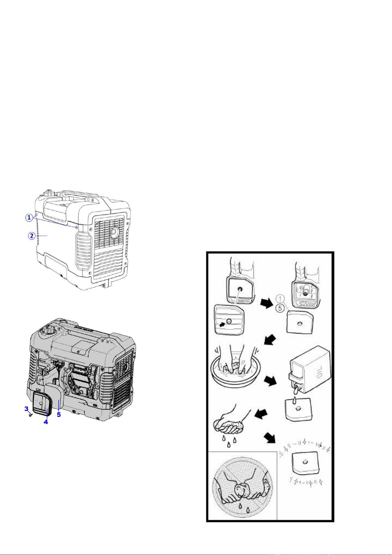
2. Remove the screws ① and then
remove the access panel ②.
Fig.53
3. Unscrew the dipstick from the engine
and set aside.
4. Place an oil pan under the engine.
Tilt the generator to drain the used oil
from the engine completely.Tilt some
more to ensure all oil is out of the
crankcase.
Fig.54
5. Replace the generator on a level
surface.Keep generator level!
CAUTION
Do not tilt the generator when adding
engine oil. Tilting the generator to assist
in filling will cause oil to flow into engine
areas and will cause damage. Keep
generator level!
6. Fill the crankcase with fresh oil.
Using a funnel or appropriate dispenser,
add the correct amount of oil into the
crankcase. The engine is equipped with
a low oil pressure sensor and will not
start if the amount of oil is insufficient.
Fig.55
7. Reinstall the dipstick.
CAUTION
Be sure no foreign material enters the
crankcase.
8. Clean any oil spillage before closing
the side panel.
9. Install the access panel and tighten the
screws.
NOTE:Never dispose of used motor oil
in the trash or down a drain. Please call a
local recycling center or auto garage to
arrange oil disposal.
DRAINING THE FUEL TANK
Clean fuel tank each year or before
storing the generator for extended
periods of time. To drain the fuel tank
and carburettor:
1. Turn the engine switch to “STOP”.
Fig.56
2. Remove the fuel tank cap, remove the
filter .Carefully turn the generator over
to pour the gasoline in the fuel tank to
appropriate container.
3. Once fuel is drained, reinstall the fuel
cap.
27
WARNING:
Fuel is highly flammable and poisonous.
see “SAFETY INFORMATION” section
carefully.
CAUTION
Immediately wipe off spilled fuel with a
clean, dry, soft cloth, since fuel may
deteriorate painted surfaces or plastic
parts.
4. Turn on the engine ( see “START THE
ENGINE” section) and keep the engine
running until it stops. This burns out the
fuel in the fuel tank. The engine stops in
approx. 20 minutes.
Fig.57
CAUTION
• Do not connect with any electrical
devices. (unloaded operation)
• Duration of the running engine
depends on the amount of the fuel left
in the tank.
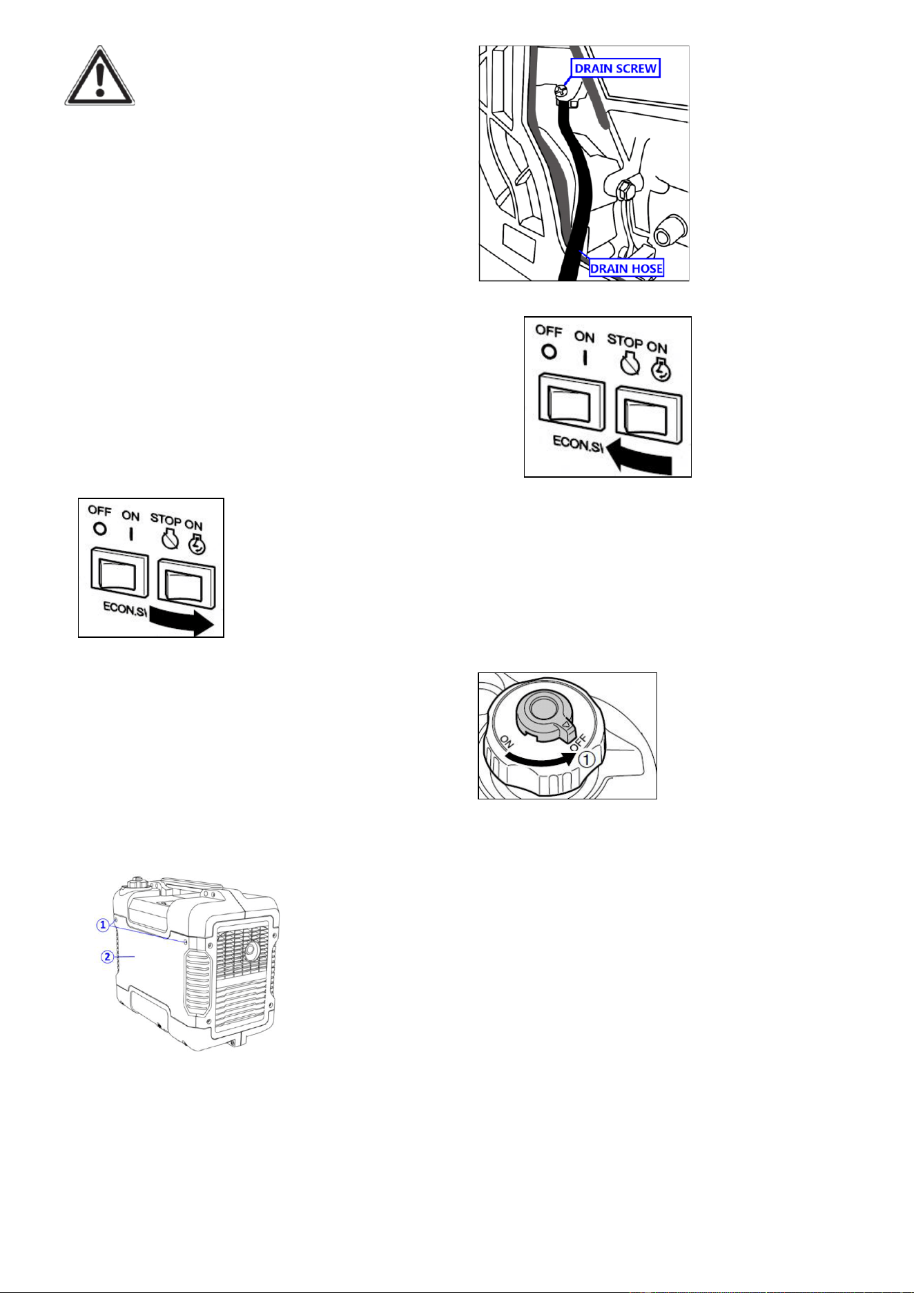
5. Remove the screws ①, and then
remove the access panel ②.
Fig.58
6. Drain the fuel from the carburetor by
loosening the drain screw on the
carburetor float chamber.
Fig.59
7. Turn the engine switch to “STOP”.
Fig.60
8. Retighten the drain screw.
9. Reinstall the access panel and tighten
the screws
10. Turn the fuel tank cap air vent knob
to “OFF” after the engine has
completely cools down.
Fig.61
11. Store the emptied gasoline in a
suitable place.
CAUTION:Do not store fuel for more
than 3 months.
SPARK PLUG INSPECTION
The spark plug is important for proper
engine operation, which should be
checked periodically. A good spark plug
should be intact, free of deposits, and
properly gapped. Refer to Recommended
Maintenance Schedule in Fig51. To
inspect the spark plug:
28
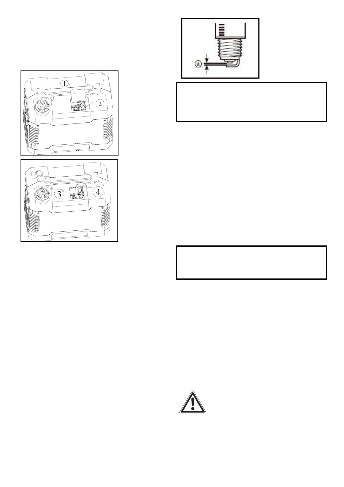
1. Remove the cover ①
2. Remove spark plug boot②. Be careful
not to tear insulation or wire and Insert
the tool ④ through the hole from the
outside of the cover.
Fig62
Fig.63
3. Insert the handlebar ③ into the tool
④,Unscrew the spark plug
counterclockwise from the engine using
the spark plug wrench provided. There is
limited space for the wrench to turn. Use
both rows of holes in the spark plug
wrench to gain leverage to loosen the
plug.
4. Visually inspect the spark plug for
cracks or excessive electrode wear.
Replace as necessary.Remove the carbon.
The porcelain insulator around the center
electrode of spark plug should be a
medium-to-light tan color.
5. Measure the plug gap with a wire
thickness gauge. The gap should be
0.6-0.7 mm (0.024-0.028 in).
Fig.64
Standard Spark Plug: E6TC/E6RTC
Spark Plug Gap: 0.6-0.7mm
(0.024-0.028in)
6. If re-using the spark plug, use a wire
brush to clean any dirt from around the
spark plug base then re-gap the spark
plug.
7. Install the spark plug: Screw the spark
plug back into the spark plug hole using
the spark plug wrench. Do not
over-tighten spark plug. Recommended
tightening of spark plug is1/2 to 3/4of a
turn after spark plug gasket contacts
spark plug hole.
Spark Plug Torque: 20.0 N*m
(2.0kgf*m, 14.8
lbf*ft)
NOTE: If a torque wrench is not
available when installing a spark plug, a
good estimate of the correct torque is
1/4-1/2 turn past finger tight. However,
the spark plug should be tightened to the
specified torque as soon as possible.
8. Reinstall the spark plug boot and spark
plug cover.
CARBURETOR ADJUSTMENT
WARNING
The carburetor is a vital part of the
engine. Adjusting should be left to our
company authorized dealer with the
professional knowledge, specialized date,
and equipment to do so properly.
29
Air filter
Routine maintenance of the air cleaner
helps maintain proper airflow to the
carburettor. Occasionally check that the
air cleaner is free of excessive dirt. Refer
to Recommended Maintenance Schedule
in Fig.51.
CAUTION: running the engine with
dirty, damaged or missing air cleaner
element will cause the engine to wear
out prematurely.
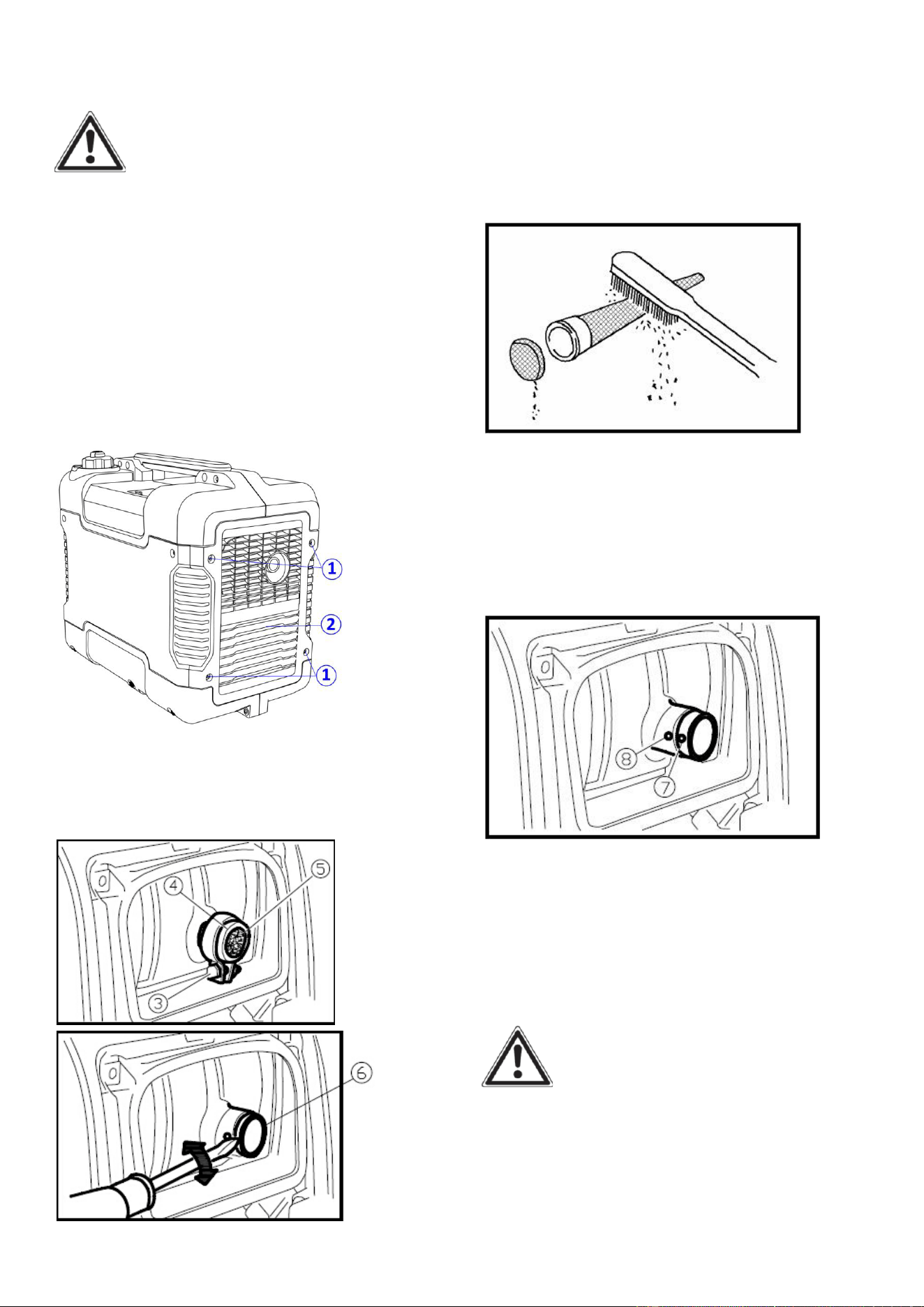
1. Remove the screws ①, and then
remove the access panel ②.
Fig.65
2. Remove the screw ③ and then
remove the air filter case cover ④.
Fig.66
3. Remove the foam element ⑤.
4. Check and clean the air filter element,
replace with a new one if the element is
damaged.
5. Good element can be washed in soapy
water, dried and reused.
CAUTION
Do not wring out the foam element when
squeezing it. This could cause it to tear.
6. Oil the foam element and squeeze out
excess oil.
7. Wipe off excessive oil from the air
cleaner case. Small amount of oil in the
element is normal and necessary for the
engine to work properly.
8. Insert the foam element into the air
filter case.
NOTE: Be sure the foam element
sealing surface. Matcher the air filter so
there is no air leak. The engine should
never run without the foam element;
excessive piston and cylinder wear may
result.
9. Install the air filter case cover in its
original position and tighten the screw.
10. Install the access panel and tighten
the screws.
Fig.67
30
MUFFLER SCREEN AND SPARK
ARRESTER
WARNING
The engine and muffler will be very hot
after the engine has been run. Avoid
touching the engine and muffler while
they are still hot with any part of your
body or clothing during inspection or
repair.
1. Remove the screws ①, and then pull
outward on the areas of the cover
②shown.
Fig.68
2. Loosen the bolt ③ and then remove
the muffler cap ④, the muffler
screen⑤ and spark arrester ⑥.
Fig.69
Fig.70
3. Clean the carbon deposits on the
muffler screen and spark arrester using a
wire brush.
CAUTION
When cleaning, use the wire brush
lightly to avoid damaging or scratching
of muffler screen and spark arrester.
Fig.71
4. Check the muffler screen and spark
arrester. Replace them if damaged.
5. Install the spark arrester.
NOTE:
Align the spark arrester projection ⑦
with the hole ⑧ in the muffler pipe.
Fig.72
6. Install the muffler screen and the
muffler cap.
7. Install the cover and tighten the
screws.
FUEL TANK FILTER
WARNING
Never use the gasoline while smoking or
in the vicinity of an open flame.
1. Remove the fuel tank cap and filter.
2. Clean the filter with gasoline.
3. Wipe the filter and install it.
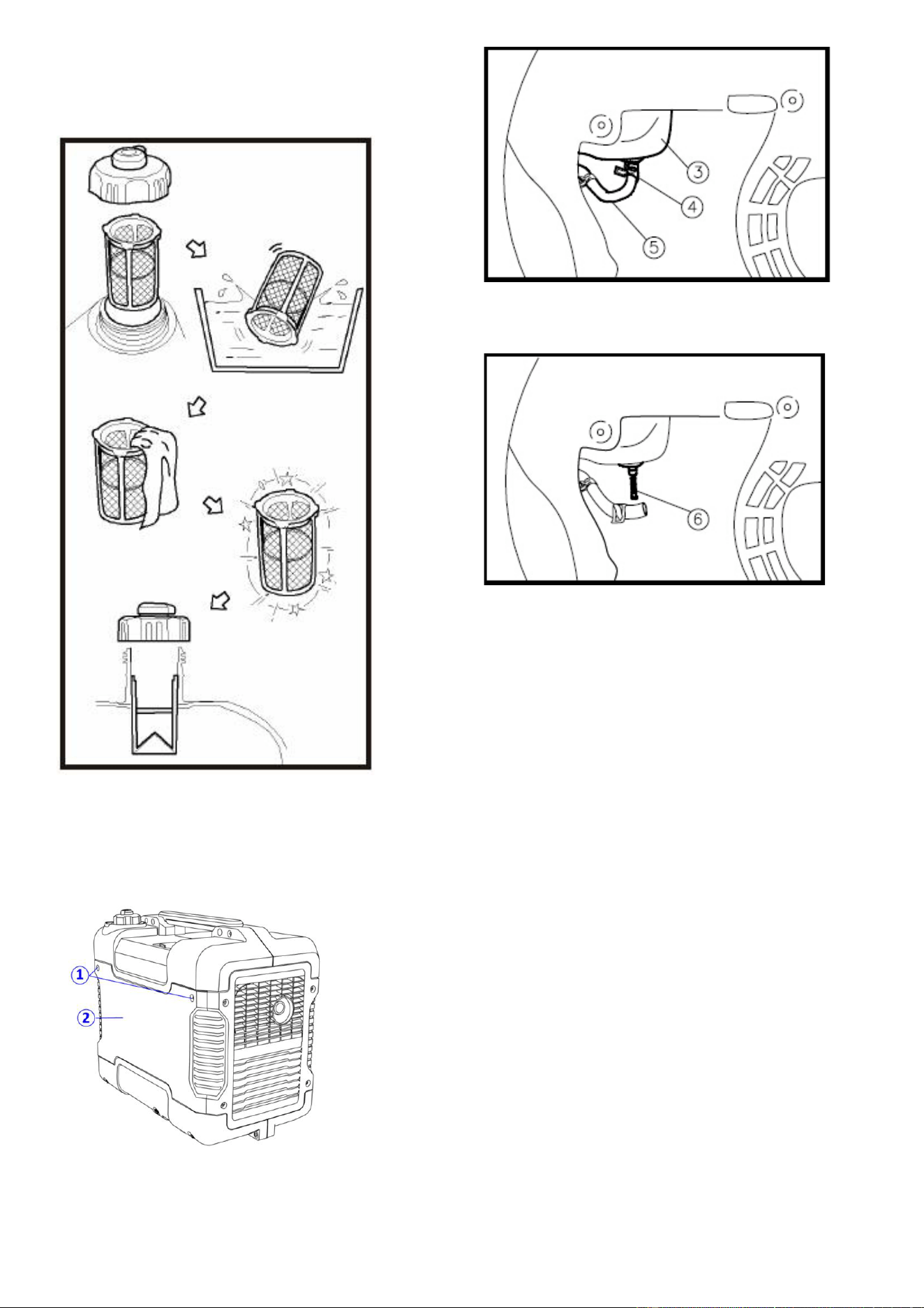
31
4. Install the fuel tank cap.
NOTE: Be sure the fuel tank cap is
tightened securely.
Fig.73
Fuel filter
1. Remove the screws ①, and then
remove the access panel ②, and drain
the fuel③.
Fig.74
2. Hold and move up the clamp ④, then
take off the hose ⑤ from the tank.
Fig.75
3. Take out the fuel filter ⑥.
Fig.76
4. Clean the filter with gasoline.
5. Dry the filter and put it back into tank.
6. Install the hose and clamp, then open
the fuel valve to check whether it is
leak.
7. Reinstall the cover and tighten the
screws.
STORAGE
STORAGE & TRANSPORT
PROCEDURES
CAUTION: Never place any type of
storage cover on the generator while it is
still hot.
If the generator is being stored for short
periods of time over 30 days , add
stabilized fuel to the fuel tank until full.
NOTE: Filling the tank reduces the
amount of air in the tank and helps
reduce deterioration of fuel. Run the
engine for 2 - 3 minutes allowing

32
stabilized fuel mixture to circulate
through the carburettor.
When storing the generator for extended
periods of time:
• Drain the fuel tank (see “Draining the
Fuel Tank” in the “Maintenance”
section).
• Drain the carburettor
• Change oil.
• Do not obstruct any ventilation
openings.
• Keep the generator in a cool dry area.
When transporting generator:
Tighten fuel cap and fuel tank cap air
vent knob. Drain the fuel tank if
possible (see “Draining the Fuel Tank”
in the “Storage” section).
Keep the generator upright. Never
place the generator side down. Doing
so will make it difficult to start.
Long term storage of your machine will
require some preventive procedures to
guard against deterioration.
In order to prevent corrosion, please coat
antirust oil on all screw, at least once half
one year.
ENGINE
Perform the following steps to protect
the cylinder, piston ring, etc. from
corrosion.
1. Remove the spark plug, pour about
one table- spoon of SAE 10W-30 into the
spark plug hole and reinstall the spark
plug. Pull the Choke knob to out
position.Recoil start the engine by
turning over several times to coat the
cylinder walls with oil.
2. Pull the recoil starter until you feel
compression. Then stop pulling. (This
prevents the cylinder and valves from
rusting).
3. Clean exterior of the generator. Store
the generator in a dry, well-ventilated
place, with the cover placed over it.

33
TROUBLESHOOTING
IMPORTANT: If trouble persists, please call our customer service center.
Problem
Cause
Solution
Engine
will not
start
Engine switch in “OFF” position
Set engine switch to “ON” position.
PulltheChoke knobfully out
when warm start
Pressthe choke knobfully in
Engine is filledwith
contaminated or old fuel
Change the fuel in the tank.
Not enough oil in crankcase
Add or replaceengineoil.
Airfilteris dirty.
Clean or replace airfilter.
Spark plug is dirtyor wet
Remove carbon or wipe spark plug dry.
Spark plug isbroken.
Replace spark plug.
Generator is not on level
surface
Move generator to a level surface to prevent low
oil shutdown from triggering.
Engine needs maintenance
Get a professional engine tune-up at an
authorized small engine repair shop
Generator was tilted when
adding oil, or shipped
side-down
Remove spark plugs, turn off engine switch then
pull recoil starter four times to remove oil from
the combustion chamber.
Fuel systems:No fuel supplied to combustion chamber
1 No fuel in tank
Refuel
2 Fuel in tank
Set fuel tank cap air vent knob and fuel cock
knob to “ON”
3 Clogged fuel filter
Clean fuel filter
4 Clogged carburettor
Clean carburettor
Faulty ignition system
Consult service center
Engine
stops
Fuel tank cap air vent knobin
“OFF” position
TurnFuel tank cap air vent knobto “ON” position
Not enough oil in crankcase
Add or change oil
Engine is out of fuel
Add fuel.
Blue
smoke in
exhaust
Generator inclined, oil entered
combustion chamber
Move generator to a levelposition
Too much oil was added to the
crankcase.
Drain excessive oil.

34
Generator
runs but
does not
support all
electrical
devices
connected.
Bad connecting wires/cables.
If using an extension cord, try a different one.
Bad electrical device
connected to generator.
Try connecting a different device
Generator is overloaded,
Overload light is on
Perform these steps: 1. Turn off all electrical
devices. 2. Unplug all electrical devices. 3. Shut
down the engine. 4. Wait several minutes and
thenstart the engine. 5. Try connecting fewer
electrical loads to the generator.
Short in one of the connected
devices.
Try disconnecting any faulty or short-circuited
electrical loads.
Generator
does not
produce
power
Safety device (DC protector)
to “OFF”
Press the DC protector to “ON”
The AC pilot light (Green)
go off
Stop the engine, then restart
35
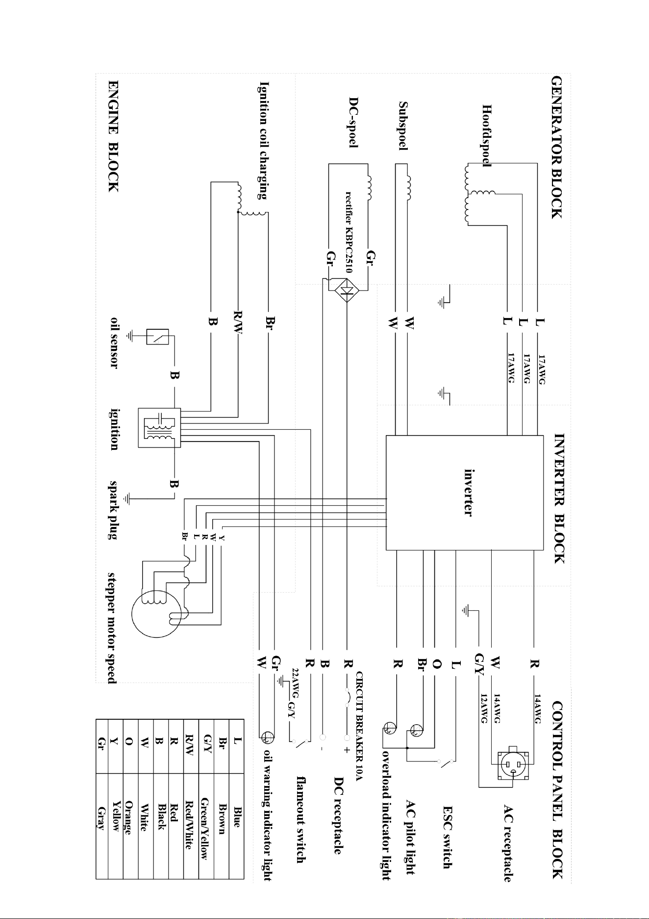
WIRING DIAGRAM
36
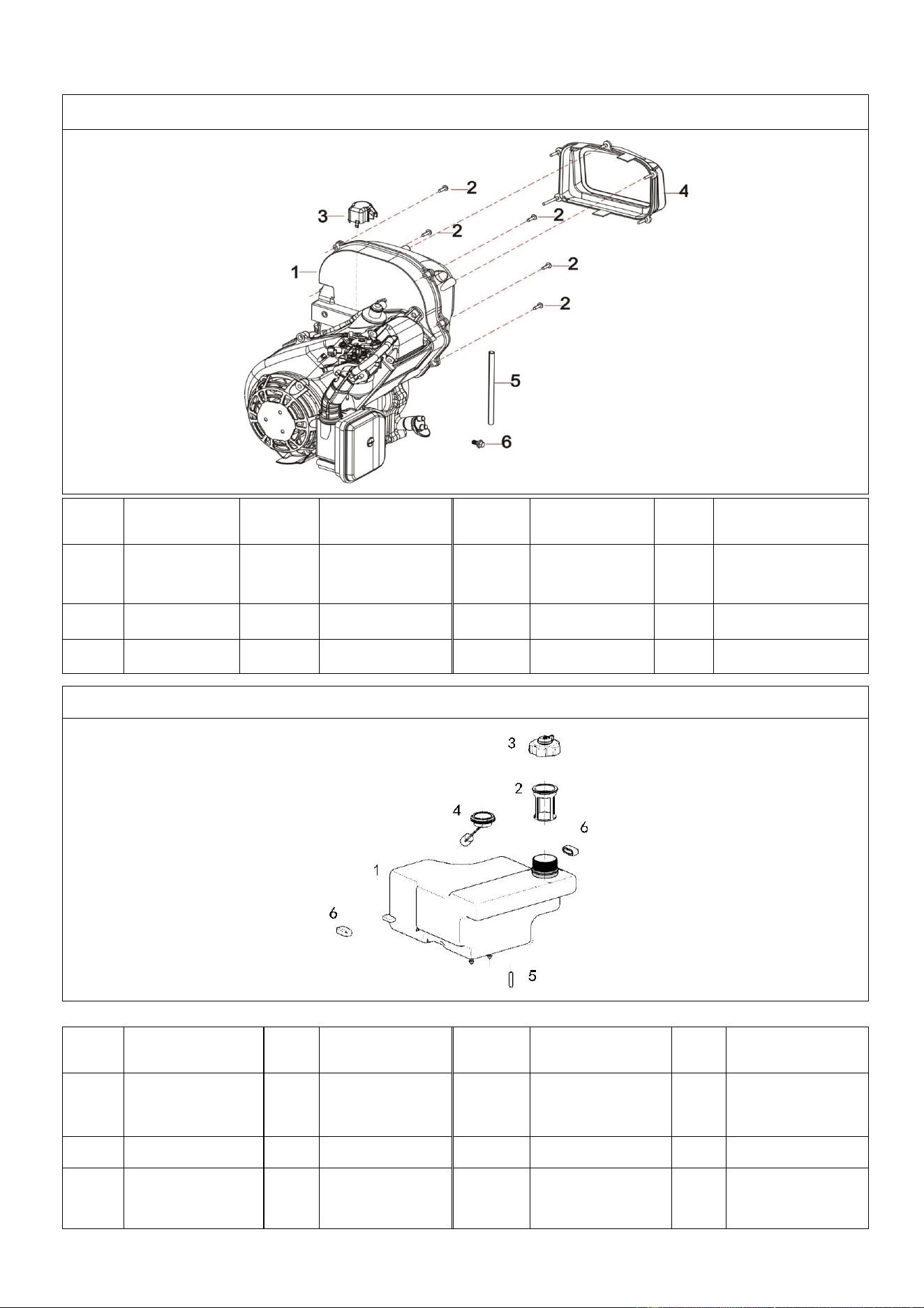
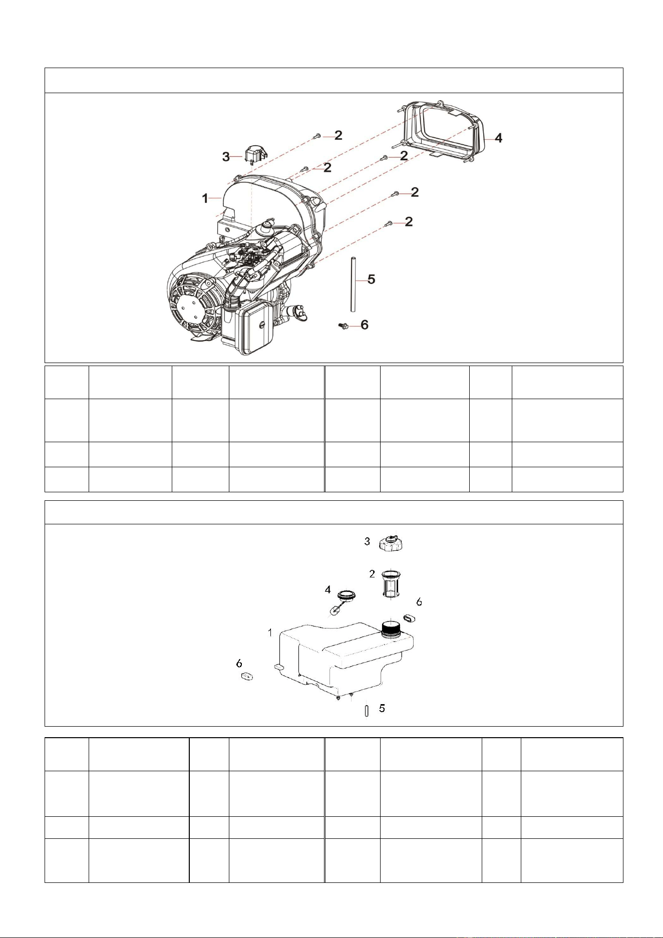
A112001 EXPLODED VIEW AND PART LIST
FIG.1 Engine (E00)
Refe#
Description
Qty/pc
Stock#
Refe#
Description
Qty/
pc
Stock#
1-1
Engine
1
A112001-1-1
1-4
Muffler
Cover
1
A112001-1-4
1-2
Tapping
Screw
5
A112001-1-2
1-5
Fuel Pipe
1
A112001-1-5
1-3
Cap
1
A112001-1-3
1-6
Flange Bolt
1
A112001-1-6
FIG.2 Tank, Fuel (F01)
Refe#
Description
Qty/
pc
Stock#
Refe#
Description
Qty/
pc
Stock#
2-1
Fuel Tank
Assy
1
A112001-2-1
2-4
Fuel Level
Gauge
1
A112001-2-4
2-2
Fuel Filter
1
A112001-2-2
2-5
Filter Element
1
A112001-2-5
2-3
Cap
1
A112001-2-3
2-6
10# Rubber
Parts
2
A112001-2-6

37
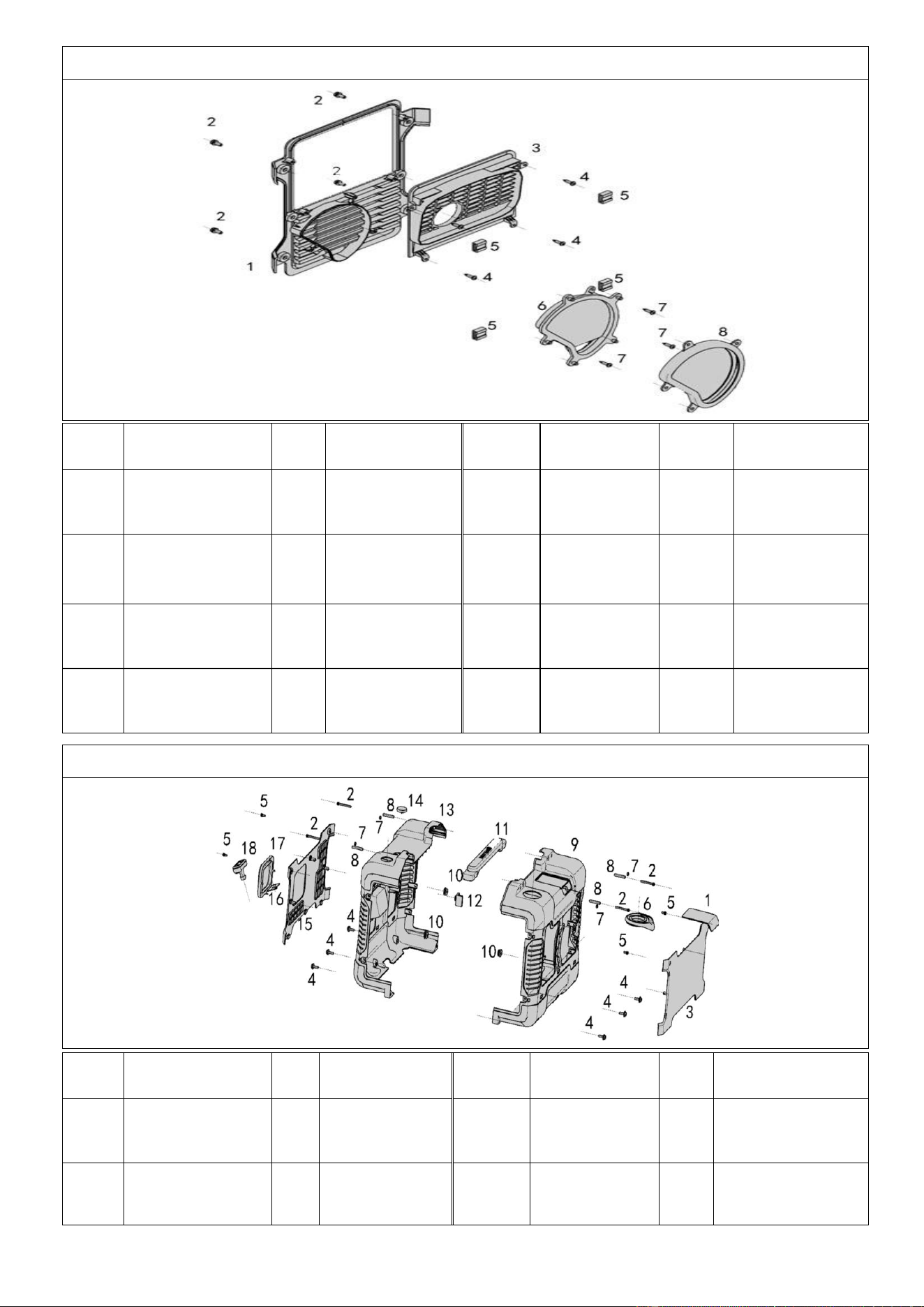
FIG.3 Muffler Cover (F61)
Refe#
Description
Qty/
pc
Stock#
Refe#
Description
Qty/pc
Stock#
3-1
Muffler Cover
Support
1
A112001-3-1
3-5
Clip Nut
4
A112001-3-5
3-2
Cross Pan
Bolts
4
A112001-3-2
3-6
Alternator
Cover
1
A112001-3-6
3-3
Muffle Cover
1
A112001-3-3
3-7
Tapping
Screw
3
A112001-3-7
3-4
Tapping
Screw
4
A112001-3-4
3-8
5# Rubber
Parts
1
A112001-3-8
FIG.4 Cover and Panel(F61)
Refe#
Description
Qty
/pc
Stock#
Refe#
Description
Qty/
pc
Stock#
4-1
Spark Plug
Cover
1
A112001-4-1
4-10
11# Rubber
Part
6
A112001-4-10
4-2
Assembled
Bolt
4
A112001-4-2
4-11
Handle A-B
1
A112001-4-11
38
4-3
Back Panel
1
A112001-4-3
4-12
Rubber
Parts
1
A112001-4-12
4-4
M6x20 Flange
Bolt
6
A112001-4-4
4-13
Front
Housing
1
A112001-4-13
4-5
M6x10 Flange
Bolt
4
A112001-4-5
4-14
Viewing
Mirror
1
A112001-4-14
4-6
4# Rubber
Parts
1
A112001-4-6
4-15
Front Board
1
A112001-4-15
4-7
M5 Nut
4
A112001-4-7
4-16
Recoil Baffle
1
A112001-4-16
4-8
Bushing
4
A112001-4-8
4-17
Frame
1
A112001-4-17
4-9
Back Housing
1
A112001-4-9
4-18
Starter
1
A112001-4-18
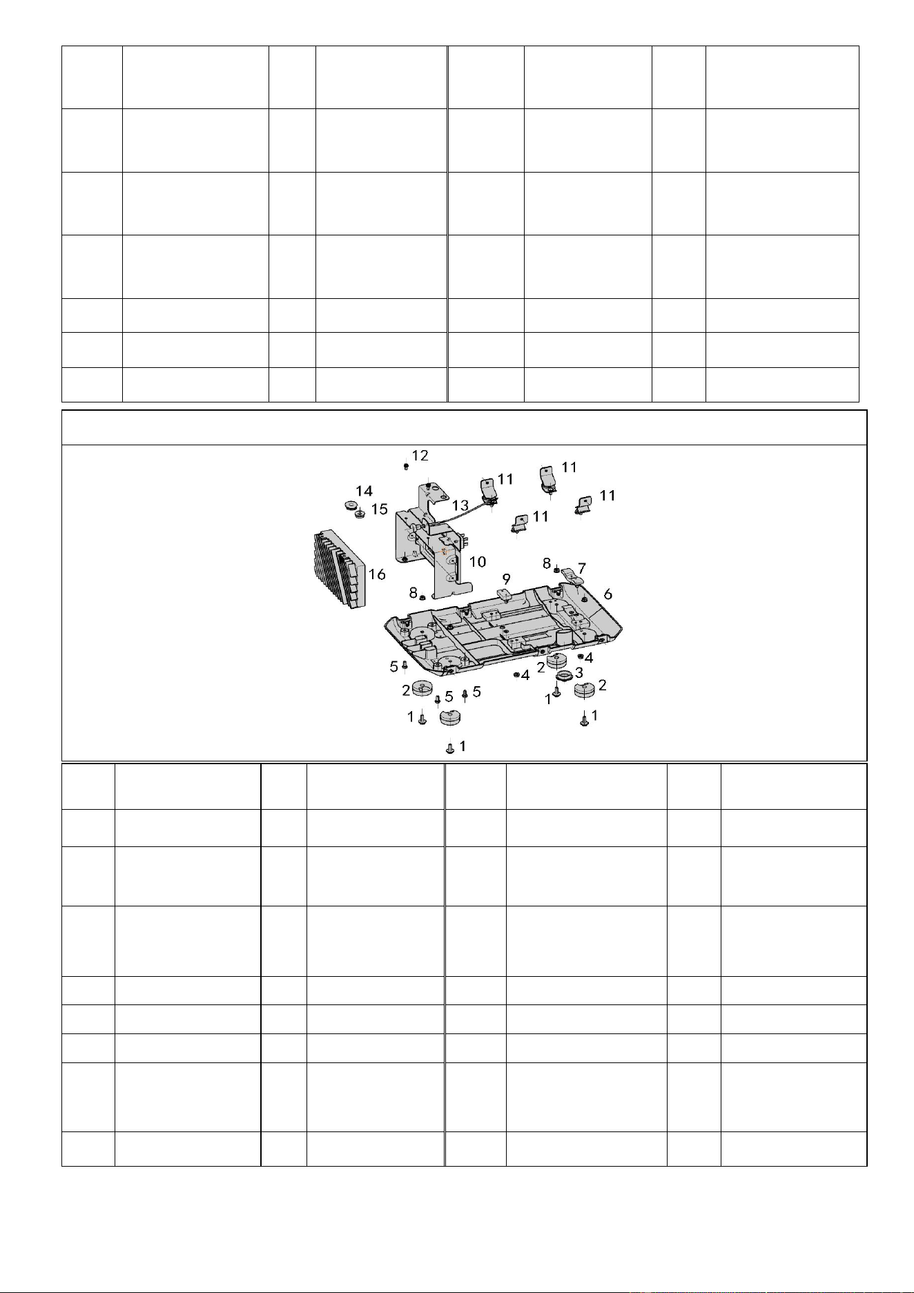
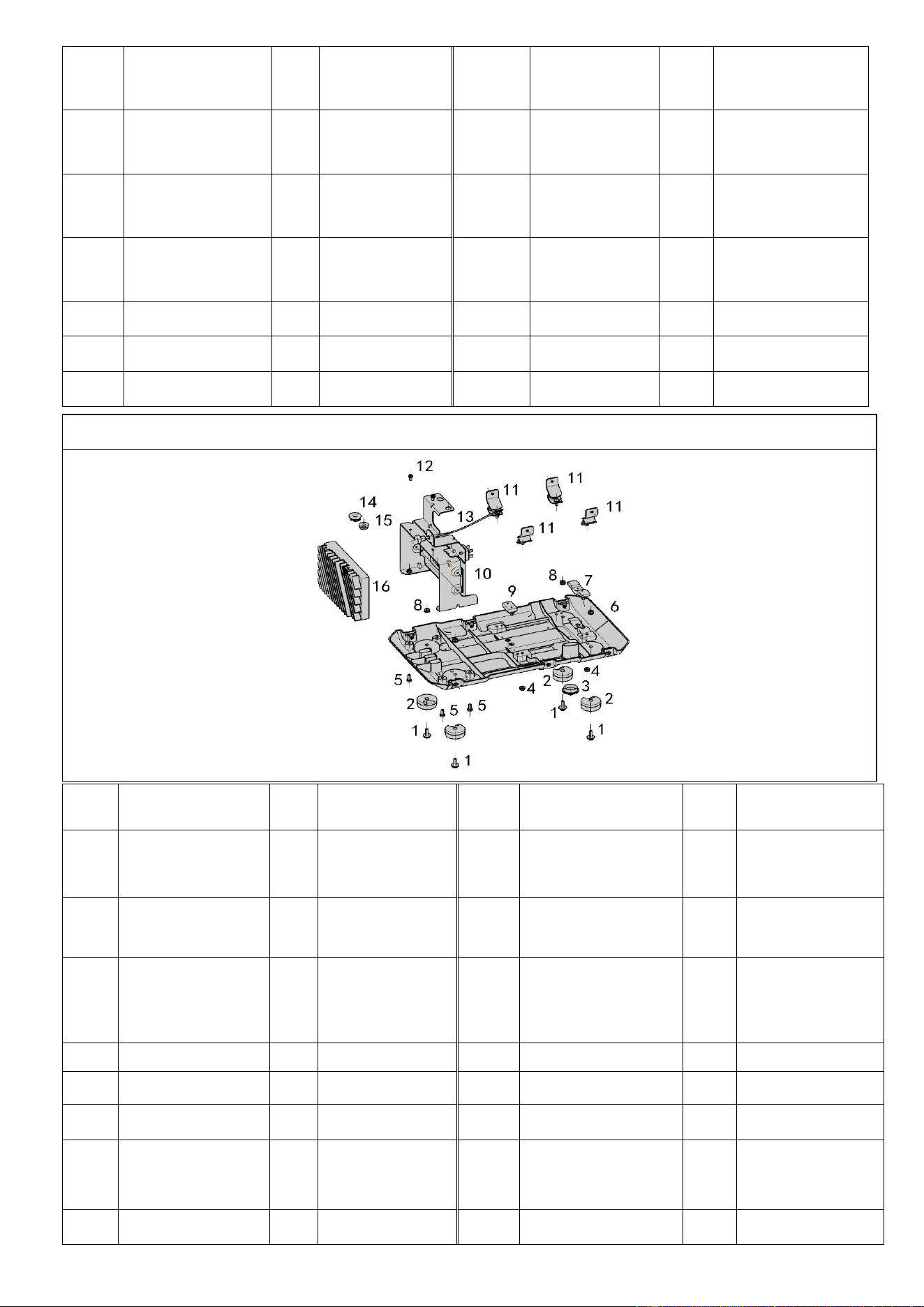
FIG.5 Baseplate,Inverter And Inverter Frame (F61)
Refe
#
Description
Qty
/pc
Stock#
Refe#
Description
Qty/
pc
Stock#
5-1
M6X18 Screw
4
A112001-5-1
5-9
13# Rubber Part
1
A112001-5-9
5-2
3# Rubber
Parts
4
A112001-5-2
5-10
Iron Support
1
A112001-5-10
5-3
7# Rubber
Parts
1
A112001-5-3
5-11
Shock
AbsorptionFoot
1
A112001-5-11
5-4
M6 Flange
Nut
4
A112001-5-4
5-12
M6X18 Screw
2
A112001-5-12
5-5
M5X15 Bolt
4
A112001-5-5
5-13
Throttle Cable
1
A112001-5-13
5-6
Baseboard
1
A112001-5-6
5-14
6# Rubber Part
1
A112001-5-14
5-7
12# Rubber
Part
1
A112001-5-7
5-15
11# Rubber
Part
1
A112001-5-15
5-8
M6 Flange
Nut
4
A112001-5-8
5-16
Inverter Unit
1
A112001-5-16
39
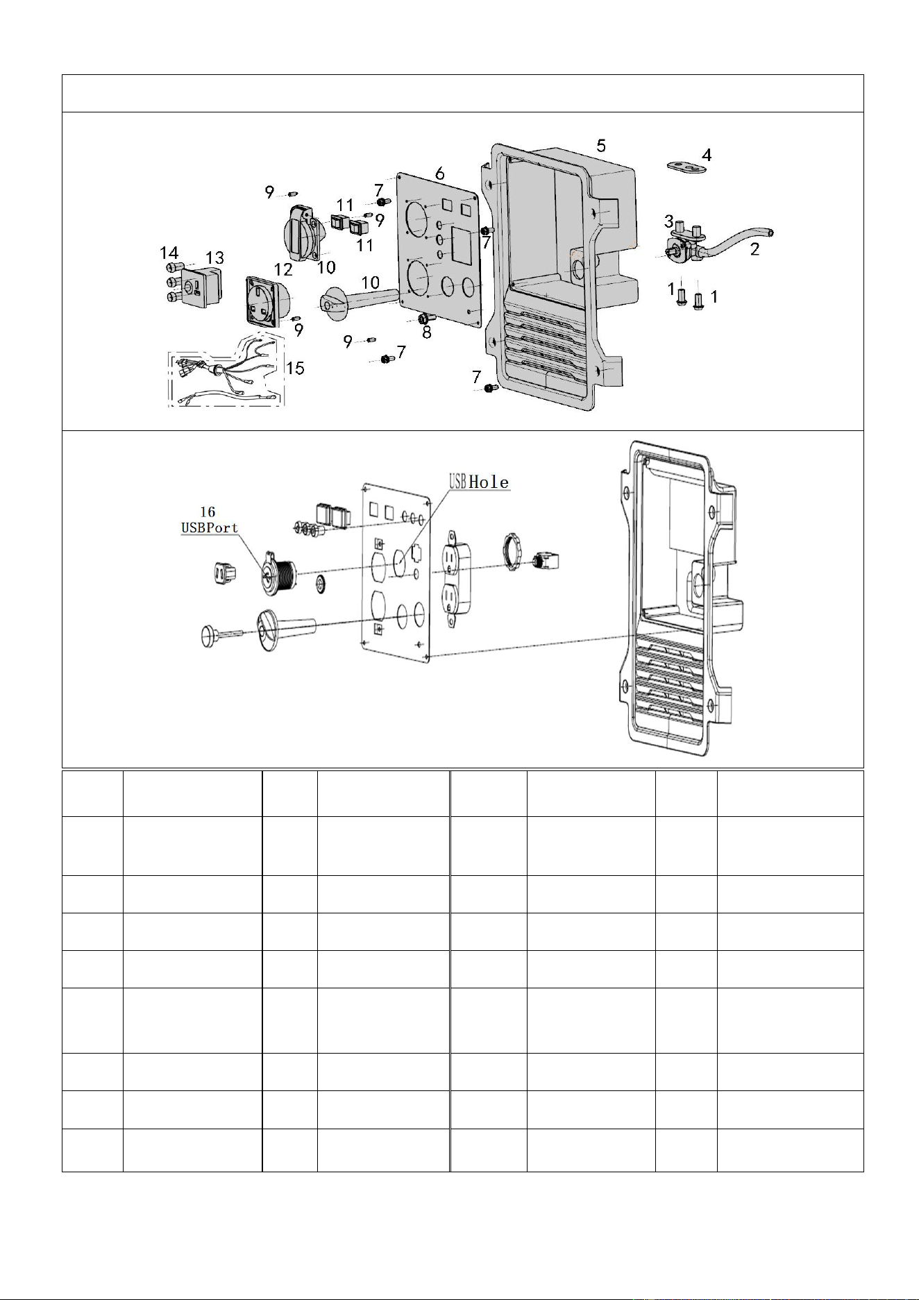
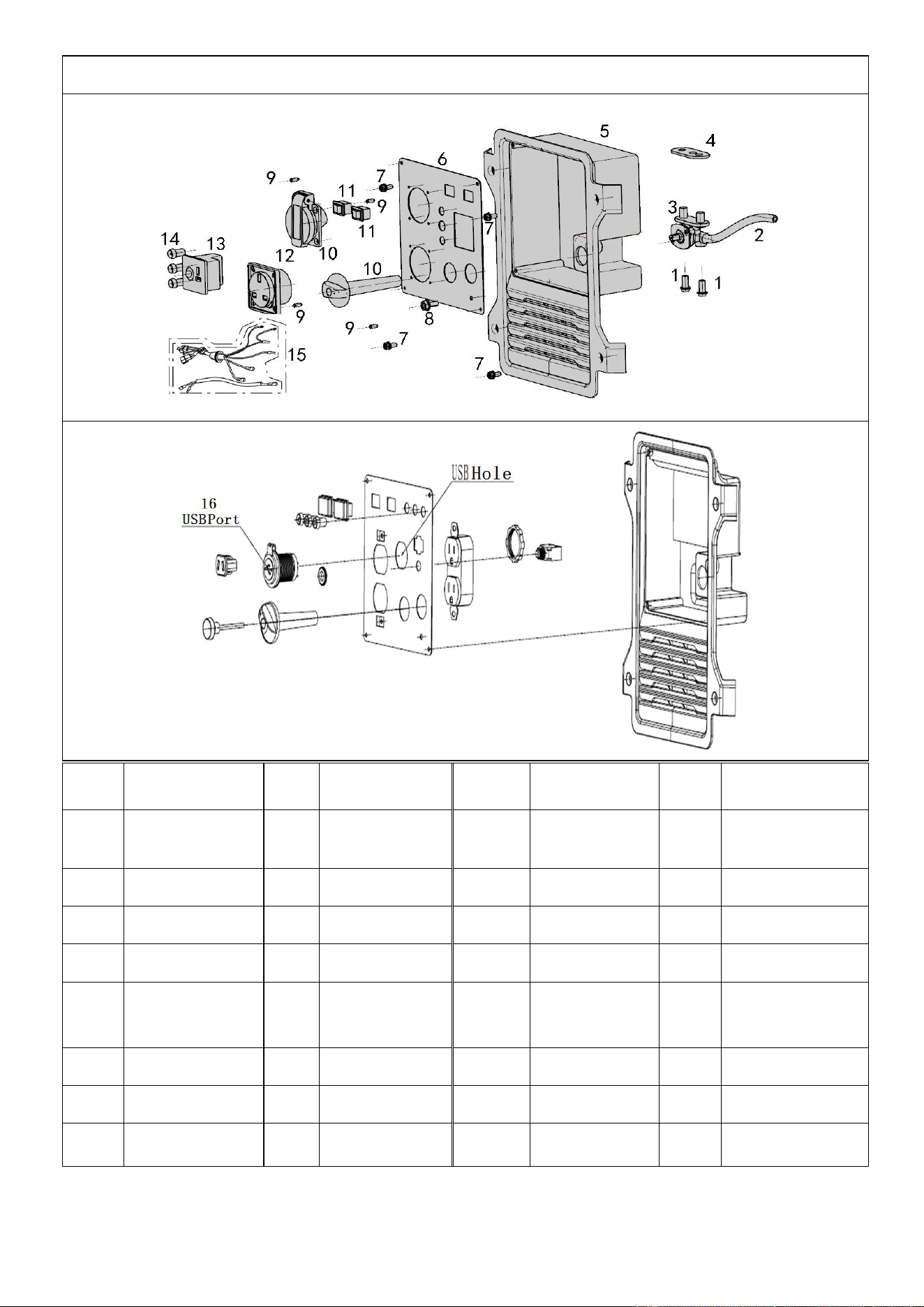
FIG.6 Control Panel (F62)
Refe#
Description
Qty/
pc
Stock#
Refe#
Description
Qty/
pc
Stock#
6-1
Cross Bolt
2
A112001-6-1
6-9
Tapping
Screw
4
A112001-6-9
6-2
Fuel Pipe
1
A112001-6-2
6-10
Socket
1
A112001-6-10
6-3
Fuel Switch
1
A112001-6-3
6-11
Switch
1
A112001-6-11
6-4
Shim
1
A112001-6-4
6-12
Socket
1
A112001-6-12
6-5
Panel
Housing
1
A112001-6-5
6-13
DC Charger
Socket
1
A112001-6-13
6-6
Panel
1
A112001-6-6
6-14
Pilot Light
3
A112001-6-14
6-7
Cross Screw
4
A112001-6-7
6-15
Cable
1
A112001-6-15
6-8
Cross Screw
1
A112001-6-8
6-16
USB Port
1
A112001-6-16
40
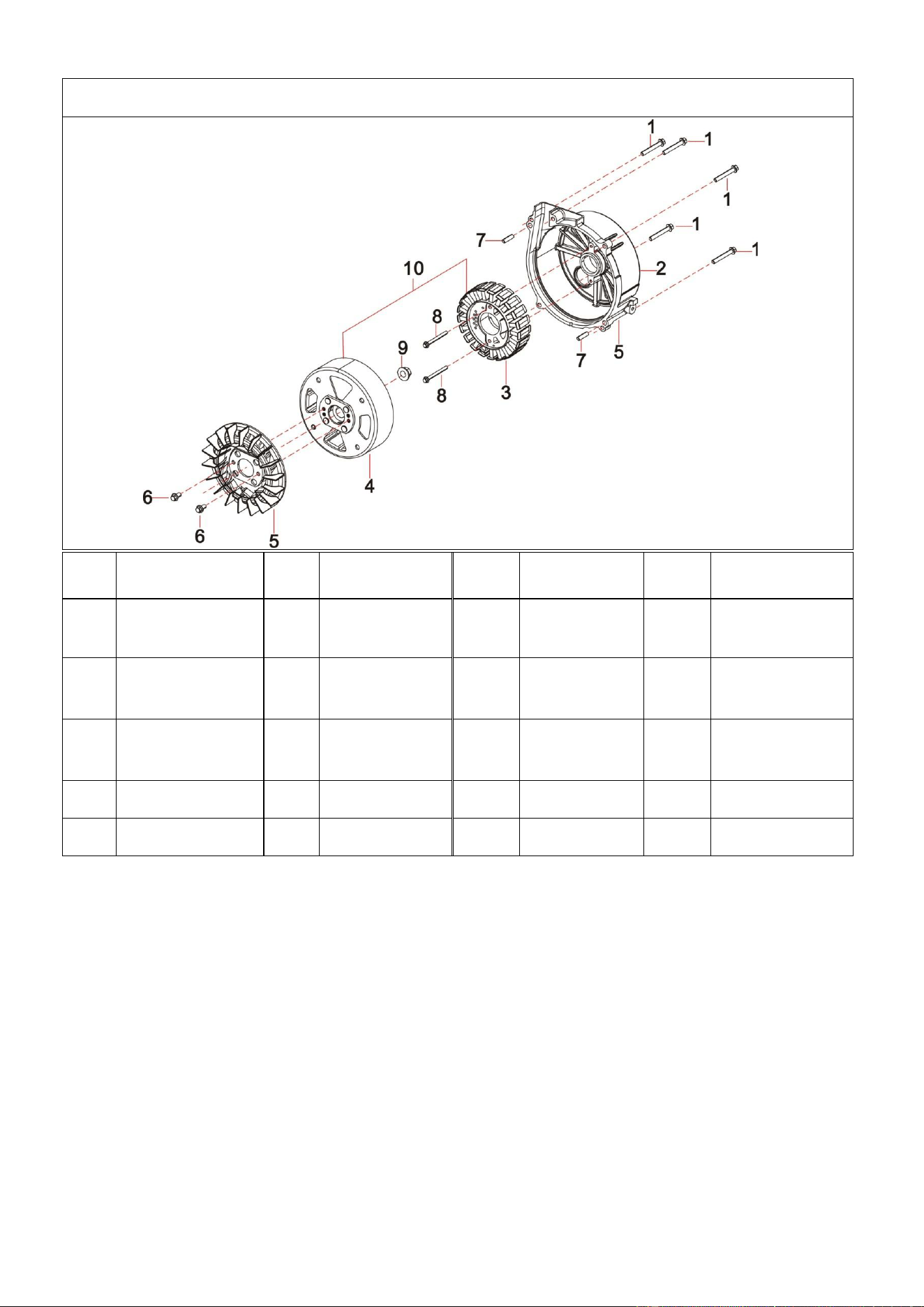
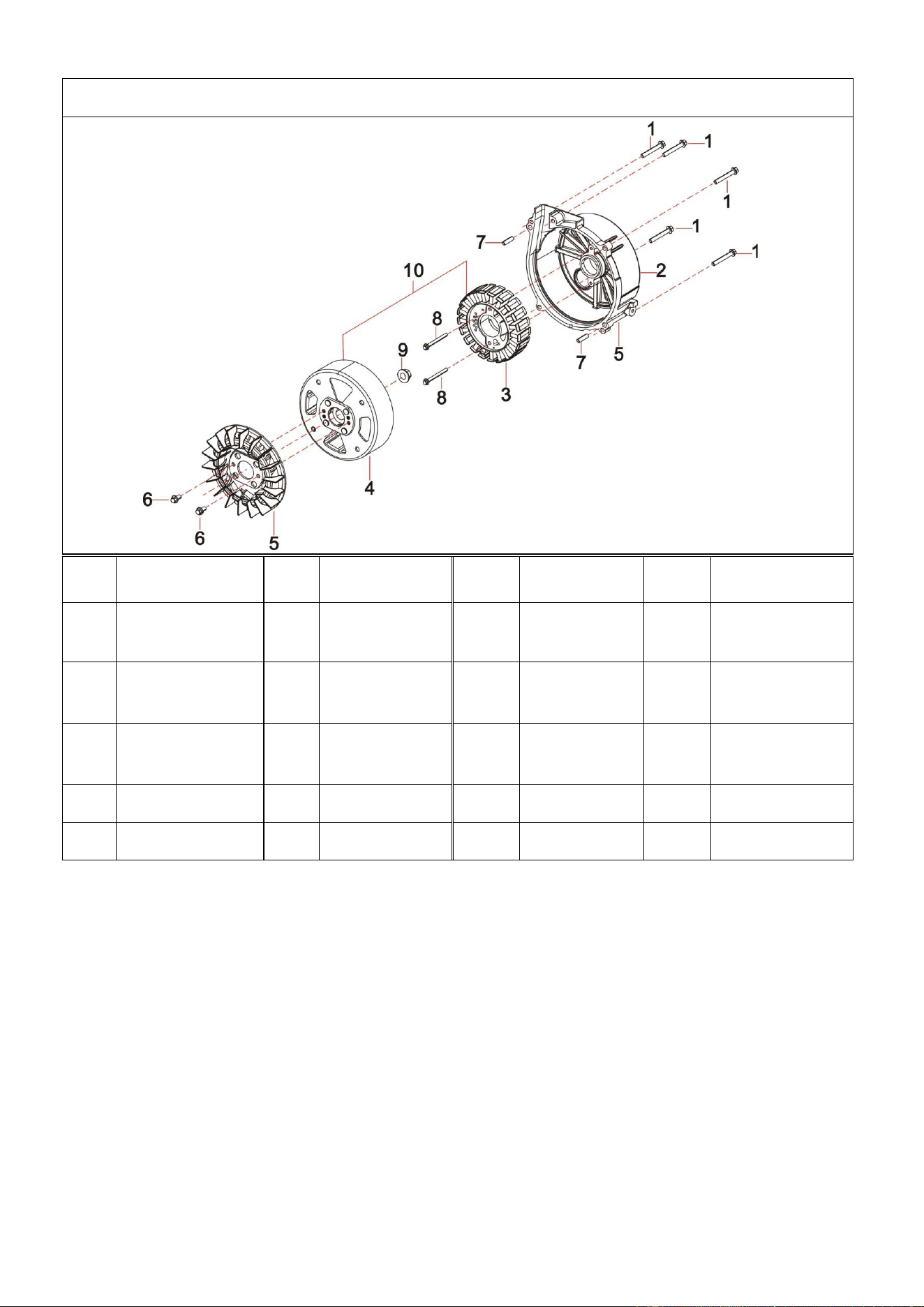
FIG.7 Rotor/Stator (F63)
Refe
#
Description
Qty/
pc
Stock#
Refe#
Description
Qty/p
c
Stock#
7-1
Flange Bolt
5
A112001-7-1
7-6
Flange
Bolt
2
A112001-7-6
7-2
Alternator
Cover
1
A112001-7-2
7-7
Pin
2
A112001-7-7
7-3
Stator ASSY
1
A112001-7-3
7-8
Flange
Bolt
2
A112001-7-8
7-4
Rotor ASSY
1
A112001-7-4
7-9
Flange Nut
1
A112001-7-9
7-5
Fan
1
A112001-7-5
7-10
Alternator
1
A112001-7-1
0
41
A112002 EXPLODED VIEW AND PART LIST
FIG.1 Engine (E00)
Refe#
Description
Qty/pc
Stock#
Refe#
Description
Qty/
pc
Stock#
1-1
Engine
1
A112002-1-1
1-4
Muffler
Cover
1
A112002-1-4
1-2
Tapping
Screw
5
A112002-1-2
1-5
Fuel Pipe
1
A112002-1-5
1-3
Cap
1
A112002-1-3
1-6
Flange Bolt
1
A112002-1-6
FIG.2 Tank, Fuel (F01)
Refe#
Description
Qty/
pc
Stock#
Refe#
Description
Qty/
pc
Stock#
2-1
Fuel Tank
Assy
1
A112002-2-1
2-4
Fuel Level
Gauge
1
A112002-2-4
2-2
Fuel Filter
1
A112002-2-2
2-5
Filter Element
1
A112002-2-5
2-3
Cap
1
A112002-2-3
2-6
10# Rubber
Parts
2
A112002-2-6
42
FIG.3 Muffler Cover (F61)
Refe#
Description
Qty/
pc
Stock#
Refe#
Description
Qty/pc
Stock#
3-1
Muffler Cover
Support
1
A112002-3-1
3-5
Clip Nut
4
A112002-3-5
3-2
Cross Pan
Bolts
4
A112002-3-2
3-6
Alternator
Cover
1
A112002-3-6
3-3
Muffle Cover
1
A112002-3-3
3-7
Tapping
Screw
3
A112002-3-7
3-4
Tapping
Screw
4
A112002-3-4
3-8
5# Rubber
Parts
1
A112002-3-8
FIG.4 Cover and Panel(F61)
Refe#
Description
Qty
/pc
Stock#
Refe#
Description
Qty/
pc
Stock#
4-1
Spark Plug
Cover
1
A112002-4-1
4-10
11# Rubber
Part
6
A112002-4-10
4-2
Assembled
Bolt
4
A112002-4-2
4-11
Handle A-B
1
A112002-4-11
43
4-3
Back Panel
1
A112002-4-3
4-12
Rubber
Parts
1
A112002-4-12
4-4
M6x20 Flange
Bolt
6
A112002-4-4
4-13
Front
Housing
1
A112002-4-13
4-5
M6x10 Flange
Bolt
4
A112002-4-5
4-14
Viewing
Mirror
1
A112002-4-14
4-6
4# Rubber
Parts
1
A112002-4-6
4-15
Front Board
1
A112002-4-15
4-7
M5 Nut
4
A112002-4-7
4-16
Recoil Baffle
1
A112002-4-16
4-8
Bushing
4
A112002-4-8
4-17
Frame
1
A112002-4-17
4-9
Back Housing
1
A112002-4-9
4-18
Starter
1
A112002-4-18
FIG.5 Baseplate,Inverter And Inverter Frame (F61)
Refe
#
Description
Qty
/pc
Stock#
Refe#
Description
Qty/
pc
Stock#
5-1
M6X18 Screw
4
A112002-5-1
5-9
13# Rubber Part
1
A112002-5-9
5-2
3# Rubber
Parts
4
A112002-5-2
5-10
Iron Support
1
A112002-5-10
5-3
7# Rubber
Parts
1
A112002-5-3
5-11
Shock
AbsorptionFoot
1
A112002-5-11
5-4
M6 Flange Nut
4
A112002-5-4
5-12
M6X18 Screw
2
A112002-5-12
5-5
M5X15 Bolt
4
A112002-5-5
5-13
Throttle Cable
1
A112002-5-13
5-6
Baseboard
1
A112002-5-6
5-14
6# Rubber Part
1
A112002-5-14
5-7
12# Rubber
Part
1
A112002-5-7
5-15
11# Rubber
Part
1
A112002-5-15
5-8
M6 Flange Nut
4
A112002-5-8
5-16
Inverter Unit
1
A112002-5-16
44
FIG.6 Control Panel (F62)
Refe#
Description
Qty/
pc
Stock#
Refe#
Description
Qty/
pc
Stock#
6-1
Cross Bolt
2
A112002-6-1
6-9
Tapping
Screw
4
A112002-6-9
6-2
Fuel Pipe
1
A112002-6-2
6-10
Socket
1
A112002-6-10
6-3
Fuel Switch
1
A112002-6-3
6-11
Switch
1
A112002-6-11
6-4
Shim
1
A112002-6-4
6-12
Socket
1
A112002-6-12
6-5
Panel
Housing
1
A112002-6-5
6-13
DC Charger
Socket
1
A112002-6-13
6-6
Panel
1
A112002-6-6
6-14
Pilot Light
3
A112002-6-14
6-7
Cross Screw
4
A112002-6-7
6-15
Cable
1
A112002-6-15
6-8
Cross Screw
1
A112002-6-8
6-16
USB Port
1
A112002-6-16
45
FIG.7 Rotor/Stator (F63)
Refe
#
Description
Qty/
pc
Stock#
Refe#
Description
Qty/p
c
Stock#
7-1
Flange Bolt
5
A112002-7-1
7-6
Flange
Bolt
2
A112002-7-6
7-2
Alternator
Cover
1
A112002-7-2
7-7
Pin
2
A112002-7-7
7-3
Stator ASSY
1
A112002-7-3
7-8
Flange
Bolt
2
A112002-7-8
7-4
Rotor ASSY
1
A112002-7-4
7-9
Flange Nut
1
A112002-7-9
7-5
Fan
1
A112002-7-5
7-10
Alternator
1
A112002-7-1
0