s
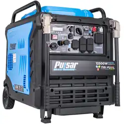
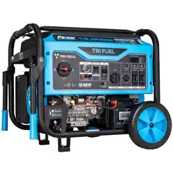
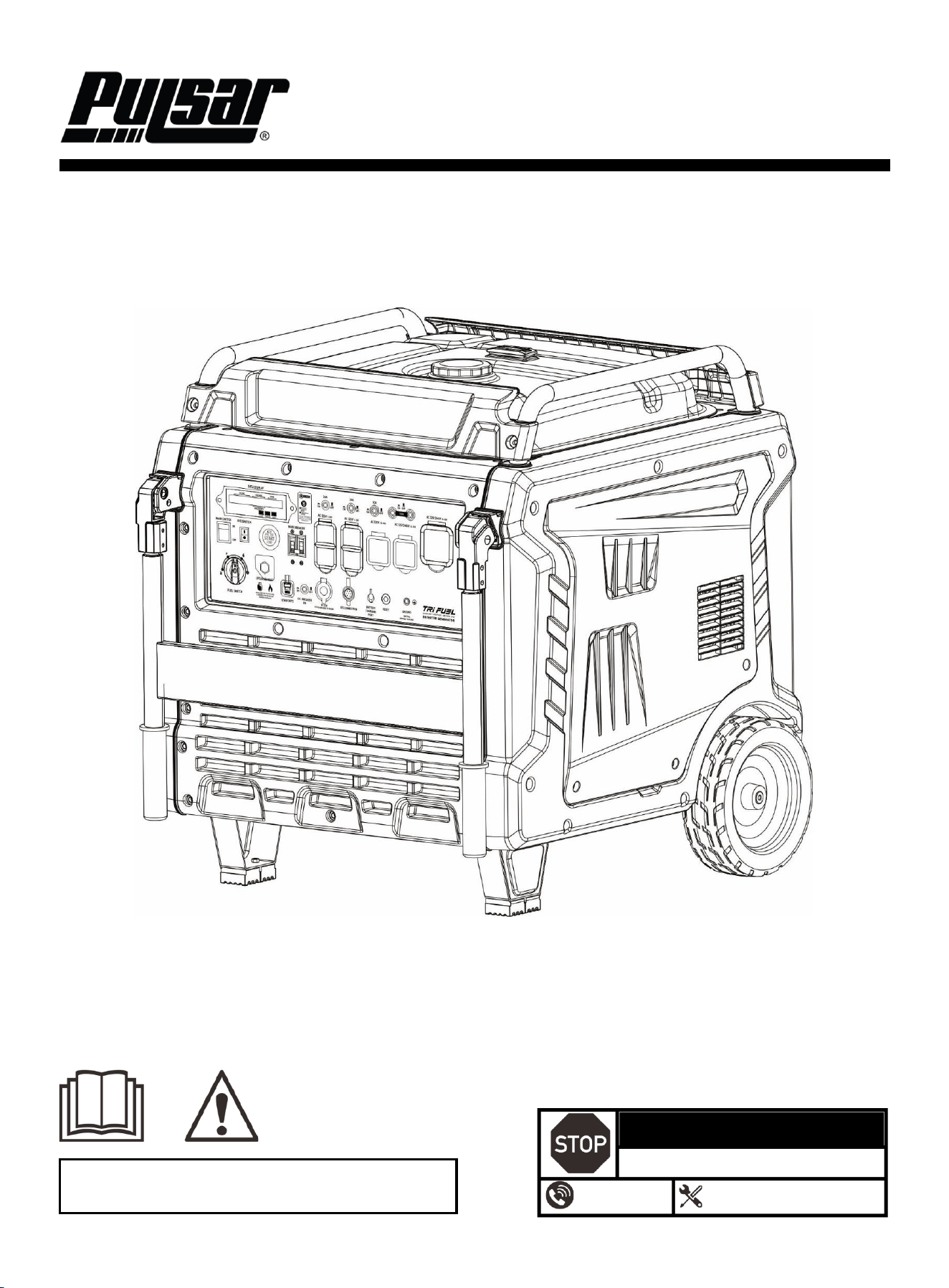
17000 Watt Tri-Fuel Inverter Generator
OPERATOR'S MANUAL
WARNING: This product contains chemicals, including lead, known to the State of
California to cause cancer, birth defects or other reproductive harm. Wash hands
after handling. For more information, visit www.P65warnings.ca.gov.
DO NOT RETURN TO STORE!
HAVE QUESTIONS OR NEED SERVICE?
866-591-8921
support@pulsar-products.com
Model: PGD170TiSRCO
Caution:
⚫ Before using your generator, please read this manual carefully to understand proper use.
⚫ Keep this manual with the generator.
1
Table of Contents
Table of Contents ………………………………….…...…..1
Introduction .………………………………………….……..1
Safety Warnings and Notices ………………………...….1
Safety Instructions …………………………………………2
Components…………………………………………………4
Control Panel ……………………………………………..…5
Preparation………………………………………………………7
Operation.………………………………………………………12
Maintenance ………………………………………….……….16
Specifications ……………………….………………......……21
Troubleshooting Guide………….…….……………….….…22
Electrical Schematic……………………………………….…25
Introduction
Thank you for choosing Pulsar Products!
This manual provides instructions on how to safely and
correctly operate your generator. Please read and fully
understand this manual before using your generator. If you
have any questions, contact us at 866.591.8921 (Monday–
Friday) or at support@pulsar-products.com before using
your generator.
All details and images in this manual are believed to be
accurate at the time of publication. Pulsar Products
reserves the right to make updates to this manual at any
time. For the latest updates, please contact Pulsar Support
at 866.591.8921 or support@pulsar-products.com.
This manual is a permanent part of the generator. If the
generator is resold, please include this manual with it.
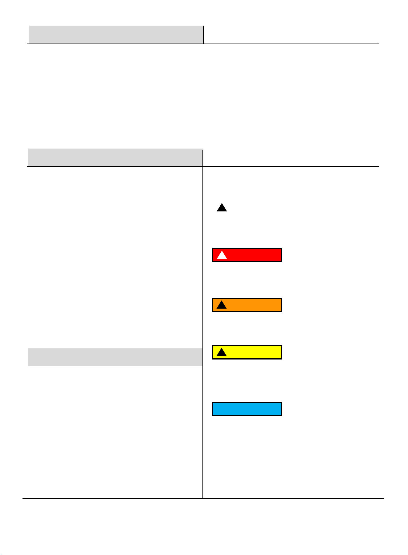
DANGER
!
DANGER indicates an imminently hazardous
situation which, if not avoided, will result in death
or serious injury.
WARNING
!
WARNING indicates a potentially hazardous
situation which, if not avoided, could result in
death or serious injury.
CAUTION
!
CAUTION indicates a potentially hazardous situation
which, if not avoided, may result in minor or moderate
injury. It may also be used to alert against unsafe
practices.
NOTICE
Failure to follow the instruction may result in the
damage to your generator and other property.
Safety Warnings and Notices
WARNING: Save This Manual
for Future Reference
This manual contains important information regarding
the safety, operation, maintenance, and storage of this
product. Before use, you must read and fully
understand all cautions, warnings, instructions, and
product labels. Failure to do so could result in serious
personal injury and/or property damage.
Safety Definitions
!
This safety alert symbol appears with most safety
statements. It means to pay attention and be alert, your
safety is involved! Please read and abide by the
message that follows the safety alerts symbol.
2
Safety Instructions
Follow all safety information provided in this manual and
on the generator.
Before operating the generator, you must read and
understand this manual fully and familiarize yourself with
safe operating practices.
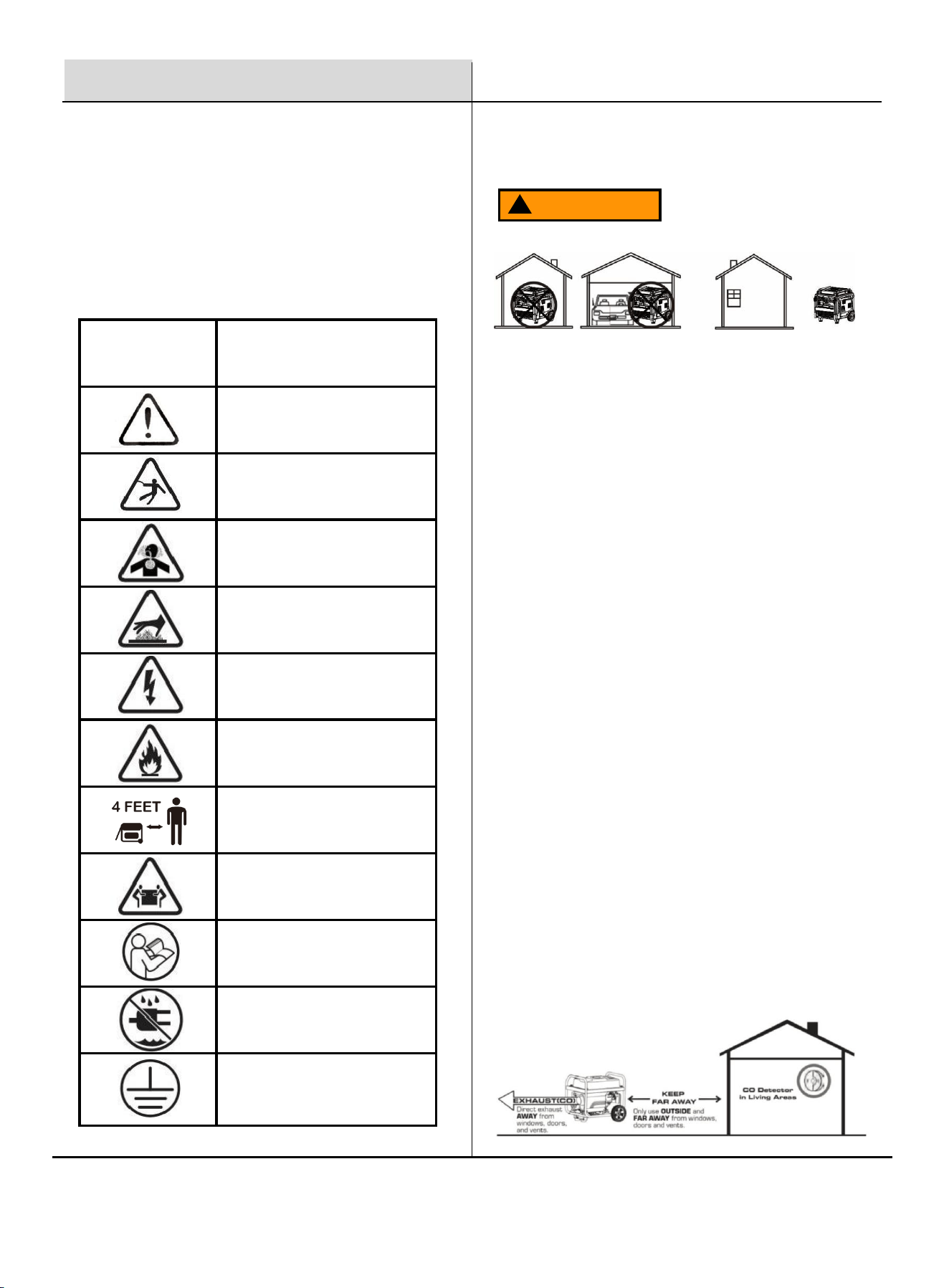
SYMBOL
DESCRIPTION
Safety Alert Symbol
Electrocution Hazard
Asphyxiation Hazard
Burn Hazard. DO NOT touch hot
surfaces.
Electrical Shock Hazard
Fire Hazard
Maintain Safe Distance
Lifting Hazard
Read Manufacturer's Instructions
DO NOT Operate in Wet Conditions
Grounding. Consult a qualified
electrician to determine the
necessary grounding requirements
before operating this product.
Safety Precautions
Operate this product ONLY outdoors, far away from
windows, doors, and vents, to reduce the risk of carbon
monoxide gas buildup, which could accumulate and be
drawn into occupied spaces.
DO NOT operate this product under the influence of
alcohol, while exhausted or sleep-deprived, when
drowsy from medications, or under any condition that
could impair your judgment or prevent safe operation.
Avoid operating this product under the following
circumstances:
1. When the ground is slippery or when other conditions
exist which might make it not possible to maintain a steady
posture.
2. At night, at times of heavy fog, or at any other times when
your field of vision might be limited, it would be difficult to
gain a clear view of the area.
3. During rainstorms, during lightning storms, at times of
strong or gale-force winds, or at any other times when
weather conditions might make it unsafe to use this product.
POISONOUS GAS HAZARD: Engine exhaust contains
carbon monoxide, a poisonous gas that could kill you in
minutes. You CAN NOT smell it, see it, or taste it. Even if
you do not smell exhaust fumes, you could still be exposed
to carbon monoxide gas.
Safety Symbols
WARNING
!
3
Safety Instructions
WARNING
!
Never store fuel cans or refill the fuel tank in areas
with boilers, stoves, wood fires, electrical sparks,
welding sparks, or any other sources of heat or fire
that could ignite the fuel.
Smoking while operating the generator or refilling its
fuel tank is extremely dangerous. Never smoke or
vape while working with your generator.
When refilling the fuel tank, always turn off the engine
first. Carefully inspect the area to ensure there are no
sparks or open flames nearby before refueling. lf any
fuel spills occur during refueling, use a dry rag to
clean up the spills before restarting the engine.
After refueling, securely screw the fuel cap back onto
the tank and move the generator at least 3 meters (10
feet) away from the refueling area before restarting
the engine.
Additionally, be aware that starter cord kickback
(rapid retraction) can pull your hand and arm toward
the engine faster than you can release it, potentially
causing broken bones, fractures, bruises, sprains, or
other serious injuries. To prevent this, always pull the
recoil handle until resistance is felt,(compression
stroke),let it retract, and them pull it again swiftly and
flly.
WARNING
!
Turn the generator engine OFF and let it cool for at
least 2 minutes before removing the fuel cap.
Loosen the cap slowly to relieve pressure in the tank.
⚫ Fill or drain fuel tank outdoors.
⚫ DO NOT overfill the tank. Allow space for fuel
expansion.
⚫ If fuel spills, wipe it up and let the area dry before
starting the engine.
⚫ Keep fuel away from sparks, open flames, heat, and
other ignition sources.
⚫ Check fuel lines, tank, cap, and fittings frequently for
cracks or leaks; replace them if necessary.
⚫ DO NOT smoke or vape anything.
Fuel and its vapors are extremely flammable and
explosive which could cause burns, fire, or
explosion resulting in death or serious injury and/or
property damage.
When Adding or Draining Gasoline
Before starting your generator, you must read and
understand the manual and familiarize yourself with safe
operating practices. Improper treatment of the generator
could damage it and shorten its lifespan.
Keep the handles dry, clean, and free of oil or fuel residue.
Before Starting the Generator
⚫ Never operate this product in enclosed or partially
enclosed spaces, including homes, garages, sheds,
basements, or crawlspaces, even if using fans or
open windows and doors for ventilation. Carbon
monoxide can build up quickly and linger for hours,
even after the engine is off.
⚫ Install battery-operated or plug-in carbon
monoxide alarms with battery backup as per the
manufacturer's instructions. Most smoke alarms do
not detect carbon monoxide.
⚫ Position the product downwind and direct the
exhaust away from occupied spaces. If you
experience symptoms like dizziness, weakness, or
nausea, immediately turn off the product, move to
fresh air, and seek medical attention, as these may
indicate carbon monoxide poisoning.
4
Components
When Starting the Unit
Ensure the spark plug, muffler, fuel cap, and air
cleaner are properly in place.
DO NOT crank the engine with the spark plug removed.
Safety Instructions
WARNING
!
Never touch the muffler, spark plug, or other metal
parts of the inverter generator while it is running or
immediately after stopping. Doing so could result in
serious burns or electrical shock.
NOTICE
⚫ Use the generator only for its intended
applications.
⚫ Operate the generator only on solid, level
surfaces.
⚫ DO NOT insert any objects through the cooling
slots.
⚫ DO NOT expose the generator to excessive
moisture, dust, dirt, or corrosive vapors.
⚫ If connected devices overheat, turn them off and
disconnect them from the generator immediately.
Shut off the generator if:
⚫ Electrical output is lost.
⚫ Equipment sparks, smokes, or emits flames.
⚫ The unit vibrates excessively.
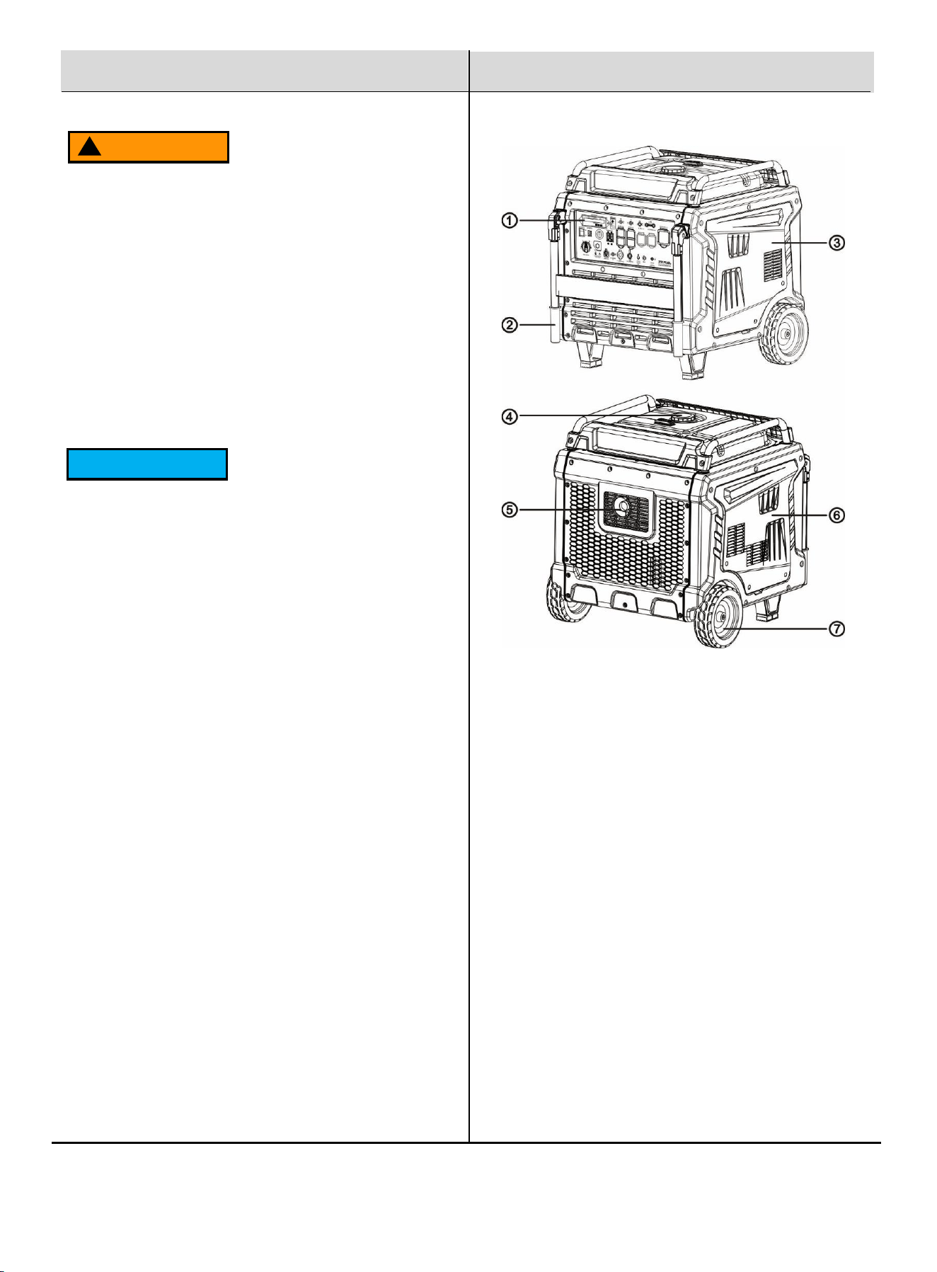
1. Control Panel: Contains the electrical outlets and operational
controls for the generator.
2. Transport Handle: Facilitates easy transport of the generator.
3. Right Side Cover
4. Fuel Tank Cap: Use this cap to add gasoline to the generator.
5. Muffler and Spark Arrestor: The spark arrestor prevents
sparks from exiting the muffler, enhancing safety.
6. Left Side Cover
7. Wheel (x2): Facilitating the movement of the generator.
5
Control Panel
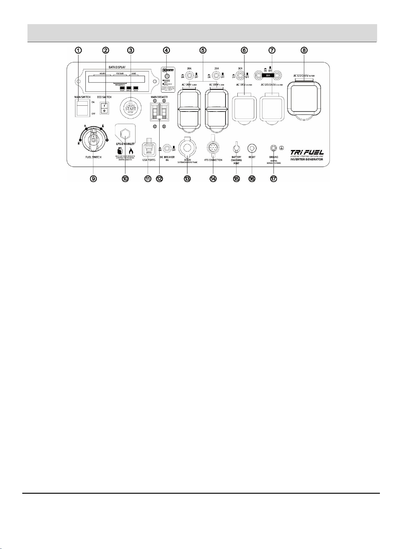
1. Main Switch: Manage battery power and shutdown. Tip: If you do not use the generator for more than 7 days (168 hours),
please press the main switch to the "OFF" position, which can prevent the battery from running out.
2. ECO Switch: Minimizes engine speed, noise, and fuel consumption under light electrical load.
3. Electric Start Button (One-Push Start): Press this button, start or stop the engine.
4. CO Indicator: Detects the presence of carbon monoxide and may shut down the unit automatically for safety.
5. 120 Volt AC, 20 Amp Duplex NEMA 5-20R Receptacle: This receptacle is rated for a maximum of 20 amps
6. 120/240V AC, 30 Amp L5-30R Outlet: The outlet can carry a maximum of 30 amps.
7. 120/240V AC, 30 Amp L14-30R Outlet: The outlet can carry a maximum of 30 amps.
8. 120/240V AC, 50Amp 14-50R Outlet: The outlet can carry a maximum of 50 amps.
9. Fuel Switch: GAS/LPG/NG valve that changes the fuel into the engine.
10. LPG/NG Inlet: When LPG/NG gas is used, install the dedicated LPG/NG hose on the connection port.
11. USB Ports: 5V DC output with one USB-A port and one USB-C port
12. Main Breaker: The main circuit breaker controls total output of all outlets to protect the generator from
overload or short circuit.
13. DC Cigarette Lighter Outlet: 12V DC 8.3A.
14. ATS: A dedicated connector that allows the generator to work with an automatic transfer switch, enabling the generator to
automatically start and supply power during a utility outage.
15. Battery Charging Port: Use battery charger to charge the generator battery. (After connecting the battery, the generator will
automatically recharge it during operation.)
16. Reset: If the generator is overloaded, the reset breaker will trip. The engine will continue to run, but there will be no output
from the generator. Unplug the devices and reduce the load. Push in the reset breaker to reset it.
17. Ground Terminal: The ground terminal is used to externally ground the generator.

6
Control Panel
Definition of ATS Interface
PIN 1 — Battery + Connection
Connects to the positive terminal of the generator battery.
Function:
1. Supplies DC control power to the ATS.
2. When utility AC power is present, the ATS charges
the generator battery through this pin.
PIN 2 — Ground (GND)
Connects to the generator chassis or the negative battery
terminal, serving as the common reference ground for all
signal circuits.
PIN 3 — Start/Stop Signal
Connects to the start/stop signal wire (typically blue) of the
generator’s push-button switch.
Control logic:
• To Start: When the generator is off, the ATS
connects Pin 3 and Pin 2 for 0.5 to 5 seconds,
then disconnects.
• To Stop: When the generator is running, the ATS
again connects Pin 3 and Pin 2 for 0.5 to 5
seconds, then disconnects.
• Important Note: The signal takes effect at the
moment when the connection between Pin 3 and
Pin 2 is broken, not during the connection period.
This momentary signal is used to toggle the
generator’s state based on its current status.
The generator shuts down instantly and cannot be
started again if the emergency stop switch is
not restored.
PIN 4 — Emergency Stop (Flameout Control)
Connects to the flameout wire (usually black/red) of the
generator’s ignition circuit.
Function:
• When the emergency stop is triggered, the ATS
connects Pin 4 and Pin 2, immediately cutting off
ignition.
• The generator shuts down instantly and cannot be
started again if the emergency stop switch is
not restored.
PIN 5 — Not in Use
PIN 6 — Generator Running Status Feedback
Connects to a DC 12V+ signal (e.g., a USB port, cigarette
lighter socket, or internal 12V logic output) that becomes
energized when the generator is running.
Purpose:
• The ATS uses this voltage signal to determine
whether the generator is running or stopped.
PIN 7 — Not in Use
7
Preparation
Add Engine Oil
Failure to follow this instruction may result in damage
to your generator and other property.
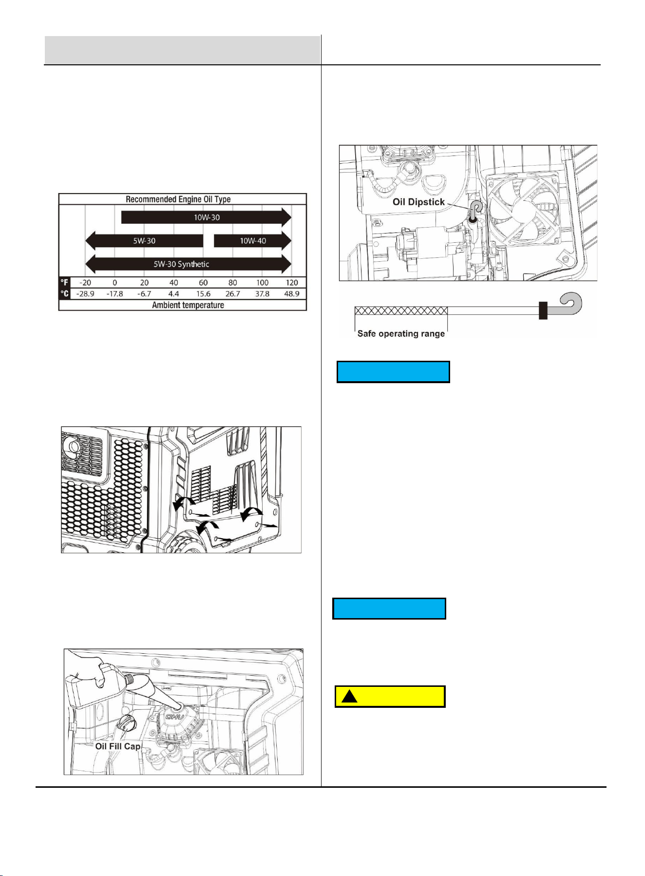
If you are operating the generator in extreme
temperatures, please refer to the following chart for
the recommended oil type.
The generator is shipped without engine oil. Do not start
the engine without ensuring it has sufficient oil.
1. Place the generator on a solid, flat, level surface.
2. On the left side of the generator, loosen the screws and
remove the maintenance cover.
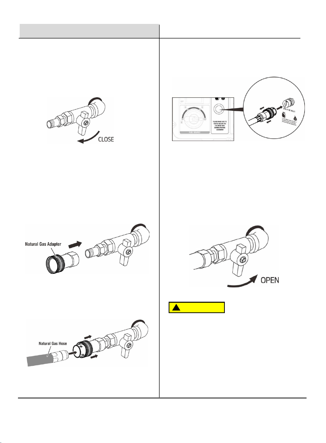
3. Remove the oil cap.
4. Using a funnel, as needed, add the appropriate type of
oil until the oil level is at the proper level. SAE 10w-30 oil
is recommended for general use. DO NOT OVERFILL.
Replace oil fill cap and secure maintenance cover.
NOTICE
Recommended Engine Oil:
⚫ Type: SAE 10W-30
⚫ Oil Grade: API Service SE type or higher
⚫ Engine Oil Capacity: 1.6 L (54.11 fl. oz)
Residual oil from the factory may remain in the
engine. Add oil slowly to prevent overfilling. Once oil
has been added, the oil level should be 1-2 threads
below the fill hole. DO NOT screw in the dipstick while
checking the oil level.
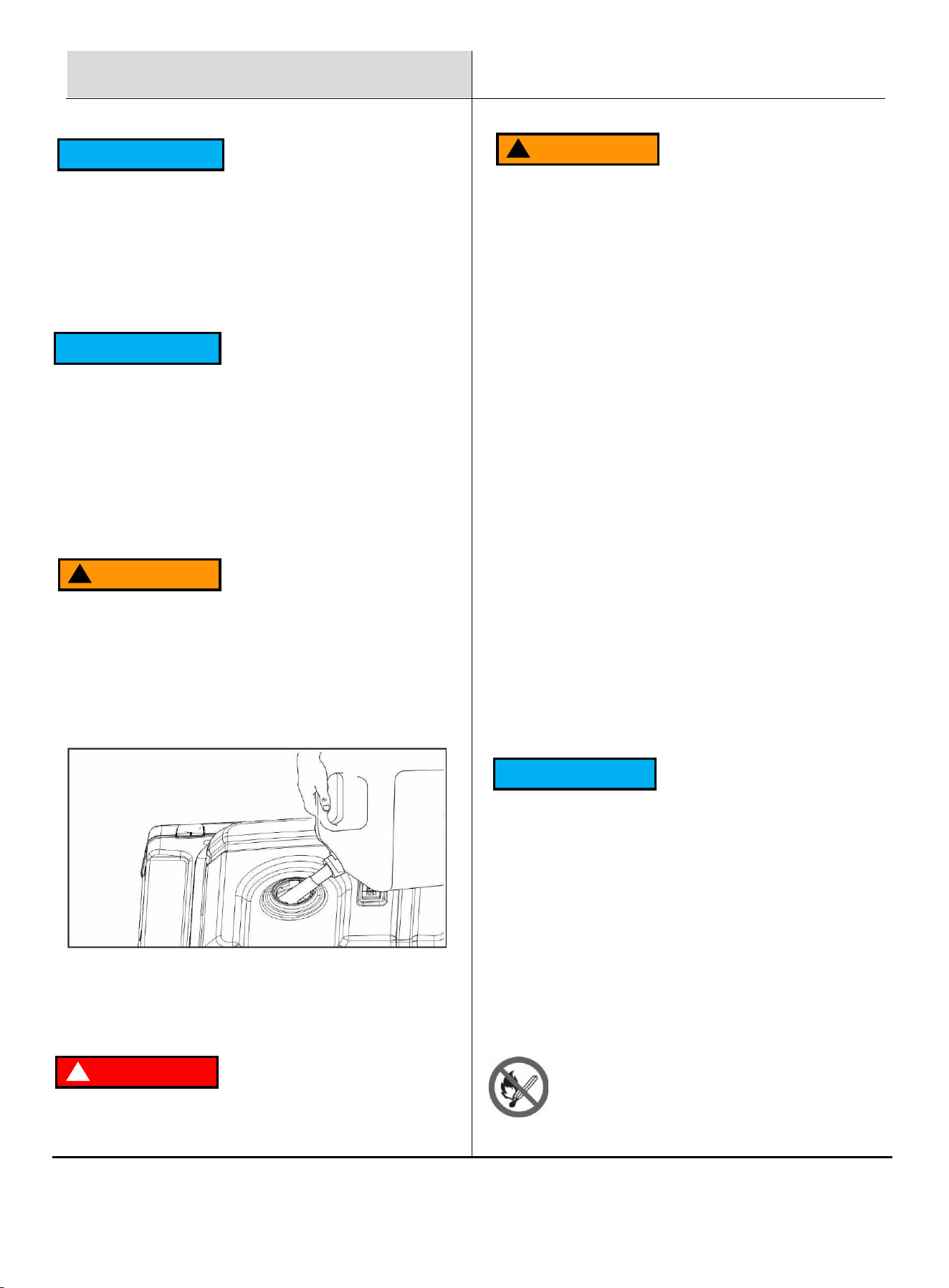
5. Check engine oil level daily and add as needed. On the
right side of the generator. Pull out the oil dipstick and
check the oil level.
NOTICE
CAUTION
!
Check oil level often during the break-in period. Refer
to the Maintenance section for recommended service
intervals.
This engine is equipped with a low oil shut-off and will
stop when the oil level in the crankcase falls below a
critical level.
8
WARNING
!
TO PREVENT SERIOUS INJURY FROM FIRE:
Fill the gasoline tank in a well-ventilated area away from ignition
sources. If the engine is hot from use, shut the engine off and
wait for it to cool before adding gasoline. Do not smoke.
Preparation
1. Make sure the generator is on a solid, flat, level surface.
2. Unscrew the fuel cap and set it aside.
3. Slowly add gasoline to the fuel tank. Be careful not to over
fill. The fuel gauge on the top of the fuel tank indicates
how much gasoline is in the generator fuel tank.
Connecting an LPG Tank
NOTICE
NOTICE
The first 5 hours of run time are the break-in period
for the unit. During the break-in period stay at or
below 50% of the running watt rating and vary the
load occasionally to allow stator windings to heat and
cool. Adjusting the load will also cause engine speed
to vary slightly and help seat piston rings. After the 5-
hour break-in period, change the oil.
Synthetic oil may be used after the 5-hour initial
break-in period. Using synthetic oil does not increase
the recommended oil change interval. Full synthetic
5W-30 oil will aid in starting in cold ambient < 41°F
(5°C) temperatures.
Add Gasoline
DANGER
!
WARNING
!
4. Replace the fuel cap and wipe up any spilled
gasoline with a dry cloth then remove the cloth from
the area.
Do not overfill the gasoline tank. Overfilling can result
in a fire, explosion, or death.
Gasoline can expand. Do not fill the gasoline tank
to the top. Leave a minimum of 1.5 inches open
space. Gasoline vapors are highly flammable. Do
not fill the tank near an open flame. Always check
for gasoline spills.
⚫ To ensure that the generator runs smoothly use
only FRESH octane 85 general gasoline.
⚫ Never use an oil/gasoline mixture. Never use old
gasoline.
⚫ Avoid getting dirt or water in the gasoline tank.
⚫ Gasoline can age in the tank and make it hard to
start up the generator in the future.
⚫ Never store generator for extended periods of time
with gasoline in the tank.
⚫ Propane tanks that use liquid withdrawal system cannot be
used on these models.
⚫ Confirm that the re-qualification date on the tank has not
expired.
⚫ DO NOT use included LPG hose for any other appliances.
NOTICE
All new propane tanks must be purged of air and
moisture prior to filling. Used propane tanks that
have not been plugged or kept closed must also be
purged. The purging process should be done by a
propane tank supplier (propane tanks from an
exchange supplier should have been purged and
filled properly).
ALWAYS position the propane tank so the
connection between the valve and the gas inlet will
not cause sharp bends or kinks in the hose.

9
Preparation
WARNING
!
Explosion hazard. DO NOT start generator if you
smell propane ALWAYS fully close the propane
tank valve and disconnect the LPG hose from the
generator when not in use.
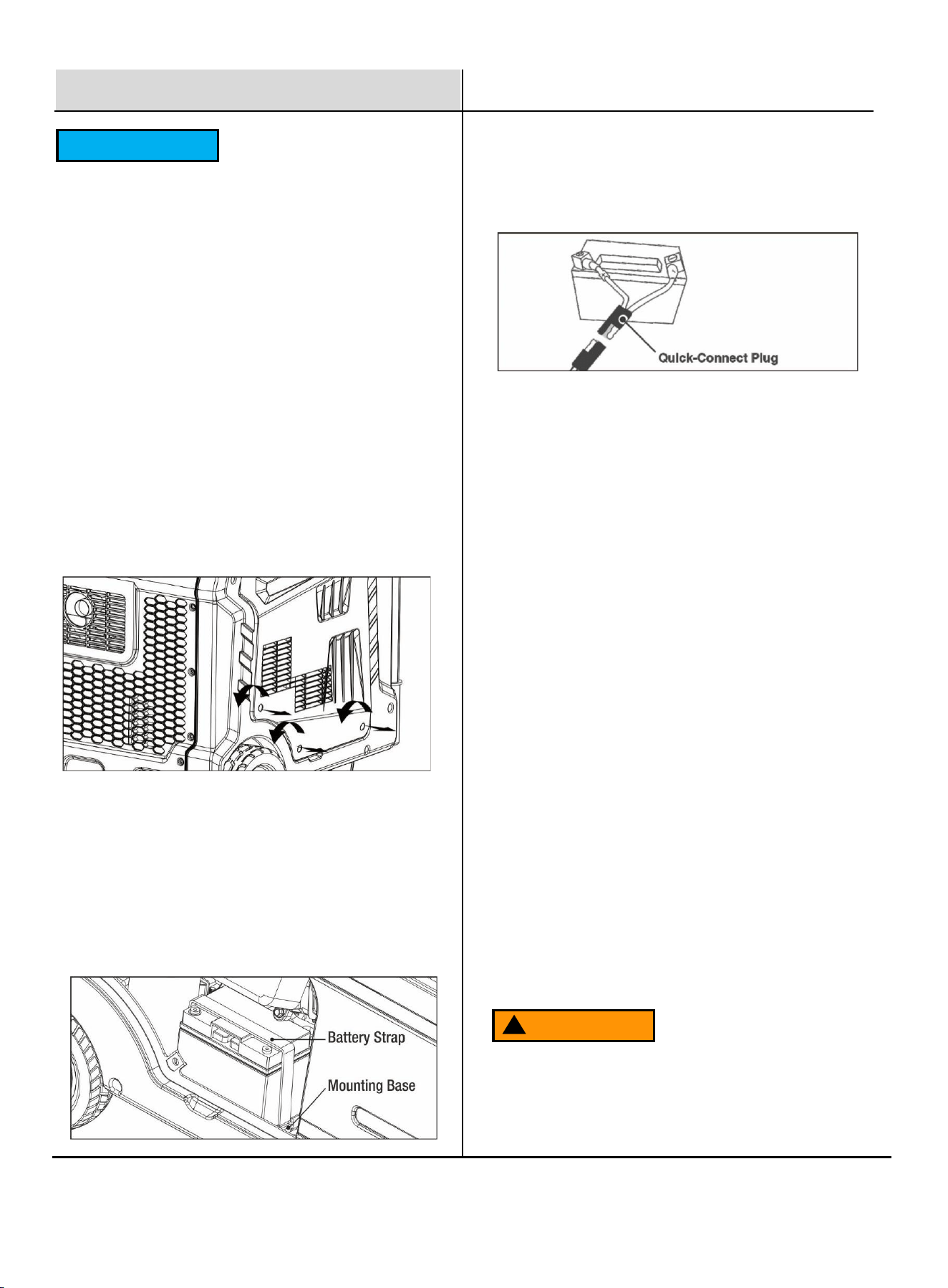
1. Turn the generator OFF and place on a flat surface
in a well-ventilated area.
2. Verify that the propane tank valve is in the fully
closed position.
3. Remove the cover on the generator propane/natural
gas inlet.
4. Tighten the LPG hose to the propane/methane inlet of
the generator.
5. IMPORTANT: DO NOT use thread seal tape or any
other type of sealant to seal the LPG hose connection.
6. Push back the quick connector collet of the LPG hose,
insert it into the generator propane/methane inlet,
loosen the quick connector sleeve, and make the
sleeve clamp the propane/methane inlet.
7. Remove the safety plug or cap from the LPG tank
valve and attach the other end of the hose to the
LPG connector on the tank. Hand-tighten.
Connect the Natural Gas (NG)
Supply Line
8. Turn the LPG tank valve to the fully open position.
Check all connections for leaks by wetting the
fittings with a solution of soap and water. Bubbles
which appear or bubbles which grow indicate that a
leak exists. If a leak exists at a fitting, turn the LPG
tank valve to the fully closed position and tighten
the fitting. Open the LPG tank valve and recheck
the fitting with the soap and water solution.
Fire and explosion hazard. Never connect or
disconnect the natural gas hose while the engine is
running. Do not smoke or create sparks while
handling natural gas. Always turn the engine off and
allow the generator to cool for at least five minutes
before connecting to natural gas.
Never use a natural gas supply line, natural gas hose,
or any other fuel item that appears to be damaged.
DANGER
!
WARNING
!
To reduce the risk of injury, perform a leak test any
time the natural gas hose is disconnected and
reconnected.
Explosion hazard. If you smell methane, do not start
the generator. Always completely close natural gas
supply line valve and disconnect natural gas (NG)
hose from generator when not in use.
NOTICE
10
Preparation
1. Turn the generator OFF, disconnect all loads, and
allow the engine to cool for at least 5 minutes before
connecting the natural gas supply.
2. Verify that the natural gas supply valve is fully
CLOSED.
6. Pull back the quick-connect collet on the natural gas
hose, insert it onto the generator’s LPG/NG inlet, and
release the collet to lock the connection. Ensure the
fitting is secure.
7. Slowly open the natural gas (NG) supply valve to
pressurize the hose. Apply a soap-and-water solution
to all fittings and connections. Bubbles that appear or
grow indicate a leak.
If a leak is detected, close the NG supply valve, tighten
the fitting, and test again.
If the leak continues or if the leak cannot be located,
DO NOT use the generator. Contact a licensed gas
professional.
3. Completely unwrap and straighten the natural gas
hose to remove twists and prevent kinks.
4. Contact your local gas company for guidance on
connecting to a natural gas supply line. Your qualified
contractor must ensure that all supply line threads are
clean, undamaged, and properly sealed. All gas pipe
connections must be made using gas-rated pipe
thread sealant or PTFE tape.
5. Pull firmly to confirm the connection is locked in place.
CAUTION
!
IMPORTANT SAFETY INFORMATION:
The natural gas adapter provided with this generator is
a hollow connector and does not function as a shut-off
valve. Your household or facility natural gas line must
be equipped with a proper shut-off valve.
Do not attempt to operate, connect, or disconnect the
natural gas hose without the supply valve fully closed.
Never check for gas leaks with an open flame. Use a
soap-and-water solution only.
11
Preparation
1. On the left side of the generator, loosen the screws
and remove the cover.
2. Verify that the rubber battery strap is firmly securing the
battery in place. If loose, pull on the strap and hook it
onto the mounting base.
Note: If the strap has slipped behind the battery, remove
the battery and secure the strap first. Reinstall the
battery, then route the strap under the battery quick-
connect cables and tighten it.
3. A quick-connect battery plug is pre-installed on the
battery. Remove the cable tie securing the plugs, align
colors, then push firmly to connect them. Ensure the
plugs are fully seated and locked together.
4. Align the tabs on the bottom of the battery access
cover with the generator case then push to reinstall
the cover.
Note: This generator includes a battery charging
feature. When the engine is running, a low charging
current will automatically recharge the battery. When
the generator is not in use, turn the Main Switch OFF
to disconnect battery power and prevent unnecessary
battery drain.
WARNING
!
Grounding The Generator
If grounding is required by local electrical code:
1. Attach a grounding wire to the grounding nut located
on the generator frame.
2. Connect the other end of the wire to a suitable
grounding rod driven into the earth to the correct
depth, per local electrical code.
3. A generally accepted grounding wire size is No. 12
AWG stranded copper wire.
Note: Grounding requirements vary by location.
Contact a licensed electrician or your local authority
to confirm grounding regulations in your area.
Failure to properly ground the generator can
result in electrocution.
Connecting The Battery
NOTICE
The gas hose has a 20.5 mm inner diameter and a 28
mm outer diameter. Natural Gas Requirement: 0.18–
0.5 PSI (5–13.8 in. WC) supply pressure with a
minimum flow of approximately 130 ft³/hr.
Connector (generator side):
Quick-Connect, NPT 3/4 (ø26 mm / 1.02 in), female,
self-sealing
Connector (hose end):
Quick-Connect, NPT 3/4 (ø26 mm / 1.02 in), male, non-
self-sealing
Adapter (included, for natural gas connection):
Quick-Connect, NPT 3/4 (ø26 mm / 1.02 in), female,
self-sealing, with dust cover
12
Operation
NEVER operate the generator inside any building,
garage, basement, crawlspace, shed, enclosure,
or the generator compartment of a recreational
vehicle.
NEVER operate or start the generator in the back
of an SUV, car, truck bed, or any other location
that can trap exhaust or restrict airflow.
DO NOT operate or store the generator in wet
conditions such as rain or snow. Using a
generator in wet conditions could result in
electric shock, serious injury, or death.
Operate the generator only in a well-ventilated
outdoor area. Maintain a minimum of 5 feet (1.5
m) of clearance from buildings, walls, vehicles,
and combustible materials.
Allow 5 feet (1.5 m) of airflow clearance on all
sides to ensure adequate cooling and service
access.
ALWAYS consider wind and air currents to
prevent exhaust from being drawn into occupied
spaces.
ALWAYS allow the generator to cool before
transporting or storing.
Failure to follow these precautions may result in
fire, personal injury, property damage, or void
your warranty.
During operation, the muffler and exhaust
components become extremely hot. If exhaust heat
is confined or cooling airflow is blocked,
temperatures may rise and create a fire hazard.
1. Make sure the generator is on a solid, flat, level
surface.
2. Disconnect all electrical loads from the generator.
Never start or stop the generator with electrical loads
connected.
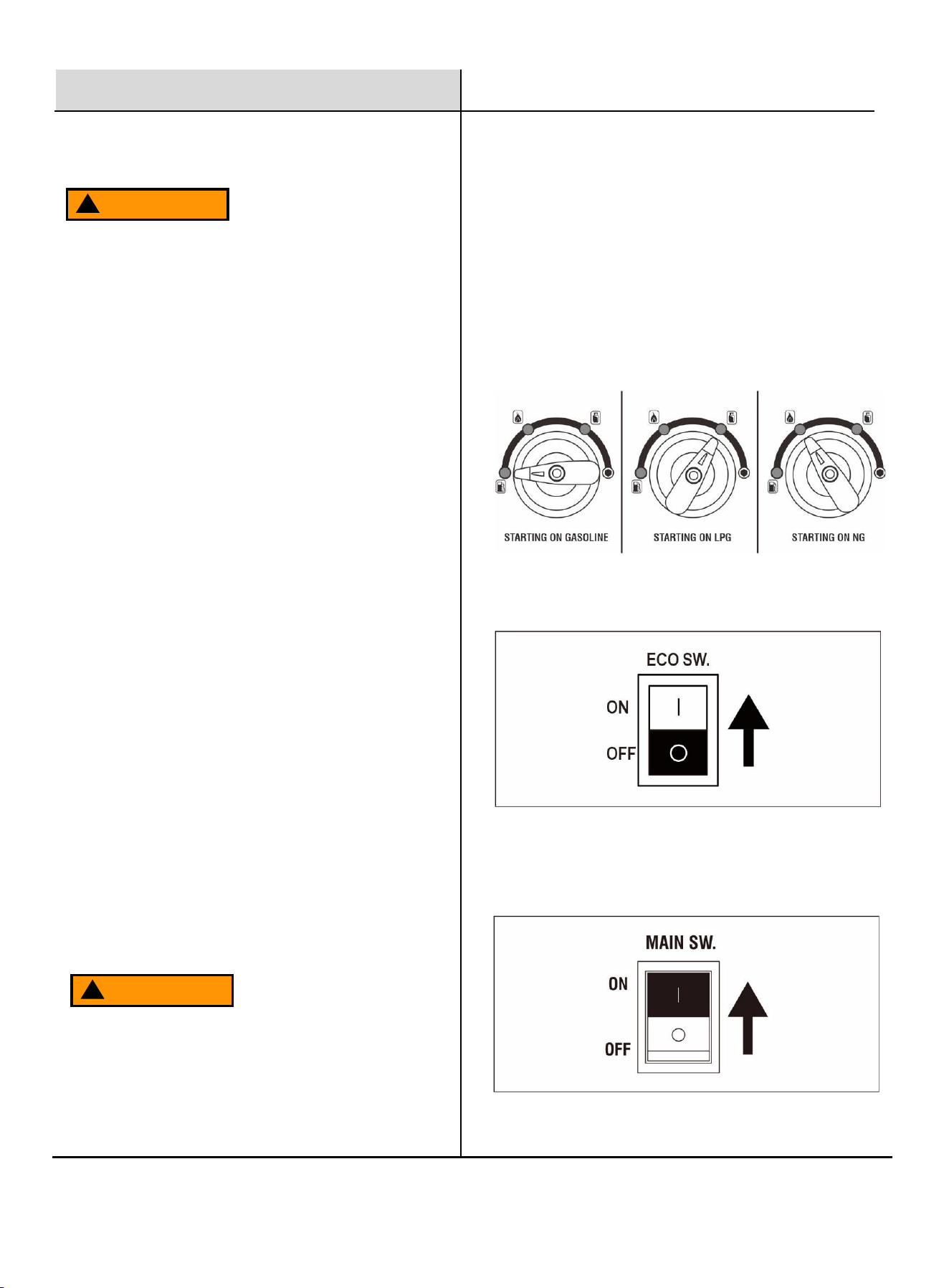
3. Turn the Fuel Switch to the desired fuel source:
• Gasoline – generator starts on gasoline
• LPG – generator starts on propane
• NG – generator starts on Natural Gas
4. ECO Switch OFF
Press the ECO Switch to the OFF position.
5. Main Switch ON
Press the Main Switch to the ON position.
WARNING
!
WARNING
!
Start The Generator
13
Operation
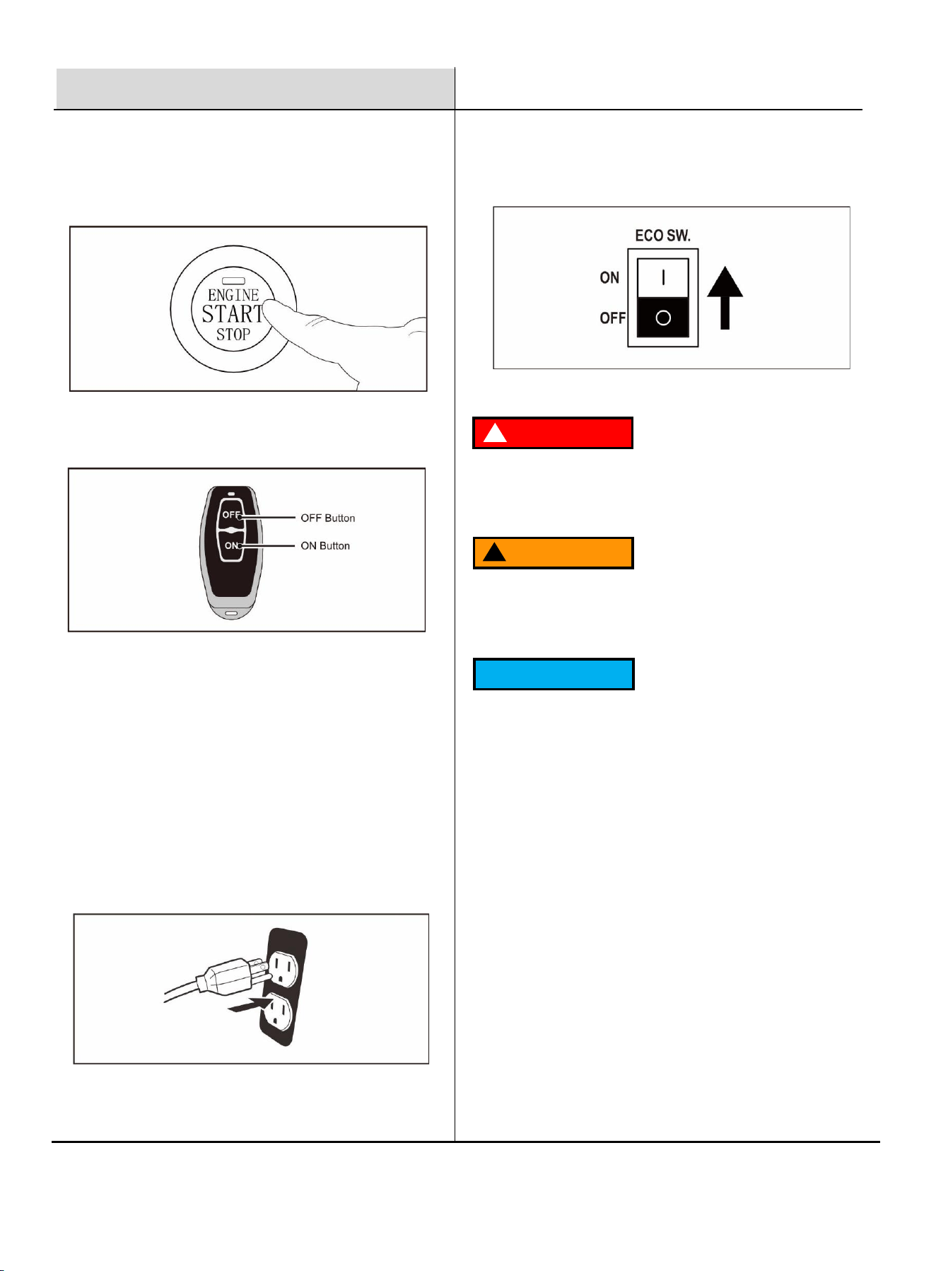
7. Choose the starting method:
One-Push Start: Press and hold the electric start
button for 0.5–5 seconds, then release. The generator
will crank automatically.
NOTE: If the generator does not successfully start
using the One-Push Start or Remote Start feature, the
battery may need to be recharged. Use recoil start to
start the generator. The battery will automatically
recharge while the engine is running.
If the generator is stored for more than 30 days,
connect a floating charger delivering 1 amp or less to
maintain the battery charge level.
DANGER
!
WARNING
!
Fire and explosion hazard. Always turn the propane
tank valve to the fully closed position if not running
the generator on propane.
When using the generator with propane, make sure
there is no possible ignition source close to the
generator.
To prevent battery drain, the remote-control receiver will
enter “sleep mode” after 120 hours of inactivity. To re-
activate remote starting, cycle the Main Power Switch
OFF and then ON again.
Gasoline to LPG/NG
IMPORTANT: Load capacity is reduced when running on
LPG or NG. Confirm that the generator can supply the
required running and surge watts before switching fuels.
Remote Start: Press the start button on the remote FOB for
1 second, then release.
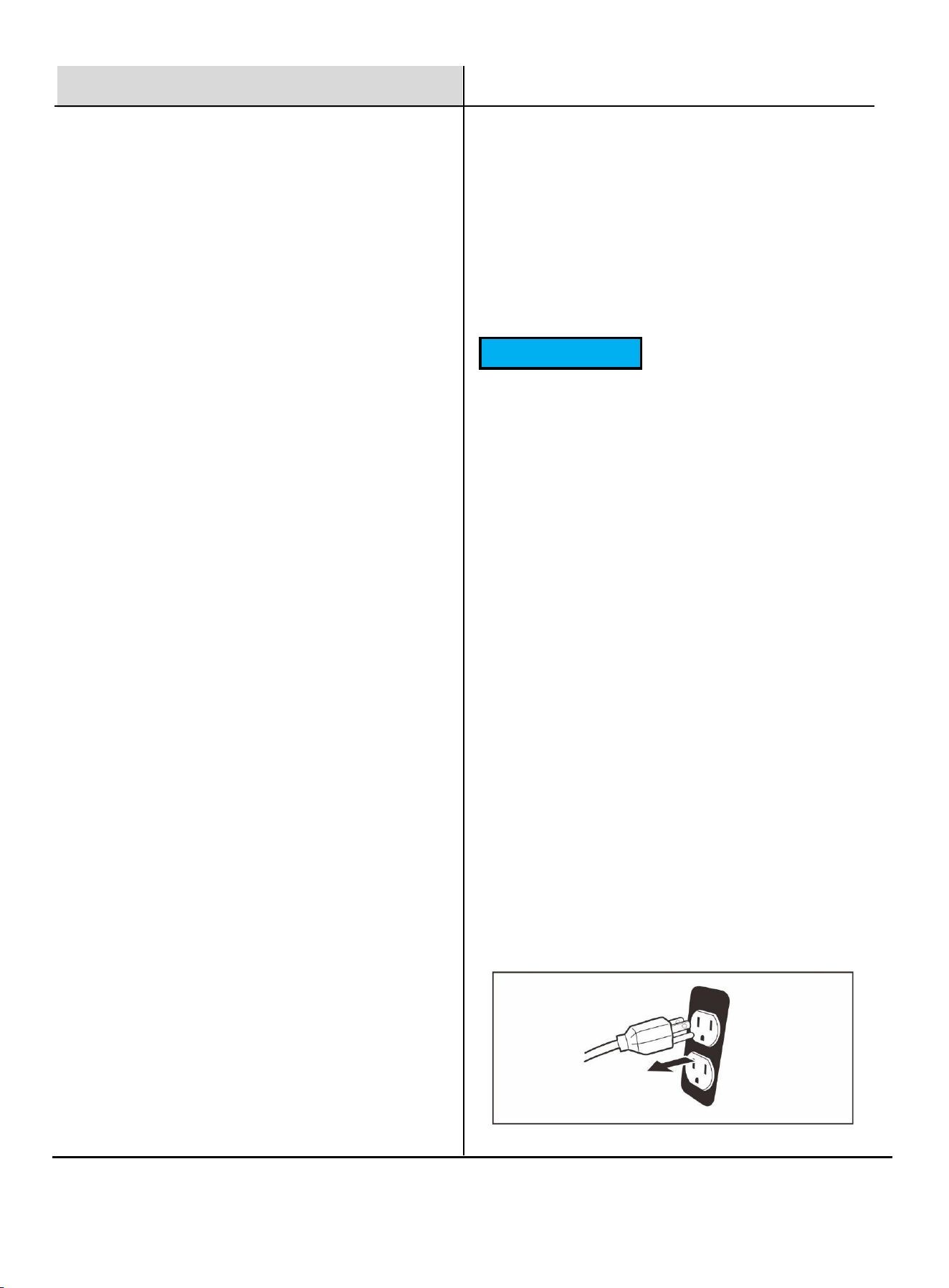
8. Plug in devices.
6. ECO Switch ON
Press the ECO Switch to the ON position.
NOTICE
1. Turn the LPG tank valve (or Natural Gas supply valve) to
the fully open position.
2. Turn the Fuel Selector Switch to the LPG/NG position.
3. Start the generator following the normal LPG or NG
starting procedure.
14
c
Operation
1. Turn the Fuel Selector Switch to the GASOLINE position.
2. Turn the LPG tank valve (or Natural Gas supply line valve)
to the fully CLOSED position.
NOTE: When switching from LPG/NG to gasoline, the
engine may run unevenly for a few seconds while
gasoline enters the carburetor. This is normal.
If the engine stops during fuel switching, disconnect all
electrical loads and restart the generator using the
selected fuel source.
IMPORTANT: Do not switch fuel sources while the
generator is under load.
LPG/NG to Gasoline
1. If the engine oil level becomes too low, the LOW OIL
light will turn on, and the engine will automatically shut off.
2. The engine cannot be restarted until the correct amount
of oil has been added. Fill with the appropriate type and
viscosity of engine oil until the oil level reaches the proper
mark.
Recommended oil: SAE 10W-30
Stop The Engine
1. Turn off and unplug all connected electrical loads.
Never start or stop the generator with electrical devices
plugged in or turned on.
The parallel connection ports allow you to connect
two generators to increase total available power.
Use only a Pulsar-approved parallel kit and follow the
instructions included with the kit for proper
installation and operation.
Parallel Operation
NOTE: The OVERLOAD light may turn on for a few
seconds as a large device starts. This is normal for
loads near the generator’s capacity.
1. The total combined load connected to the generator
must not exceed its rated running wattage.
2. If the OVERLOAD light turns on and the generator
stops supplying power, the generator has been
overloaded.
3. Turn OFF and disconnect all electrical devices. Stop
the engine. Compare the wattage of connected devices
with the generator’s rating and reduce the load if
necessary.
4. Check if any circuit breakers have tripped and reset
them before restarting the generator.
5. Restart the generator and reconnect devices carefully
while ensuring the combined load does not exceed the
generator’s capacity.
6. Any generator will produce reduced power in high
altitude or high temperature conditions.
Overload Indicator
Low Oil Indicator
The Voltage Selector controls whether the generator
outputs 120V only or both 120V and 240V.
120V Position:
All 120V receptacles and the 120V/240V (dual voltage)
receptacles will output 120V only.
This allows more current to be available at 120V outlets
when 240V is not required.
120V/240V Position:
Both 120V and 240V receptacles can be used.
NOTE:
• Do not change the Voltage Selector while the
generator is under load.
• For parallel operation, the Voltage Selector must be
set to 120V/240V.
Voltage Selector
Do not attempt to run the engine with insufficient oil.
The engine will shut off automatically if the oil level is too low.
NOTICE
15
Operation
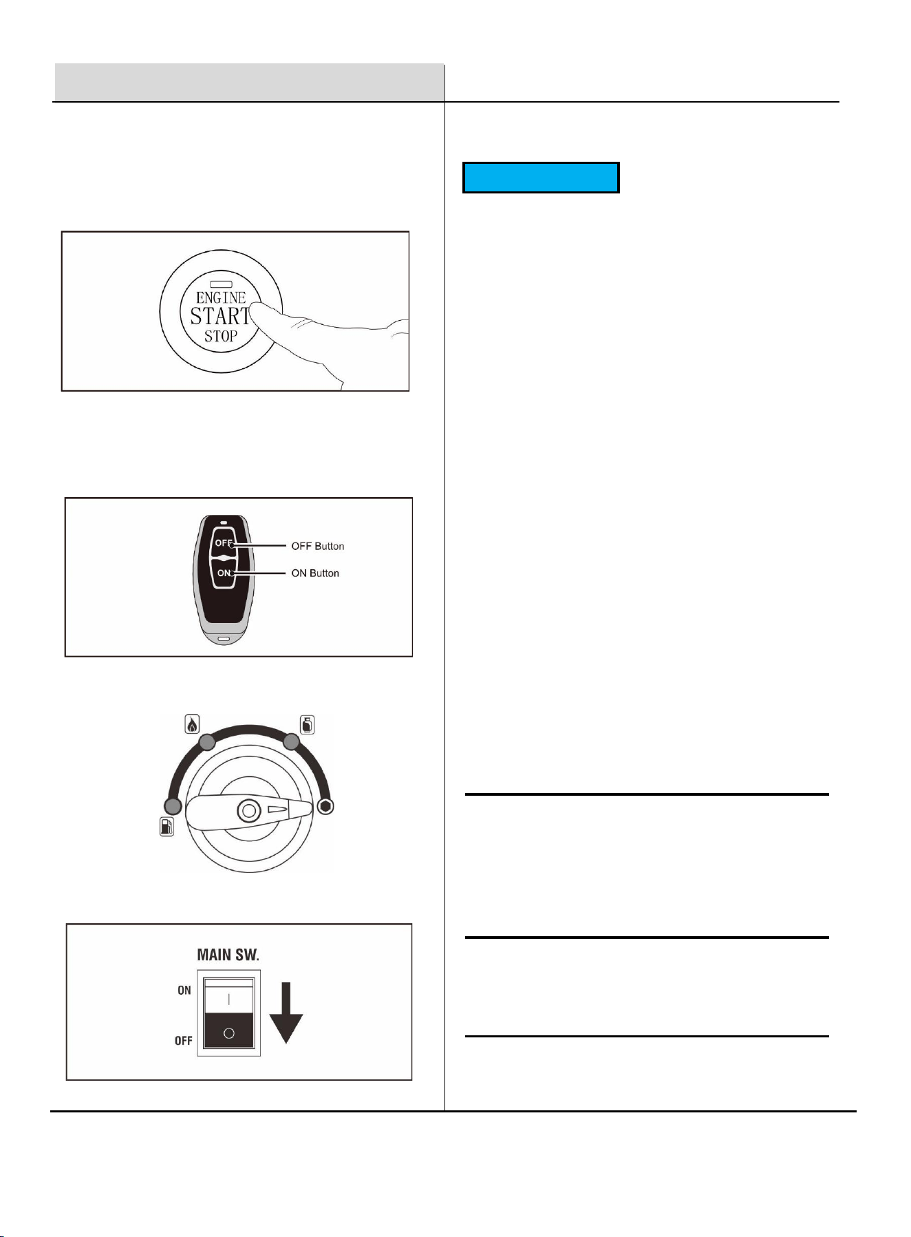
3. Turn the fuel selector knob to the off position.
NOTICE
Do not overload the generator’s capacity. Exceeding
the generator’s wattage rating may damage the
generator and/or connected electrical devices.
Make sure the generator can supply enough
continuous (running) watts and surge (starting) watts
for all items you plan to power at the same time.
The total power requirements (Volts × Amps = Watts)
of all connected devices must be considered. Most
appliances and power tools list their wattage on a
label near the model or serial number.
To determine the required generator capacity:
1. Select the items you will power at the same time.
2. Total the continuous (running) wattage of these
items. This is the amount of power the generator
must produce to keep them operating.
3. Estimate how many surge (starting) watts you will
need. Surge watts are the short bursts of extra
power needed to start motors and compressors (for
example: refrigerators, air conditioners, power tools).
Only the highest surge wattage is added to the total
from Step 2.
Generator Capacity
2. Select a Stopping Method
One-Push Stop: Press the electric start button on the
generator control panel 0.5-5 seconds to shut down the
generator.
4. Main Switch down to OFF position.
Tool or Appliance
Running
Watts*
RV Air Conditioner (13,000 BTU)
TV (Flat Screen)
RV Refrigerator
Radio
Light (75 Watts)
Coffee Maker
1100
150
180
50
75
600
2155 Total
Running
Watts*
Starting
Watts*
1800
150
600
50
75
600
3275
Highest
Starting
Watts*
*Wattages listed are approximate. Verify actual wattage.
Example:
Remote Stop:
Press and hold the off button on the remote key fob for 1
second, then release to stop the generator.

16
Maintenance
WARNING
!
ACCIDENTAL STARTING: Turn the Fuel Selector to the OFF position, allow the engine to cool, and disconnect the
spark plug wire before performing any inspection, maintenance, or cleaning.
EQUIPMENT FAILURE: Do not operate a damaged generator. If abnormal noise, vibration, or excessive exhaust
smoke is noticed, stop using the generator and have it inspected by a qualified technician.
Many maintenance procedures, including those not described in this manual, must be performed by a qualified
technician. If you are unsure of your ability to safely service the equipment, have a qualified technician perform the
work instead.
Maintenance Schedule
Cleaning, Maintenance, and Lubrication Schedule
Note: This schedule is intended as a general guide. If engine performance decreases or unusual operation occurs,
inspect the generator immediately. Actual maintenance needs will vary based on duty cycle, operating environment,
temperature, and fuel quality.
Note: The following procedures are in addition to normal operating checks and routine care.
Procedure
Before
Each Use
Monthly or
every 8 hr.
of use
Every 3 mo.
or 50 hr.
of use
Every 6 mo.
or 100 hr.
of use
Yearly or
every 300 hr.
of use
Every
2 Years
1. Brush off outside of engine
2. Check engine oil level
3. Check air filter
√
Change engine oil
√
Clean/replace air cleaner
√
1. Check and clean spark plug
2. Check and clean spark
arrestor
√
1. Check/adjust idle speed
2. Check/adjust valve clearance
3. Clean fuel tank, strainer
and carburetor
4. Clean carbon build-up from
combustion chamber
√
Replace fuel line if necessary
√
17
Maintenance
Checking and Filling Gasoline
WARNING
!
CAUTION
!
TO PREVENT SERIOUS INJURY FROM FIRE:
Fill the fuel tank outdoors in a well-ventilated area, away
from ignition sources. Shut the engine OFF and allow it to
cool before adding fuel. Do NOT smoke or allow open
flames near fuel or fuel vapors.
1. Clean the Fuel Cap and the surrounding area.
2. Unscrew and remove the Fuel Cap.
3. Remove the strainer and clean any dirt or debris,
then reinstall the strainer.
4. Fill the fuel tank to 1 inch below the fill neck with 87-
octane unleaded gasoline. If long-term storage is
expected, add a fuel stabilizer according to the
stabilizer manufacturer’s instructions.
5. Reinstall the Fuel Cap securely.
6. Wipe up any spilled fuel and allow fumes to
dissipate before starting the engine. Do not start the
engine if fuel vapors are present.
Engine Oil Change
HOT OIL CAN CAUSE BURNS.
Allow the engine to cool completely before servicing.
Disconnect the spark plug wire to prevent accidental
starting.
1. Make sure the generator is stopped and on a level
surface.
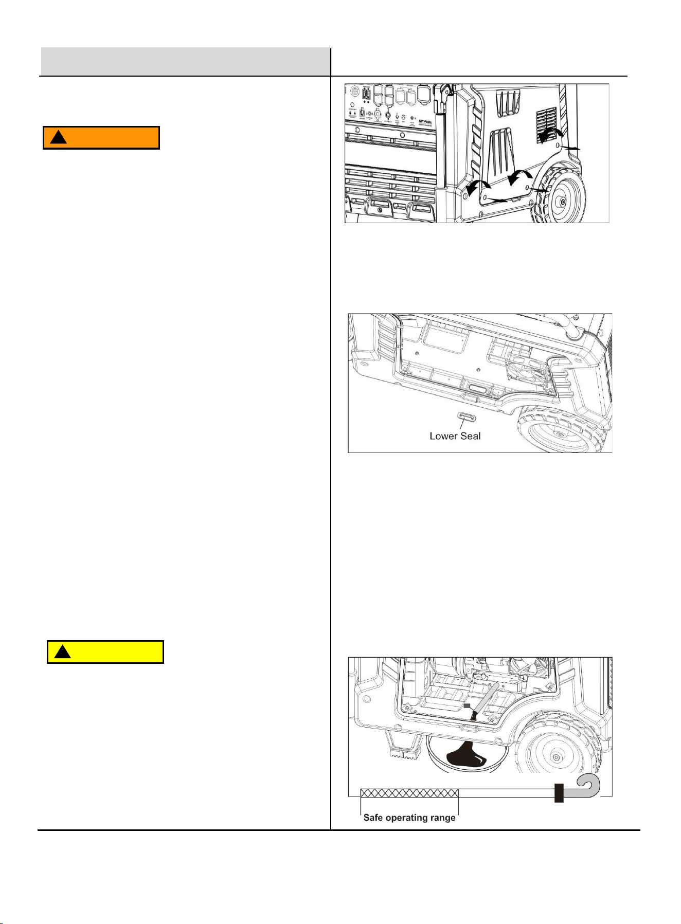
2. On the right side of the generator, loosen the side
panel screws and remove the side panel.
IMPORTANT:
Do not use gasoline containing more than 10%
ethanol (E10). Do NOT use E85.
Do not use stale gasoline or gasoline stored in a
dirty container, as contamination may cause poor
performance or engine damage.
Damage caused by improper or contaminated fuel is
NOT covered under warranty.
3. Remove the lower rubber seal from underneath the
generator.
4. Place an oil drain tray beneath the oil drain hose.
Remove the oil drain hose cap and allow oil to drain
completely. Recycle used oil properly.
5. Tighten the oil drain cap and reinstall the oil drain
hose inside the generator.
6. Clean any spilled oil from the base plate and
reinstall the rubber seal cover.
7. Add the appropriate type of engine oil until the oil
level reaches the “Safe Operating Range” on the
dipstick. Recommended oil: SAE 10W-30.
8. Do not overfill. Overfilling may cause engine
damage.
9. Install the Oil Fill Cap/Dipstick and turn clockwise
until tight. Reinstall the Oil Fill Access Door.
18
Maintenance
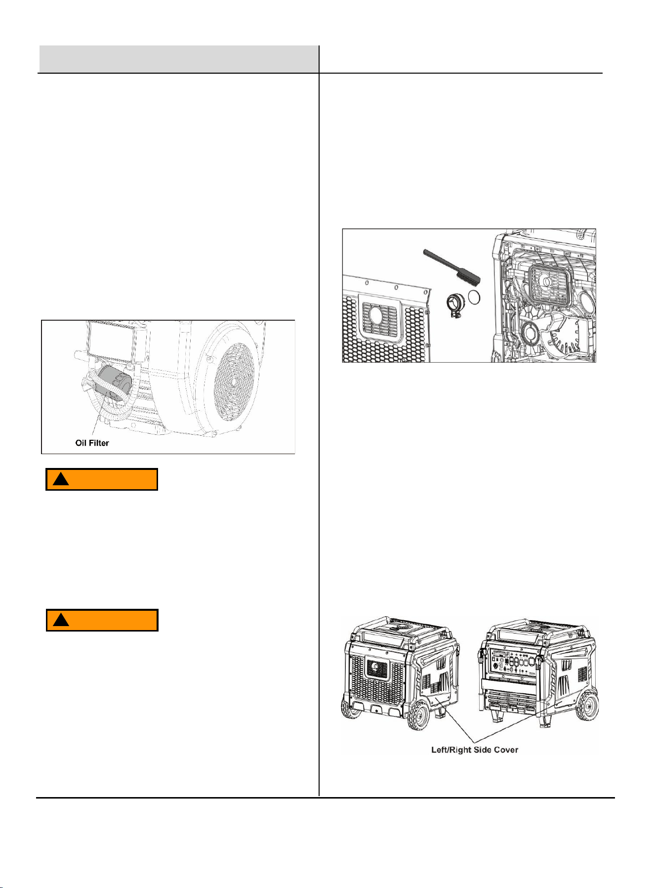
Replace Engine Oil Filter
WARNING
!
Oil filters remove impurities such as dust, metal
particles, and carbon deposits from the engine oil.
It is recommended to replace the oil filter every 250
operating hours.
1. Drain the engine oil following the procedure in the
“Engine Oil Change” section.
2. Remove the left side cover of the generator.
3. Place an oil drain container under the oil filter to
catch any spilled oil. Remove the old oil filter.
4. Install a new oil filter and tighten securely.
Always tighten the new oil filter securely. A loose oil
filter can cause oil leakage during operation, resulting
in engine damage. The new oil filter must match the
model and specifications of the original filter.
Spark Arrestor Maintenance
TO PREVENT SERIOUS INJURY AND FIRE:
Operate the generator only with a properly installed
spark arrestor. Operating without a spark arrestor
may be illegal in some areas and may violate local fire
regulations.
FIRE HAZARD:
Operating this equipment may create sparks that can
start a fire, especially near dry vegetation. A spark
arrestor may be required by law. Contact local fire
authorities or check applicable regulations for fire
prevention requirements.
To prevent serious injury or accidental brush fire, the
spark arrestor must be reinstalled securely immediately
after cleaning and before further operation.
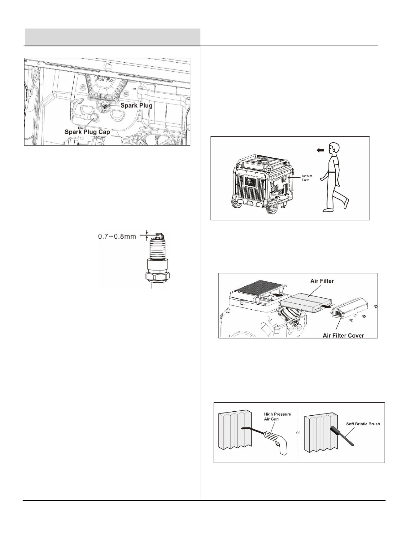
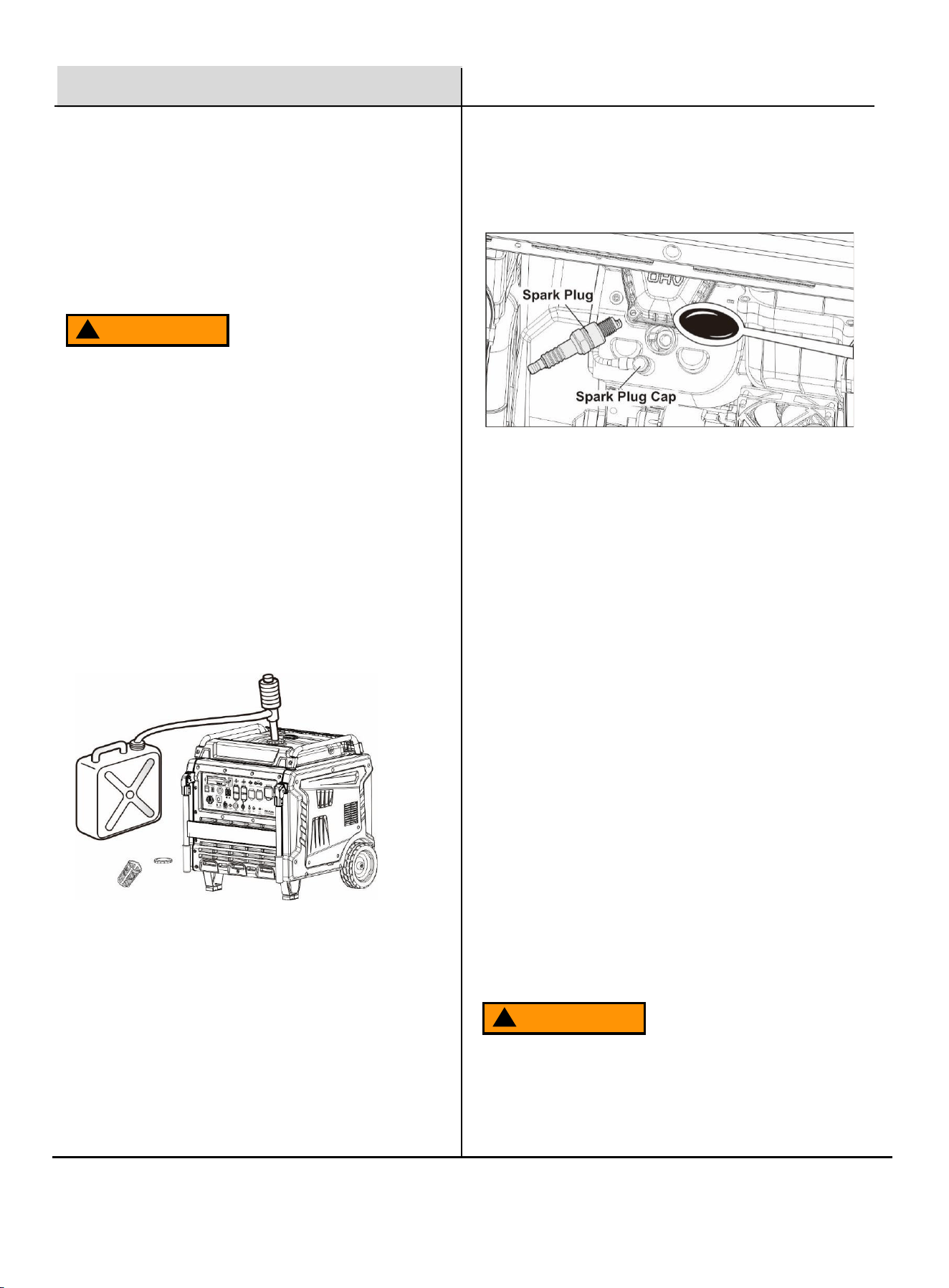
This generator uses a dual-cylinder engine, which has
two spark plugs.
Check and service both spark plugs during
maintenance.
1. Open the left side cover and the right-side cover.
2. Disconnect the Spark Plug Cap from the spark plug.
Clean away any debris from around the spark plug.
WARNING
!
Spark Plug Maintenance
To clean or replace the spark arrestor:
1. Allow the generator to cool completely.
2. Remove the screws on the back of the generator.
3. Remove the tailpipe cover and take out the spark arrestor.
4. Clean the spark arrestor using a wire brush (sold separately).
5. Replace the spark arrestor if it is damaged.
19
Maintenance
5. When installing a new spark plug, verify the gap is
correct before installation. Do not pry on the center
electrode—this can cause damage.
6. Apply a small amount of anti-seize compound to the
spark plug threads. Install the new or cleaned spark
plug into the engine by hand first to prevent cross-
threading.
7. Tighten the spark plug to 22 N·m (16 ft-lb).
⚫ If the electrode is oily, clean it with a clean, dry
cloth.
⚫ If there are carbon deposits, clean the
electrode with a brass wire brush.
⚫ If the white ceramic insulator is cracked,
chipped, or damaged, replace the spark plug.
8. Reinstall the Spark Plug Cap, then reinstall the left
and right-side covers.
Air Filter
4. Clean the air filter element using compressed air or
a soft-bristle brush.
⚫ Brush in the direction of the filter folds
⚫ Blow compressed air from the inside out
⚫ Do not wash the paper filter element with
water. Water will damage the filter.
A dirty air filter can restrict airflow to the carburetor and
cause poor engine performance or starting problems.
Inspect and clean the air filter regularly. If the generator
is operated in a dusty environment, service the air filter
more frequently.
3. Using a spark plug wrench, remove the spark plug.
4. Inspect the spark plug:
⚫ If the electrode is oily, clean it with a clean,
dry cloth.
⚫ If there are carbon deposits, clean the
electrode with a brass wire brush.
⚫ If the white ceramic insulator is cracked,
chipped, or damaged, replace the spark plug.
2. Loosen the bolts securing the air filter cover and
remove the cover.
3. Remove the air filter element.
Standard spark: NGK
Spark plug gap: 0.7-0.8mm
1. Open the left side cover.
20
Do NOT start the engine before the air cleaner is
properly installed.
Operating without the air cleaner can allow dust to
enter the engine, causing excessive wear or serious
damage.
Maintenance
Generator Storage
3. Pull the recoil starter handle gently until resistance is
felt. This closes the intake and exhaust valves.
4. Store the generator in a clean, dry location.
If the generator will be stored for an extended period,
follow the steps below to prevent fuel and engine
deterioration:
1. Turn OFF the generator.
2. Remove the fuel cap and take out the fuel filter
screen. Pump or drain all gasoline from the fuel tank
into an approved storage container. Reinstall the
filter screen and fuel cap.
WARNING
!
Generator Transport
Ensure the fuel tank cap is tightened and no fuel is
leaking.
• Do NOT overfill the fuel tank.
• Do NOT run the generator during transport.
• Avoid direct sunlight and high temperatures during
transport.
• Avoid transporting on rough or uneven roads for long
distances.
Run the generator for at least 10 minutes every 3
months to maintain lubrication and battery charge.
WARNING
!
Preparation for Use After Storage
1. Slowly pull the recoil starter handle several times to
remove excess oil from the cylinder.
2. Remove the spark plug, wipe off excess oil, and
reinstall the spark plug. Tighten securely.
3. Reconnect the spark plug cap.
4. Add fresh gasoline to the fuel tank.
5. Start the generator following the operating
instructions in this manual.
5. Install the foam filter element inside the air filter
housing.
Tip: Make sure the foam element is seated properly
and no air gaps are present.
6. Reinstall the air filter cover and tighten the screws
securely.
7. Reinstall the side cover.
5. Start the engine and let it run until it stops. This
removes gasoline from the carburetor.
6. Tip: Do not connect any electrical loads during this
process. Run time will vary depending on the
remaining fuel in the fuel system.
7. Remove the oil fill cap/dipstick and drain engine oil
completely. Refill with fresh oil to the proper level,
then reinstall the oil fill cap/dipstick.

21
Specifications
Product Description
17,000W Tri-Fuel Inverter Generator
Engine Type
V-Twin, 4-stroke, air-cooled, OHV
Displacement
760 cc
Cooling System
Forced-air cooling
Start Type
Electric Start (One-Push) / Remote Start
Fuel Type
Gasoline, Propane (LPG), Natural Gas (NG)
Fuel Tank Capacity
10.6 US gal (40 L)
Engine Oil Capacity
54.11 fl oz (1.6 L)
Engine Oil Type
SAE 10W-30, API SE or higher
Noise Level (7 m @ 50% load)
66 dB
Natural Gas Requirement
0.18–0.5 PSI (5–13.8 in. WC), ≥130 ft³/hr.
Rated Power
14,500 W (Gas) / 13,000 W (LPG) / 11,600 W (NG)
Peak Power
17,000 W (Gas) / 15,300 W (LPG) / 13,600 W (NG)
Rated Voltage
120V / 240V
Amperage (120V Rated/Peak)
120.8A / 141.7A (Gas)
Amperage (240V Rated/Peak)
60.4A / 70.8A (Gas)
Rated Frequency
60 Hz
Power Factor
1.0
Total Harmonic Distortion (%)
<3%
DC Output
USB 5V / 3A
Generator Type
Permanent-magnet alternator, inverter-regulated
Dimensions (L×W×H)
31.3 in × 33.3 in × 33.5 in (795 × 846 × 851 mm)
Net Weight
313 lb. (142 kg)
Warranty
3 Years

22
Troubleshooting Guide
Problem
Possible Causes
Probable Solutions
Engine will not start
Fuel Related:
1. Fuel tank empty or fuel valve closed.
2. Choke not set to START position for
a cold engine.
3. Gasoline with more than 10%
ethanol used (E15, E20, E85, etc.).
4. Old, stale, or contaminated gasoline.
5. Carburetor not primed.
6. Dirty fuel passages.
7. Carburetor float/needle stuck (fuel
odor present).
8. Excessive fuel in combustion
chamber due to stuck float.
9. Clogged fuel filter.
Fuel Related:
1. Fill fuel tank with fresh 87-octane,
stabilizer-treated unleaded gasoline and
open fuel valve. Do NOT use gasoline with
more than 10% ethanol (E15, E20, E85).
2. Move Choke to START position.
3. Drain and replace ethanol-contaminated
fuel. Replace damaged components if
necessary.
4. Use only fresh 87-octane, stabilizer-
treated gasoline.
5. Press Starter Handle to prime (if
equipped).
6. Clean fuel passages. Heavy deposits
may require service.
7. Gently tap carburetor float bowl to free
stuck float.
8. Shut off fuel valve and move generator
outdoors. Contact authorized Pulsar
service center before restarting.
9. Replace fuel filter.
Ignition / Spark Related:
1. Power switch OFF.
2. Spark plug wire not connected
securely.
3. Spark plug electrode wet or dirty.
4. Incorrect spark plug gap.
5. Spark plug damaged.
6. Circuit breaker tripped.
7. Faulty ignition coil or ignition module.
Ignition / Spark Related:
1. Turn power switch ON.
2. Reconnect spark plug wire securely.
3. Remove and clean spark plug.
4. Check and correct spark plug gap.
5. Replace spark plug.
6. Reset circuit breaker and check
connected load.
7. Have qualified technician diagnose
ignition system.

23
Troubleshooting Guide
Problem
Possible Causes
Probable Solutions
The engine will not start
Compression Related:
1. Cylinder not lubricated after
long storage.
2. Loose or damaged spark
plug (hissing sound during
starting).
3. Loose cylinder head or
damaged head gasket (hissing
sound during starting).
4. Valves or tappets
misadjusted or stuck.
Compression Related:
1. Pour 1 tablespoon of engine oil into the
spark plug hole. Pull the recoil starter a
few times, then try starting again.
2. Tighten or replace spark plug.
3. Have a qualified technician inspect the
cylinder head or head gasket.
4. Have a qualified technician adjust or
repair valves/tappets.
Engine Oil Related:
1. Low engine oil.
2. Generator operating on an
incline causing low-oil
shutdown.
Engine Oil Related:
1. Fill engine oil to proper level. Always
check oil before EVERY start.
2. Operate the generator on a level
surface.
Spark Arrestor Related:
1. Spark arrestor clogged with
soot.
Spark Arrestor Related:
1. Clean or replace spark arrestor.
Engine misfires / runs rough
1. Loose spark plug cap.
2. Incorrect spark plug gap or
damaged plug.
3. Defective spark plug cap.
4. Old or low-quality gasoline.
5. Low compression.
1. Check spark plug cap and wire
connection.
2. Adjust spark plug gap or replace spark
plug.
3. Replace spark plug cap.
4. Use fresh 87-octane, stabilizer-treated
gasoline. Do not use gasoline with more
than 10% ethanol (E15, E20, E85).
5. Have a qualified technician diagnose
compression (see Compression Related
section).
Engine stops suddenly
1. Low-oil shutdown triggered.
1. Fill engine oil to proper level. Check oil
before EVERY use.

24
Troubleshooting Guide
Problem
Possible Causes
Probable Solutions
Engine stops suddenly
1. Fuel tank empty or filled with
contaminated/low-quality gasoline.
2. Defective fuel tank cap creating
vacuum and preventing fuel flow.
3. Faulty magneto.
4. Disconnected or improperly
connected spark plug cap.
1. Fill fuel tank with fresh 87-octane,
stabilizer-treated unleaded gasoline. Do
not use gasoline with more than 10%
ethanol (E15, E20, E85).
2. Test or replace the fuel tank cap.
3. Have a qualified technician inspect and
replace magneto if necessary.
4. Securely reconnect spark plug cap.
Engine stops under
heavy load
1. Dirty air filter.
2. Engine too cold.
1. Clean or replace air filter.
2. Allow the engine to warm up before
applying heavy load.
Engine knocks
1. Old or low-quality gasoline.
2. Generator overloaded.
3. Incorrect ignition timing, carbon
buildup, or worn engine parts.
1. Fill tank with fresh 87-octane, stabilizer-
treated unleaded gasoline. Do not use
gasoline with more than 10% ethanol.
2. Reduce load to within rated capacity.
3. Have a qualified technician adjust
ignition timing and inspect the engine.
Engine backfires
1. Contaminated or low-quality
gasoline.
2. Engine running too cold.
3. Intake valve stuck or
overheated engine.
4. Incorrect timing.
1. Use fresh, stabilizer-treated unleaded
gasoline (max 10% ethanol).
2. Use cold-weather fuel and oil additives
to prevent backfiring.
3. Have a qualified technician clean or
adjust the valve.
4. Check and correct ignition timing.
No power to connected
device
1. Device not properly plugged in.
2. Circuit breaker tripped.
3. Generator malfunction.
1. Turn off the device, unplug it, then plug it
in again and restart.
2. Reset circuit breaker, then reconnect the
device.
3. Contact an authorized Pulsar Service
Center for inspection or repair.
!
Follow all safety precautions whenever diagnosing or servicing the generator or engine.
25
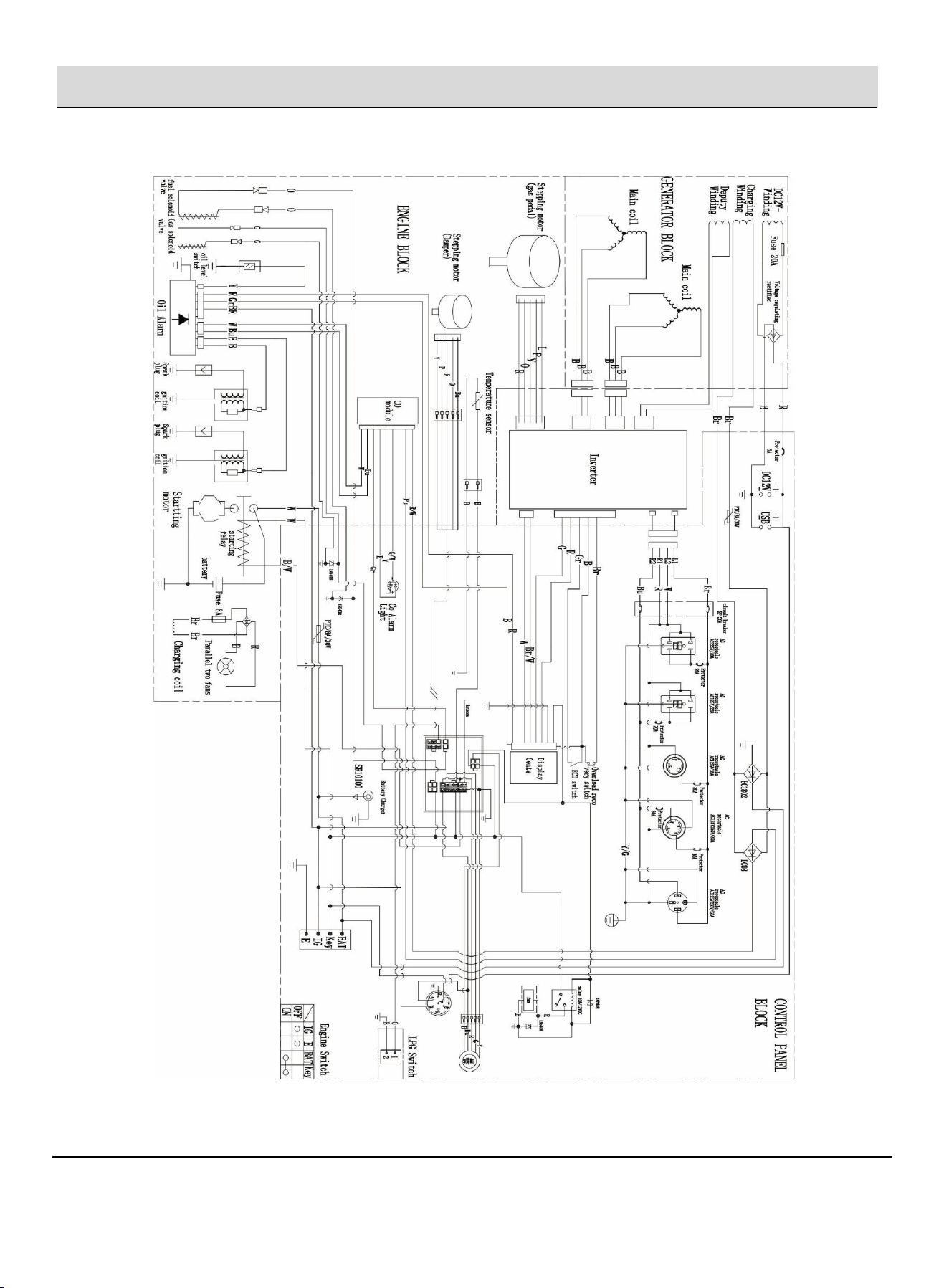
Electrical Schematic
120/240V, 60Hz Electrical
Schematic