13,000 WATT
TRI-FUEL
GENERATOR
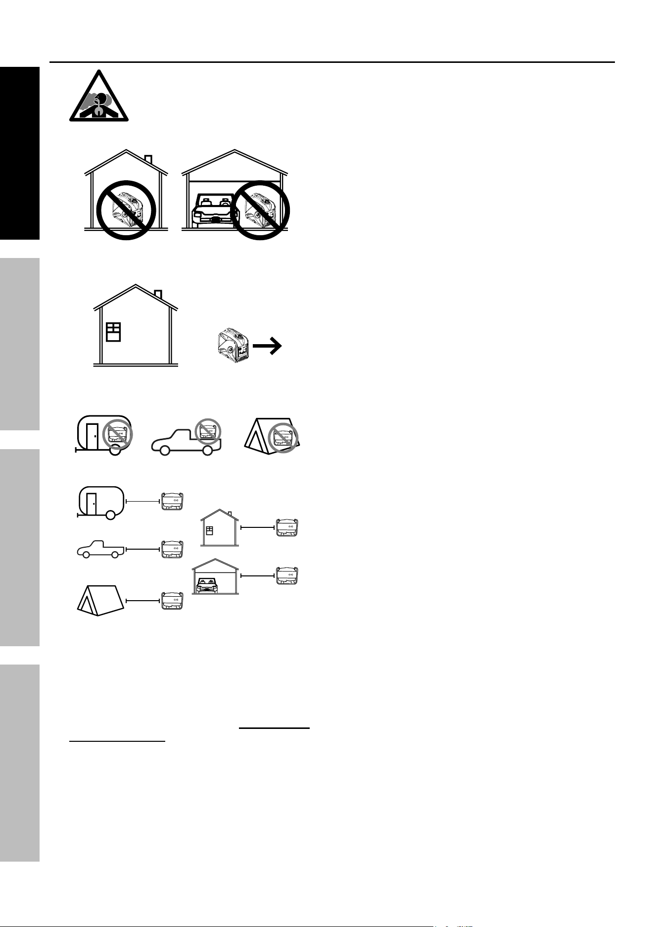
DANGER
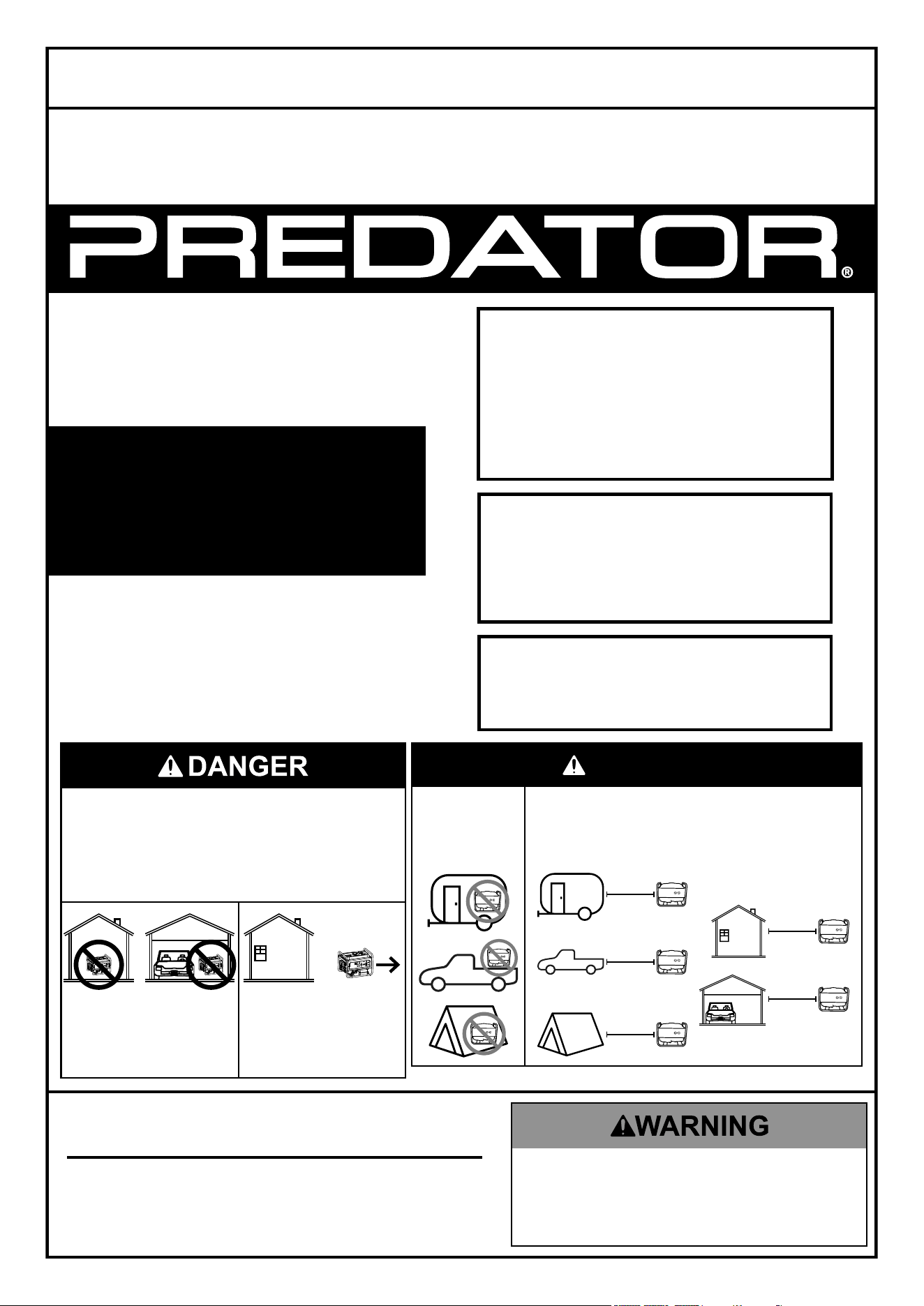
Do not use
in trailers,
truck beds,
or tents.
Use at least 20 feet away from people,
animals, and structures with exhaust pointed
away. Generator will produce carbon
monoxide when burning gas, LPG, or NG.
20′
20′
20′
20′
20′
71386
FOR YOUR SAFETY
IF YOU SMELL GAS:
1. Don’t touch electrical switches.
2. Extinguish any open flame.
3. Immediately call your gas supplier.
WARNING: Improper installation,
adjustment, alteration, service, or
maintenance can cause injury or property
damage. Refer to this manual. For
assistance or additional information consult
a qualified service technician, service
agency, manufacturer, or the gas supplier.
FOR YOUR SAFETY
Do not store gasoline or other
flammable vapors and liquids in the
vicinity of this or any other generator .
10,000 GAS RUNNING WATTS
13,000 MAX GAS STARTING WATTS
9100 LPG RUNNING WATTS
12,000 MAX LPG STARTING WATTS
7800 NG RUNNING WATTS
10,000 MAX NG STARTING WATTS
Visit our website at:
https://www.harborfreight.com
Email our technical support at:
Email our engine support at:
Owner’s Manual & Safety Instructions
Save This Manual Keep this manual for the safety warnings and precautions, assembly,
operating, inspection, maintenance and cleaning procedures. Write the product’s serial number in the
back of the manual (or month and year of purchase if product has no number). Keep this manual and the
receipt in a safe and dry place for future reference. 24j
Using a generator indoors CAN
KILL YOU IN MINUTES.
Generator exhaust contains
carbon monoxide. This is a poison
you cannot see or smell.
NEVER use inside
a home or garage,
EVEN IF doors and
windows are open.
Only use OUTSIDE
and far away from
windows, doors,
and vents.
When unpacking, make sure that the product is intact
and undamaged. If any parts are missing or broken,
please call 1-800-444-3353 as soon as possible.
Copyright
©
2024 by Harbor Freight Tools
®
. All rights reserved.
No portion of this manual or any artwork contained herein may be reproduced in
any shape or form without the express written consent of Harbor Freight Tools.
Diagrams within this manual may not be drawn proportionally. Due to continuing
improvements, actual product may differ slightly from the product described herein.
Tools required for assembly and service may not be included.
Read this material before using this product.
Failure to do so can result in serious injury.
SAVE THIS MANUAL.

Page 2
For technical questions, please call 1-800-444-3353.
71386
IF YOU SMELL GAS
1. NO FLAMES OR SPARKS!
Immediately put out all smoking
materials and other open flames.
Do not operate lights, appliances,
telephones, or cell phones.
Flames or sparks from these sources
can trigger an explosion or a fire.
2. LEAVE THE AREA IMMEDIATELY!
Get everyone out of the area where
you suspect gas is leaking.
3. SHUT OFF THE GAS. Turn off the
main gas supply valve on your
propane tank or the shutoff valve
on the natural gas source if it is
safe to do so. To close the valve,
turn it to the right (clockwise).
4. REPORT THE LEAK. From a
neighbor’s home or other nearby
building away from the gas leak, call
your propane retailer or local gas
company right away. If you can’t reach
your propane retailer or gas company,
call 911 or your local fire department.
5. DO NOT RETURN TO THE AREA
until your propane retailer, the gas
company, emergency responder,
or qualified service technician
determines that it is safe to do so.
6. GET YOUR SYSTEM CHECKED.
Before you attempt to use your
generator your propane retailer, the
gas company, or a qualified service
technician must check your entire
system to ensure that it is leak-free.
CAN YOU SMELL IT?
Propane smells like rotten eggs, a skunk’s
spray, or a dead animal. Some people
may have difficulty smelling propane
due to their age (older people may
have a less sensitive sense of smell);
a medical condition; or the effects of
medication, alcohol, tobacco, or drugs.
ODOR LOSS. On rare occasions,
propane can lose its odor. Several
things can cause this including:
•
The presence of air, water, or rust
in a propane tank or cylinder
•
The passage of leaking
propane through the soil
Natural Gas itself is odorless and
tasteless, but a chemical is added to
give it an odor in order to help detect
leaks quickly. Natural Gas is lighter than
air and will collect in higher areas.
Since there is a possibility of odor
loss or problems with your sense
of smell, you should respond
immediately to even a faint odor
of propane or natural gas.
GAS DETECTORS
Under some circumstances, you may
not smell a propane or natural gas leak.
Propane and natural gas detectors (not
included) sound an alarm if they sense
propane or natural gas in the air. They can
provide an additional measure of security.
You should consider the purchase of
one or more detectors for your home.
GUIDELINES regarding propane
or natural gas detectors:
•
Buy only units that are listed
under the latest Underwriters
Laboratories (UL) standard.
•
Follow the manufacturer’s instructions
regarding installation and maintenance.
•
Never ignore the smell of propane
or natural gas, even if no detector
is sounding an alarm.
GENERATOR MAINTENANCE
LEAVE IT TO THE EXPERTS.
Only a qualified service technician has
the training to install, inspect, service,
maintain, and repair your generator.
Have your generator and propane or
natural gas system inspected annually.
DO NOT TRY TO MODIFY OR REPAIR
valves, regulators, connectors, controls, or
other generator and cylinder/tank parts.
Doing so creates the risk of a gas leak
that can result in property damage,
serious injury, or death.
FOR NATURAL GAS SYSTEMS, fuel
system
pipes and hoses must be
leak-free
and
of adequate size to maintain specified
supply pressure and volume flow rate
under varying generator load conditions.
CO AND YOUR SAFETY
WHAT IS CARBON MONOXIDE (CO)?
You can’t taste or smell CO, but it is
a very dangerous gas. High levels of
CO can come from engine exhaust
fumes, appliances that are not operating
correctly, or from a venting system or
chimney that becomes blocked.
CO CAN BE DEADLY! High levels of CO
can make you dizzy or sick. In extreme
cases, CO can cause brain damage
or death. Symptoms of CO poisoning
include: headache, dizziness, fatigue,
shortness of breath, and nausea.
IF YOU SUSPECT CO IS
PRESENT, ACT IMMEDIATELY!
1. If you or a family member shows
physical symptoms of CO poisoning,
get everyone out of the area and call
911 or your local fire department.
2. If it is safe to do so, turn off
any appliances you suspect
may be releasing CO.
3. If no one has symptoms, but you
suspect that CO is present, call your
propane retailer,
the gas company,
or a qualified service technician to
check CO levels and your propane
or natural gas equipment.
CO DETECTORS CAN IMPROVE
SAFETY. For an extra measure
of safety, consider installing a CO
detector (not included) listed by UL
on each level of your home.
TO HELP REDUCE THE RISK
OF CO POISONING:
•
Have a qualified service technician
check your propane appliances and
venting systems annually, preferably
before the heating season.
•
Install UL-listed CO detectors
on every level of your home.
•
Never use a gas oven or range-top
burners to provide space heating.
•
Do not use the generator indoors
or in any enclosed space or in any
other area or situation that will allow
carbon monoxide to accumulate.
•
Never use a barbecue grill
(propane or charcoal) indoors
for cooking or heating.
•
Regularly check your appliance
exhaust vents for blockage.
RUNNING OUT OF GAS
DON’T RUN OUT OF GAS.
SERIOUS SAFETY HAZARDS,
INCLUDING FIRE OR
EXPLOSION, CAN RESULT.
•
If an appliance valve or a gas line is
left open, a leak could occur when the
system is recharged with propane.
•
A LEAK CHECK IS REQUIRED.
In many states, a propane retailer or
a qualified service technician must
perform a leak check of your propane
system before turning on the gas.
Page 3
For technical questions, please call 1-800-444-3353.
71386
Table of Contents
Specifications ............................................................... 3
Safety ...........................................................................4
Setup ...........................................................................12
Operation .....................................................................18
Maintenance ................................................................ 28
Troubleshooting ........................................................... 33
Parts List and Diagram ................................................ 37
Warranties ...................................................................40
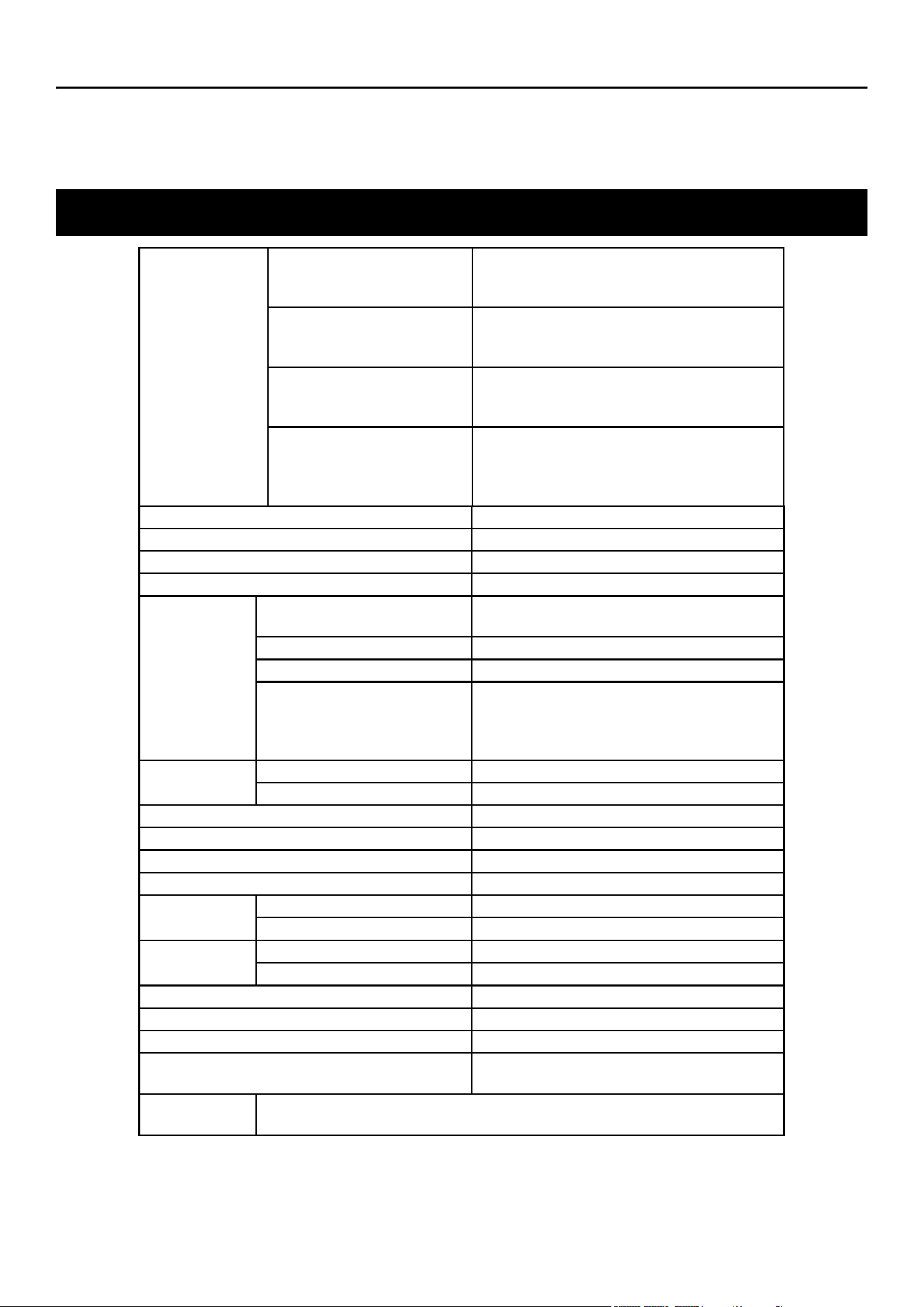
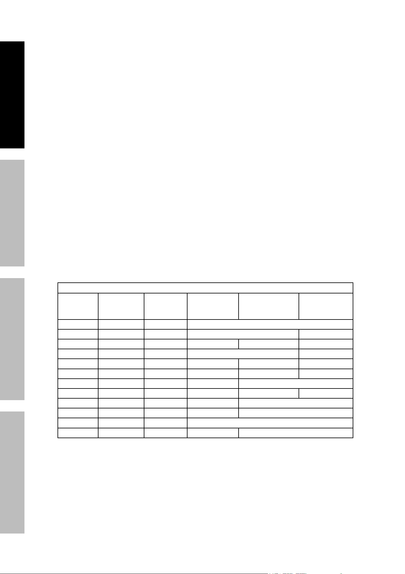
Specifications
Generator
AC Output
(Gasoline)
120 / 240 VAC, 60 Hz, 83.3 / 41.7 A, 1 Phase
10000 Running Watts
13000 Maximum Starting Watts
AC Output
(LPG / Propane)
120 / 240 VAC, 60 Hz, 75.8 / 37.9 A, 1 Phase
9100 Running Watts
12000 Maximum Starting Watts
AC Output
(Natural Gas)
120 / 240 VAC, 60 Hz, 65.0 / 32.5 A, 1 Phase
7800 Running Watts
10000 Maximum Starting Watts
Receptacles
4 x 120 VAC, 20 A GFCI
1 x 120 VAC, 30 A Twist Lock L5-30R
1 x 120 / 240 VAC, 30 A Twist Lock L14-30R
1 x 120 / 240 VAC, 50 A NEMA 14-50R
Displacement 458 cc
Compression Ratio 8.8:1
Engine Type Horizontal Single Cylinder, 4-stroke, OHV
Cooling System Forced air cooled
Fuel
Type
87+ octane, stabilizer-treated unleaded
gasoline; LPG / Propane; or Natural Gas
Gasoline Tank 10.7 Gallon / 40.5 Liter
LPG / Propane Tank 40 lb tank minimum
Natural Gas
Fuel Rating: 1000 BTU /cu ft
Minimum Fuel Supply Size: 1/2"
Supply Pressure: 5~9 WC (1.2-2.24 KPa)
Maximum Flow Rate: 125000 BTU / hr
Engine Oil
Type SAE 10W-30
Capacity 1.3 Quart / 1.2 Liter
Run Time @ 50% Load with full gasoline tank 12.1 hours
Run Time @ 50% Load with 100 lb LPG tank 16 hours
Sound Level at 23 feet, 50% load 78.5 dB (A)
Bore x Stroke 90 mm x 72 mm
Spark Plug
Type LG / Torch F7RTJC or equivalent
Gap 0.031"– 0.039"
Valve
Clearance
Intake 0.002"– 0.004"
Exhaust 0.002"– 0.004"
Engine Speed 3600 RPM
Electric Start Battery 12 V – 14 Ah Lead-Acid Non-Spillable
Remote Control Battery 3V CR2032
Internal Battery
3V CR2032
Contains non-replaceable batteries
Battery
Charger
Input: 100 –240 VAC, 50 / 60 Hz, 0.5 A Max
•
Output: 14 VDC, 0.8 A
Cable Length: 5.9 feet
The emissions control system for this Engine is warranted for standards set by the
U.S. Environmental Protection Agency. For warranty information, refer to the last pages of this manual.
In reference to the remote: Changes or modifications not expressly approved by Harbor Freight Tools
could void the user’s authority to operate the equipment. FCC ID: 2BBOR-QJ003
Page 4
For technical questions, please call 1-800-444-3353.
71386
SAFETY OPERATION MAINTENANCESETUP
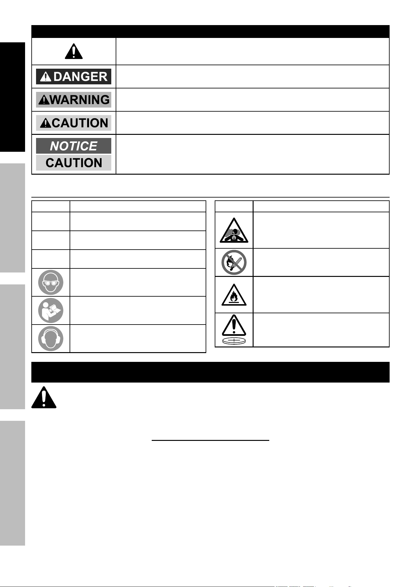
WARNING SYMBOLS AND DEFINITIONS
This is the safety alert symbol. It is used to alert you to potential
personal injury hazards. Obey all safety messages that
follow this symbol to avoid possible injury or death.
Indicates a hazardous situation which, if not avoided,
will result in death or serious injury.
Indicates a hazardous situation which, if not avoided,
could result in death or serious injury.
Indicates a hazardous situation which, if not avoided,
could result in minor or moderate injury.
Addresses practices not related to personal injury.
Symbol Definitions
Symbol Property or Statement
RPM
Revolutions Per Minute
HP
Horsepower
AWG
American Wire Gauge
WARNING marking concerning
Risk of Eye Injury. Wear ANSI-approved
safety goggles with side shields.
Read the manual before
set-up and/or use.
WARNING marking concerning
Risk of Hearing Loss.
Wear hearing protection.
Symbol Property or Statement
WARNING marking concerning
Risk of Respiratory Injury.
Operate engine OUTSIDE and far away
from windows, doors, and vents.
WARNING marking concerning
Risk of Fire while handling fuel.
Do not smoke while handling fuel.
WARNING marking concerning
Risk of Fire. Do not refuel while
operating. Keep flammable
objects away from engine.
WARNING: Contains coin battery.
IMPORTANT SAFETY INSTRUCTIONS
WARNING! Read all instructions.
Failure to follow all instructions listed below may result in fire, serious injury and/or DEATH.
The warnings and precautions discussed in this manual cannot cover all possible conditions and
situations that may occur. It must be understood by the operator that common sense and caution
are factors which cannot be built into this product, but must be supplied by the operator.
SAVE THESE INSTRUCTIONS

Page 5
For technical questions, please call 1-800-444-3353.
71386
SAFETYOPERATIONMAINTENANCE SETUP
Setup Precautions
1. This unit is to be installed so that access is
restricted to only qualified service personnel
who have been instructed of the reasons for the
restrictions applied to the location and about any
precautions that must be taken. Access shall be
through the use of a special tool, or lock and key,
or other means of security and shall be controlled
by the authority responsible for the location.
2. LPG / Propane and Natural Gas systems must
be installed and used in strict conformance
with NFPA 58 (Liquefied Petroleum Gas Code),
NFPA 54 (National Fuel Gas Code), manufacturer's
recommendations, and all relevant local,
state, and federal codes and regulations.
3. LPG / Propane, Natural Gas, and Gasoline fuel and
fumes are flammable, and potentially explosive. Use
proper fuel storage and handling procedures. Do
not store fuel or other flammable materials nearby.
4. Fire and explosion hazard. Never use a gas
container, LPG / Propane connector hose,
LPG / Propane tank, Natural Gas connector hose,
or any other fuel item that appears to be damaged.
5. Fire and explosion hazard. Only use approved
LPG / Propane tanks with an Overfilling Prevention
Device (OPD) valve. Keep the tank in a vertical
position with the valve on top and placed at
ground level on a flat surface. Do not allow tanks
to be near any heat source. When transporting
and storing, turn the propane tank valve to the
fully closed position and disconnect the tank.
Make sure to always cover the generator inlet
and tank outlet with protective plastic caps.
6. Connect LPG / Propane tank using provided
attachment kit only. Kit includes 1.5 meter
(4.9 ft) hose. Place tank as far away from
Generator as hose allows and away from engine
exhaust. Do not place tank above Generator.
7. Connect to Natural Gas source using PREDATOR
®
1/2" NG Quick Connect Hose Kit only, item 70491
(not included). Kit includes 7.6 meter (25 ft) Hose.
Do not use NG Hose with any other appliances.
8. Fire and explosion hazard. If there is a strong
smell of Propane or Natural Gas while operating
the generator, fully close the LPG / Propane tank
valve or NG shutoff valve and shut down the
Generator immediately. Once the LPG / NG is
off, use soapy water to check for leaks on the
hose and connections on the tank valve and the
generator. Do not smoke or light a cigarette or
check for leaks using any open flame source such
as a match or lighter. If a leak is found, contact
a qualified technician to inspect and repair the
LPG or NG system before using the generator.
9. Install carbon monoxide alarm(s) with battery
backup (not included) in nearby buildings
according to manufacturer’s instructions.
10. Have multiple ABC class fire extinguishers nearby.
11. Operation of this equipment may create sparks that
can start fires around dry vegetation.
A spark arrestor may be required. The operator
should contact local fire agencies for laws or
regulations relating to fire prevention requirements.
12. Set up and use only on a flat, level,
well-ventilated surface.
13. All connections and conduits from the Generator
to the load must only be installed by trained and
licensed electricians, and in compliance with all
relevant local, state, and federal electrical codes and
standards, and other regulations where applicable.
14. Connections for standby power to a building
electrical system must be made by a qualified
electrician. The connection must isolate the
Generator power from utility power, and must
comply with all applicable laws and electrical codes.
15. A transfer switch should be installed by a
licensed electrician in compliance with all
applicable laws and electrical codes.
16. Wear ANSI-approved safety goggles, heavy-duty
work gloves, and dust mask/respirator during set up.
17. Use only lubricants and fuel recommended
in the Specifications chart of this manual.
18. Improper connections to a building electrical system
can allow electrical current from the Generator
to backfeed into the utility lines. Such backfeed
may electrocute utility company workers or others
who contact the lines during a power outage,
and the Generator may explode, burn, or cause
fires when utility power is restored. Consult
the utility company and a qualified electrician if
intending to use the Generator for back up power.
19. Do not operate the Generator before grounding.
The Generator must be earth-grounded
in accordance with all relevant electrical
codes and standards before operation.
Page 6
For technical questions, please call 1-800-444-3353.
71386
SAFETY OPERATION MAINTENANCESETUP
Operating Precautions
1. CARBON MONOXIDE HAZARD
Using a generator indoors CAN KILL
YOU IN MINUTES. Generator exhaust
contains carbon monoxide. This is a
poison you cannot see or smell.
OFF
RUN
START
LOW OIL
OVERLOAD
OUTPUT
PARALLEL OUTLETS
RESET
AC 120V
RESET
DC 12V
ESC
THROTTLE
OFF
RUN
START
LOW OIL
OVERLOAD
OUTPUT
PARALLEL OUTLETS
RESET
AC 120V
RESET
DC 12V
ESC
THROTTLE
NEVER use inside a home or garage,
EVEN IF doors and windows are open.
OFF
RUN
START
LOW OIL
OVERLOAD
OUTPUT
PARALLEL OUTLETS
RESET
AC 120V
RESET
DC 12V
ESC
THROTTLE
Only use OUTSIDE and far away
from windows, doors, and vents.
Do not use in trailers, truck beds, or tents.
20′
20′
20′
20′
20′
Use at least 20 feet away from people,
animals,
and structures with exhaust pointed
away.
2. CARBON MONOXIDE SHUTOFF
DANGER! TO PREVENT SERIOUS
INJURY AND DEATH FROM
CARBON MONOXIDE INHALATION:
The Carbon Monoxide sensor is an additional
layer of protection only. Do not use the
Generator in any area or situation that will
allow carbon monoxide to accumulate.
• FLASHING RED LIGHT:
Dangerous levels of carbon monoxide gas have
built up and generator will shutoff.
Leave immediately until area has aired
out. Move Generator to well-ventilated
area before operation.
• FLASHING YELLOW LIGHT:
Carbon monoxide sensor malfunction.
Sensor needs service. Do not use the
Generator until the sensor is working
properly. For technical questions,
please call 1-800-444-3353.
NOTE: Yellow light flashes once after
starting to indicate passing self-check
and is functioning normally.
Carbon Monoxide sensor must only be serviced
by qualified technician to restore it to original
settings. Do not modify or tamper with the
Carbon Monoxide sensor. Not following these
instructions can result in death or serious injury
due to Carbon Monoxide sensor malfunction.
3. Generator will produce carbon monoxide
when burning gasoline, LPG, or NG.
4. Never use a generator indoors, including in
garages, basements, crawl spaces and sheds.
Opening doors and windows or using fans will NOT
prevent carbon monoxide build up in the home.
5. When using generators, keep them outdoors
and far away from open doors, windows,
and vents to avoid toxic levels of carbon
monoxide from building up indoors.
6. If you start to feel sick, dizzy, or weak while
using a generator, get to fresh air right away.
The carbon monoxide from generators can
quickly lead to full incapacitation and death.
7. LPG / Propane and Natural Gas are
highly flammable and explosive.
8. Flammable gas under pressure can
cause a fire or explosion if ignited.
9. LPG / Propane can settle in low places
because it is heavier than air.
10. LPG / Propane and Natural Gas have a distinctive
odor added to help detect potential leaks. This odor
can diminish over time or due to other factors.
11. Keep LPG / Propane tanks in an upright position.

Page 7
For technical questions, please call 1-800-444-3353.
71386
SAFETYOPERATIONMAINTENANCE SETUP
12. When exchanging LPG / Propane tanks, be
sure the tank valve is the same type.
13. In case of a LPG / Propane or Natural Gas
fire, do not attempt to extinguish unless
the fuel supply can be shut off safely.
14. LPG / Propane will burn the skin.
Prevent skin contact at all times.
15. Keep the LPG / Propane tank, LPG hose, and
Natural Gas hose away from engine exhaust.
16. Keep children away from the equipment,
especially while it is operating.
17. Fire Hazard! Do not fill gas tank while engine is
running. Do not operate if gasoline has been spilled.
Clean spilled gasoline before starting engine.
Do not operate near pilot light or open flame.
18. Do not touch engine during use.
Let engine cool down after use.
19. Never store fuel or other flammable
materials near the engine.
20. If the plugged in product operates abnormally
or unusually slow, immediately stop using the
generator as a power source. Read and adhere
to the instruction manual of the product to be
powered to make sure that it can be safely and
efficiently powered by a portable generator.
21. Before connecting an appliance or power cord
to the generator: Make sure that it is in good
working order. Faulty appliances or power cords
can create a potential for electrical shock.
22. Do not exceed the running wattage of the
generator. Make sure that the total electrical rating
of all of the tools or appliances plugged into the
generator at the same time does not exceed that
of the generator. Check that the startup surge
will not be beyond the limit of the generator.
23. Do not overload the generator. Even a
slight overload may lead to premature
generator failure and a substantial
overload will trip the circuit breaker.
24. Do not attempt to connect or disconnect
load connections while standing in water,
or on wet or soggy ground.
25. Do not touch electrically energized parts of
the generator and interconnecting cables or
conductors with any part of the body, or with
any non-insulated conductive object.
26. Connect the generator only to a load that is
compatible with the electrical characteristics
and running wattage of the generator.
27. Insulate all connections and disconnected wires.
28. GFCI PRECAUTIONS
Test Ground Fault Circuit Interrupter (GFCI)
receptacles before each use as follows:
a. Disconnect all devices from the Generator.
b. Start the engine.
c. Press Test button on receptacle
to trip the GFCI device.
d. The Reset button should extend, cutting
off electricity to the receptacle.
e. If above test fails, do not use receptacle
until it is repaired or replaced.
f. Press Reset button in for use.
Refer to Grounding on page 12.
29. Guard against electric shock.
Prevent body contact with grounded surfaces such
as pipes, radiators, ranges, and refrigerators.
30. Only use a suitable means of transport and
lifting devices with sufficient weight bearing
capacity when transporting the generator.
31. Secure the generator on transport vehicles to
prevent it from rolling, slipping, and tilting.
32. Industrial applications must follow
OSHA requirements.
33. Do not leave the generator unattended when it is
running. Turn off the generator (and remove safety
keys, if available) before leaving the work area.
34. The generator can produce high noise levels.
Prolonged exposure to noise levels
above 85 dBA is hazardous to hearing.
Wear ear protection when operating the generator
or when working nearby while it is operating.
35. Wear ANSI-approved safety glasses
and hearing protection during use.
36. People with pacemakers should consult their
physician(s) before use. Electromagnetic fields in
close proximity to a heart pacemaker could cause
pacemaker interference or pacemaker failure.
Caution is necessary when near the
engine’s magneto or recoil starter.
37. Use only accessories that are recommended
by Harbor Freight Tools for your model.
Accessories that may be suitable for one
piece of equipment may become hazardous
when used on another piece of equipment.
38. Do not operate in explosive atmospheres,
such as in the presence of flammable
liquids, gases, or dust. Gasoline-powered
engines may ignite the dust or fumes.
39. Stay alert, watch what you are doing and
use common sense when operating this
generator. Do not use while tired or under the
influence of drugs, alcohol or medication.
Page 8
For technical questions, please call 1-800-444-3353.
71386
SAFETY OPERATION MAINTENANCESETUP
40. Dress properly. Do not wear loose clothing or
jewelry. Keep hair, clothing and gloves away
from moving parts. Loose clothes, jewelry or
long hair can be caught in moving parts.
41. Parts, especially exhaust system components,
get very hot during use. Stay clear of hot parts.
42. Keep the stop / start remote control away from
children. Do not place in tight spaces with other
objects that may actuate the remote buttons and
send an undesired start signal to the generator.
43. Do not cover the generator during operation.
44. Keep the generator and surrounding
area clean at all times.
45. Do not smoke, or allow sparks, flames,
or other sources of ignition around the
equipment, especially when refuelling.
46. Use the equipment, accessories, etc.,
in accordance with these instructions and in
the manner intended for the particular type of
equipment, taking into account the working
conditions and the work to be performed.
Use of the equipment for operations different from
those intended could result in a hazardous situation.
47. Do not operate the equipment with known
leaks in the engine’s fuel system.
48. When spills of fuel or oil occur, they must be
cleaned up immediately. Dispose of fluids and
cleaning materials as per any local, state, or
federal codes and regulations. Store oil rags in
a bottom-ventilated, covered, metal container.
49. Keep hands and feet away from moving parts. Do
not reach over or across equipment while operating.
50. Before use, check for misalignment or binding of
moving parts, breakage of parts, and any other
condition that may affect the equipment’s operation.
If damaged, have the equipment serviced
before using. Many accidents are caused
by poorly maintained equipment.
51. Use the correct equipment for the application.
Do not modify the equipment and do not use the
equipment for a purpose for which it is not intended.
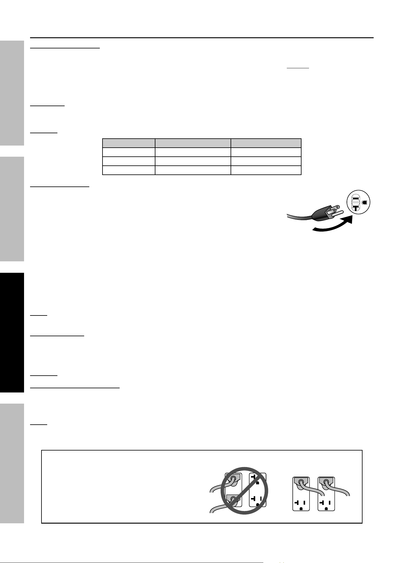
52. Extension Cord - Make sure your extension cord
is in good condition. When using an extension
cord, be sure to use one heavy enough to carry
the current your product will draw. An undersized
extension cord will cause a drop in line voltage
resulting in loss of power and overheating.
The table below shows the correct cord size to use
depending on cord length and nameplate ampere
rating. If in doubt, use the next heavier gauge.
The smaller the gauge number, the heavier the cord.
RECOMMENDED MINIMUM WIRE GAUGE FOR EXTENSION CORDS
CURRENT
(AMPS)
Load @
120 V
(WATTS)
Load @
240 V
(WATTS)
20 ~ 50 ft 50 ~ 75 ft 75 ~ 100 ft
2 240 480 18 AWG
4 480 960 18 AWG 16 AWG
6 720 1440 18 AWG 16 AWG 14 AWG
8 960 1920 16 AWG 12 AWG
10 1200 2400 16 AWG 14 AWG 12 AWG
15 1800 3600 14 AWG 12 AWG 10 AWG
20 2400 4800 12 AWG 10 AWG
25 3000 6000 12 AWG 10 AWG 8 AWG
30 3600 7200 10 AWG 8 AWG
35 4200 8400 8 AWG 6 AWG
40 4800 9600 6 AWG
45 5400 10,800 6 AWG 4 AWG
Do not use extension cords less than 20 feet in length.

Page 9
For technical questions, please call 1-800-444-3353.
71386
SAFETYOPERATIONMAINTENANCE SETUP
Battery Charger / Maintainer Precautions
1. Do not expose Battery Charger / Maintainer
to rain or snow.
2. Use of an attachment not recommended
or sold by the Battery Charger / Maintainer
manufacturer may result in a risk of fire,
electric shock, or injury to persons.
3. To reduce risk of damage to electric plug
and cord, pull by plug rather than cord when
disconnecting Charger / Maintainer.
4. Do not operate Charger / Maintainer with damaged
cord or plug – replace the cord or plug immediately.
5. Do not operate Charger / Maintainer if it has received
a sharp blow, been dropped, or otherwise damaged
in any way; take it to a qualified serviceman.
6. Do not disassemble Charger / Maintainer –
take it to a qualified technician when service
or repair is required. Incorrect reassembly
may result in a risk of electric shock or fire.
7. To reduce risk of electric shock, unplug
Charger / Maintainer from outlet before
attempting any maintenance or cleaning.
8. Locate Charger / Maintainer as far away
from Generator as power cord permits.
9. Maintain labels and nameplates on the
Charger / Maintainer. These carry important
safety information. If unreadable or missing,
contact Harbor Freight Tools for a replacement.
10. Unplug the Battery Charger / Maintainer from its
electrical outlet before connecting its power cord
to the Generator, or performing any inspection,
maintenance, or cleaning procedures.
11. Do not use Charger / Maintainer while tired or under
the influence of drugs, alcohol or medication.

Page 10
For technical questions, please call 1-800-444-3353.
71386
SAFETY OPERATION MAINTENANCESETUP
Service Precautions
1. Before service, maintenance, or cleaning:
a. Unplug all devices from the Generator.
b. Push the Engine / Battery Switch
to the "STOP" (OFF) position.
c. Turn the Fuel Selector Switch to
the “ STORAGE” position.
d. Allow the engine to completely cool.
e. Then, remove the spark plug cap
from the spark plug.
2. Keep all safety guards in place and in
proper working order. Safety guards include
muffler, air cleaner, mechanical guards,
and heat shields, among other guards.
3. Make sure the Engine/Battery Switch is in its
“STOP” position before moving the Generator
and before performing any service, maintenance,
or cleaning procedures on the unit.
4. Keep all electrical equipment clean and dry.
Replace any wiring where the insulation is
cracked, cut, abraded, or otherwise degraded.
Replace terminals that are worn, discolored, or
corroded. Keep terminals clean and tight.
5. Do not alter or adjust any part of the
equipment or its engine that is sealed by the
manufacturer or distributor. Only a qualified
service technician may adjust parts that may
increase or decrease governed engine speed.
6. Wear ANSI-approved safety goggles,
heavy-duty work gloves, and
dust mask/respirator during service.
7. Maintain labels and nameplates on the equipment.
These carry important information.
If unreadable or missing, contact
Harbor Freight Tools for a replacement.
8. Have the equipment serviced by a qualified repair
person using only identical replacement parts.
This will ensure that the safety of the equipment
is maintained. Do not attempt any service or
maintenance procedures not explained in this
manual or any procedures that you are uncertain
about your ability to perform safely or correctly.
9. Store equipment out of the reach of children.
10. Follow scheduled engine and
equipment maintenance.
GFCI Protection:
This Generator is equipped with two 3-Prong,
duplex 120 V ground fault circuit interrupter
(GFCI) receptacles. These outlets provide
additional protection from the risk of electric
shock. Should replacement of the receptacles
become necessary, use only identical replacement
parts that include GFCI protection.
Refueling:
1. Turn off the generator before refilling
the fuel tank. Do not refill the fuel tank
while the engine is running or hot.
2. Do not smoke, or allow sparks, flames,
or other sources of ignition around the
equipment, especially when refueling.
3. TO PREVENT FUEL LEAKAGE AND FIRE
HAZARD, Do Not fill fuel tank to the top.
Leave a little room for the fuel to expand as needed.
4. Refuel in a well-ventilated area only.
5. Wipe up any spilled fuel and allow excess
to evaporate before starting engine.
To prevent FIRE, do not start the engine
while the smell of fuel hangs in the air.
6. Do not connect LPG / Propane or NG fuel
sources to the Generator while operating with
gasoline. Shut down Generator and allow to
cool before connecting alternate fuel type.
Page 11
For technical questions, please call 1-800-444-3353.
71386
SAFETYOPERATIONMAINTENANCE SETUP
Button / Coin Battery Warnings
WARNING
• INGESTION HAZARD: This product contains
a button cell or coin battery.
• DEATH or serious injury can occur if ingested.
• A swallowed button cell or coin battery can cause
Internal Chemical Burns in as little as 2 hours.
• KEEP new and used batteries OUT OF REACH OF CHILDREN
• Seek immediate medical attention if a battery is suspected
to be swallowed or inserted inside any part of the body.
This symbol means:
INGESTION HAZARD: This product contains a
button cell or coin battery.
1. Remove and immediately recycle or dispose
of used batteries according to local regulations
and keep away from children. Do NOT dispose
of batteries in household trash or incinerate.
2. Even used batteries may cause
severe injury or death.
3. Call a local poison control center
for treatment information.
4. Non-rechargeable batteries are not to be recharged.
5. Do not force discharge, recharge, disassemble,
heat above 140° F or incinerate. Doing so
may result in injury due to venting, leakage
or explosion resulting in chemical burns.
6. Ensure the batteries are installed correctly
according to polarity (+ and -).
7. Do not mix old and new batteries, different
brands or types of batteries, such as alkaline,
carbon-zinc, or rechargeable batteries.
8. Remove and immediately recycle or dispose of
batteries from equipment not used for an extended
period of time according to local regulations.
9. Always completely secure the battery compartment.
If the battery compartment does not close
securely, stop using the product, remove the
batteries, and keep them away from children.
SAVE THESE INSTRUCTIONS.
Page 12
For technical questions, please call 1-800-444-3353.
71386
SAFETY OPERATION MAINTENANCESETUP
Set Up / Assembly
Read the ENTIRE IMPORTANT SAFETY INFORMATION section at the beginning of this manual
including all text under subheadings therein before set up or use of this product.
TO PREVENT SERIOUS INJURY AND FIRE: Operate only with proper spark arrestor installed.
Operation of this equipment may create sparks that can start fires around dry vegetation.
A spark arrestor may be required. The operator should contact local fire agencies for laws
or regulations relating to fire prevention requirements.
At high altitudes, the engine’s carburetor, governor,
and any other parts that control the fuel-air ratio will
need to be adjusted by a qualified mechanic to allow
efficient high-altitude use and to prevent damage to the
engine and any other devices used with this product.
Note: For additional information regarding the
parts listed in the following pages, refer to the
Assembly Diagram near the end of this manual.
NOTICE: This Generator is not intended to power
sensitive electronic equipment without the addition
of an appropriate line conditioner and surge
protector (both not included). Sensitive electronic
equipment includes, but is not limited to,
audio/video equipment, some television sets,
computers, and printers. Sensitive electronic
equipment should be operated on approved inverter-
type generators or pure sine wave generators.
Grounding
The Generator must be properly grounded in
accordance with all relevant electrical codes and
standards before operation. In many locations, local
code will not require this generator to be grounded
when used with cord and plug equipment plugged
directly into the receptacles on the generator. However,
your local regulations may require the generator to be
grounded. Contact a licensed electrician or consult
local authorities regarding local grounding requirements.
If grounding is required, have the unit grounded by a
qualified electrician if you are not qualified to do so.
General grounding instructions are as follows:
Use one of the following as the grounding electrode:
Pipe or conduit, minimum 3/4 in. diameter, minimum
8 ft. long. If steel, it must have anti-corrosion coating.
Rod, stainless steel or copper- or zinc-coated steel,
minimum 5/8 in. diameter, minimum 8 ft. long.
1. Drive electrode at least 8 ft.
vertically into the ground.
a. If rock layer prevents vertical entry, drive at an
angle not exceeding 45 degrees from vertical.
b. If rock layer prevents angle entry, bury electrode
in horizontal trench at least 30 in. deep.
2. The upper end of electrode must be
protected if above ground level.
3. Connect a #6 AWG grounding wire (not included)
from the Grounding Terminal on the Generator
Control Panel to the buried electrode.
For additional information on grounding methods,
please see the National Electrical Code.
NOTICE: There is a permanent conductor
between the portable generator stator winding
(Neutral Conductor) and the frame.
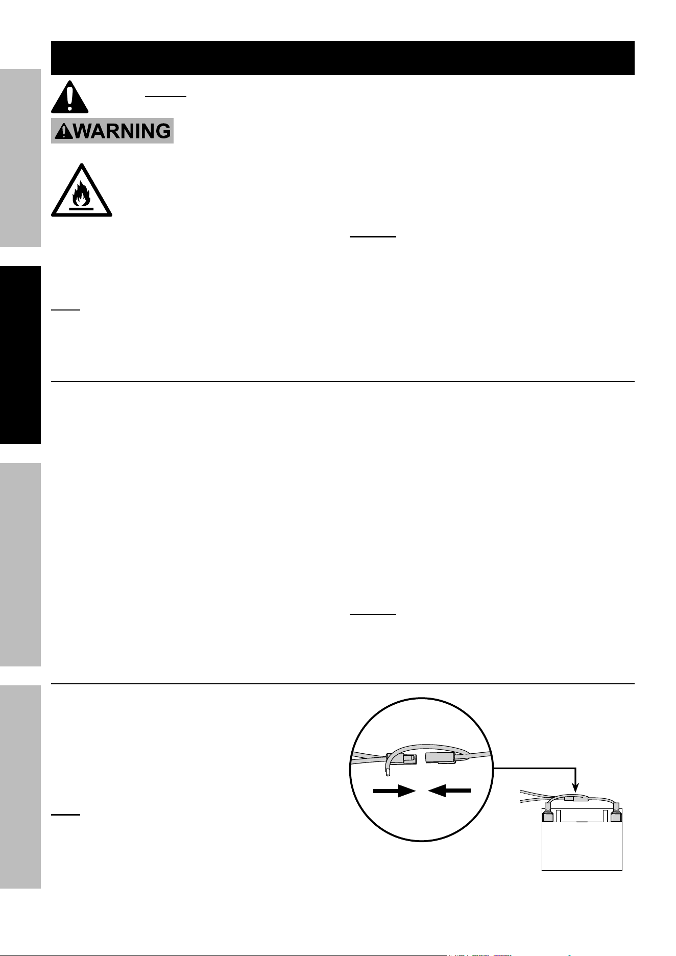
12 VDC Battery Connection
For the electric start and auto-choke functions, or to
operate on LPG or NG fuel, the included 12 VDC Battery
must be connected and charged before first use.
1. Push Engine / Battery Switch to
STOP (OFF) position.
2. Connect the two ends of the Battery
Quick Connector together.
Note: The built-in charging circuit charges the
Battery while the Engine is running. Turn the
Engine / Battery Switch off and use the Battery
Charger / Maintainer to keep the Battery charged
when the Generator is not in use or in storage.
Refer to 12 VDC Battery: in Storage on page 32.
Page 13
For technical questions, please call 1-800-444-3353.
71386
SAFETYOPERATIONMAINTENANCE SETUP
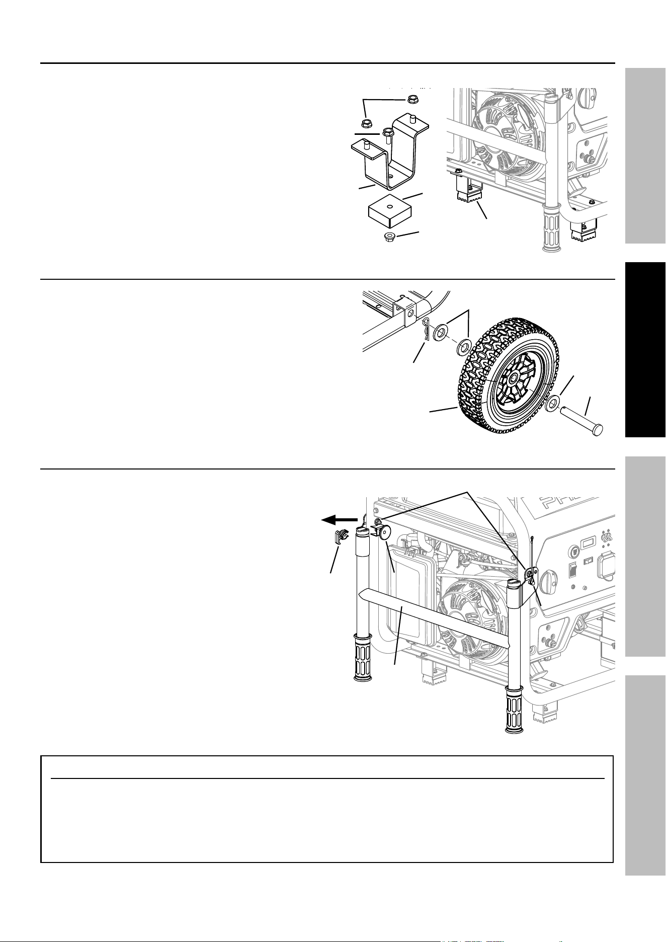
Foot Assembly
The Feet are installed on the air filter side of the Generator.
1. Prepare a set of 4 x 4 blocks on level ground. With
assistance, place the Generator on the blocks.
2. Secure one Foot (168) onto a Foot Bracket (169)
using a Hex Bolt (171) and Hex Flange
Nut (158). Repeat for other Foot and Bracket.
3. Align studs on Foot Bracket assembly with
holes on bottom of Generator frame and secure
in place with two Hex Flange Nuts (170).
Repeat for other Foot Bracket assembly.
Wheel Assembly
1. Slide one Wheel (174) and two Flat Washers (173)
onto a Wheel Axle (172), one Washer on each side
of Wheel.
2. Insert the Wheel Axle through the bracket on
the bottom of the Generator frame. Place
a third Flat Washer onto the Axle and
secure all in place with an R-Clip (175).
3. Repeat steps 1 and 2 for other Wheel assembly.
Handle Assembly
The Handle is installed on the air filter side of the Generator.
1. Align the holes in the brackets on
the Handle (177) with the holes
on the Generator frame.
2. Fasten in place using a Step Bolt (180)
and Flange Lock Nut (181), one
set on each side of Handle.
3. Remove and discard the yellow shipping clip
located on the Handle Release Pin (178).
4. Insert the Locking Pin (183) into the hole on the right
side of the Generator frame.
183183
177
178178
180, 181
177177
Shipping
Clip
168
171
169
170
158
Foot
Assembly
in place
174
173
173
172
175
Handle Operation
1. To unfold the Handle for use, first remove the
Locking Pin, then pull out the Handle Release
Pin and lift the Handle up. With the Handle lifted
into position, release the Handle Release Pin,
then insert the Locking Pin back into place.
2. To fold the Handle down after use, first remove
the Locking Pin, then pull out the Handle Release
Pin and push the Handle down. With the Handle
in position, release the Handle Release Pin,
then insert the Locking Pin back into place.
Page 14
For technical questions, please call 1-800-444-3353.
71386
SAFETY OPERATION MAINTENANCESETUP
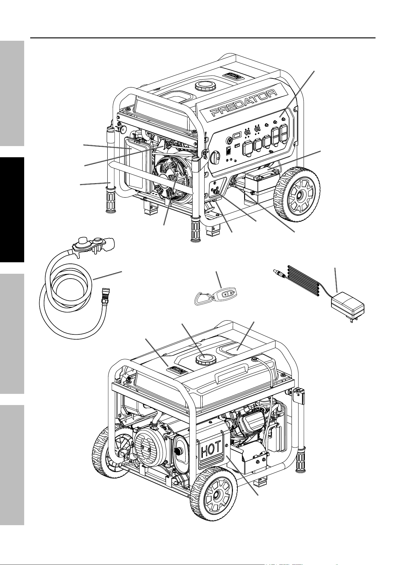
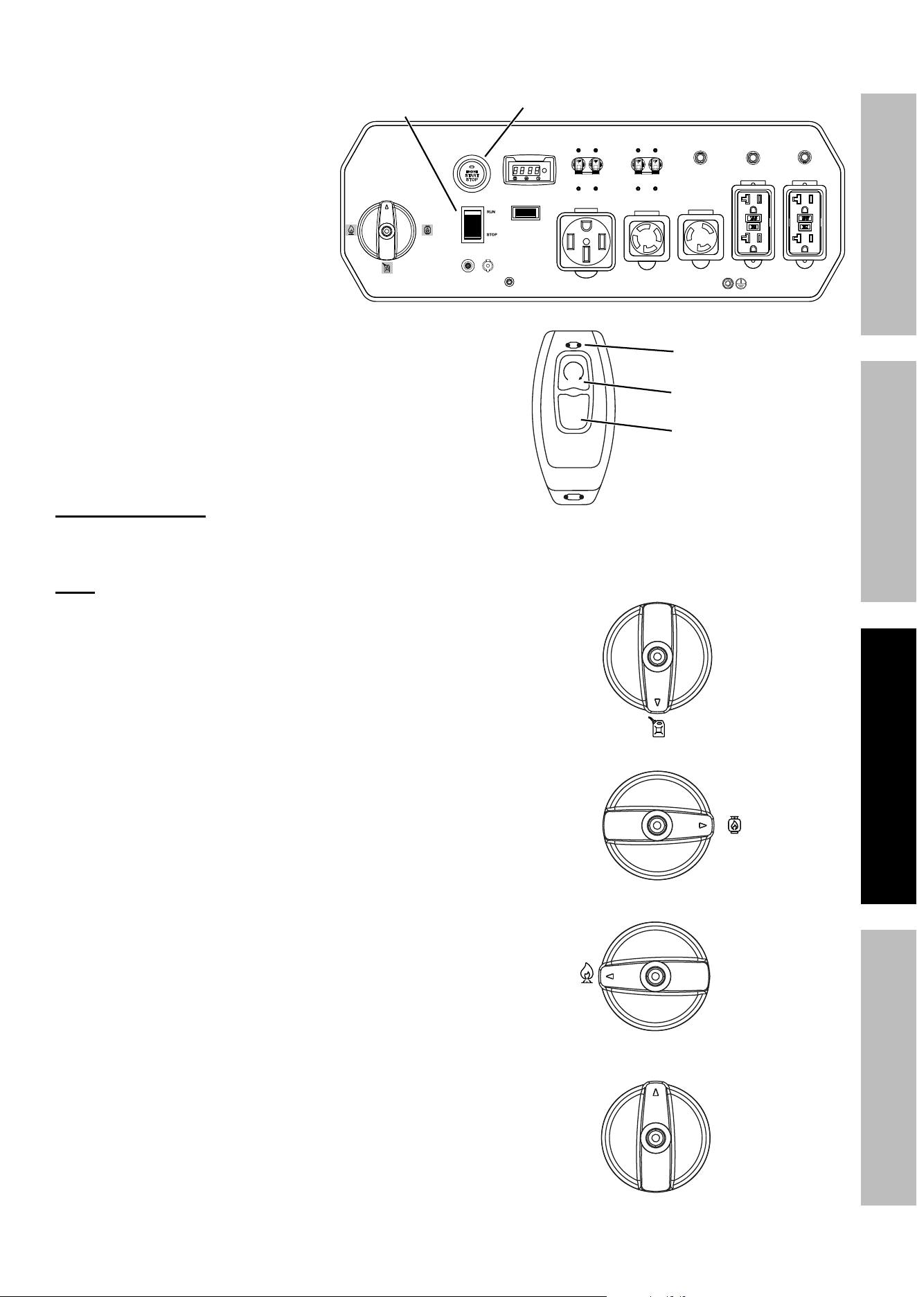
Components and Controls
Fuel Cap
Fuel Gauge
Muffler
Fuel Tank
Remote
Control
Battery
Charger / Maintainer
LPG / Propane
Attachment
Kit
Control
Panel
Handle
Gasoline
Fuel Valve
Battery
Starter
Handle
LPG / NG
Inlet
Air Filter
Oil Fill
Cap / Dipstick
Oil
Drain Plug
Page 15
For technical questions, please call 1-800-444-3353.
71386
SAFETYOPERATIONMAINTENANCE SETUP
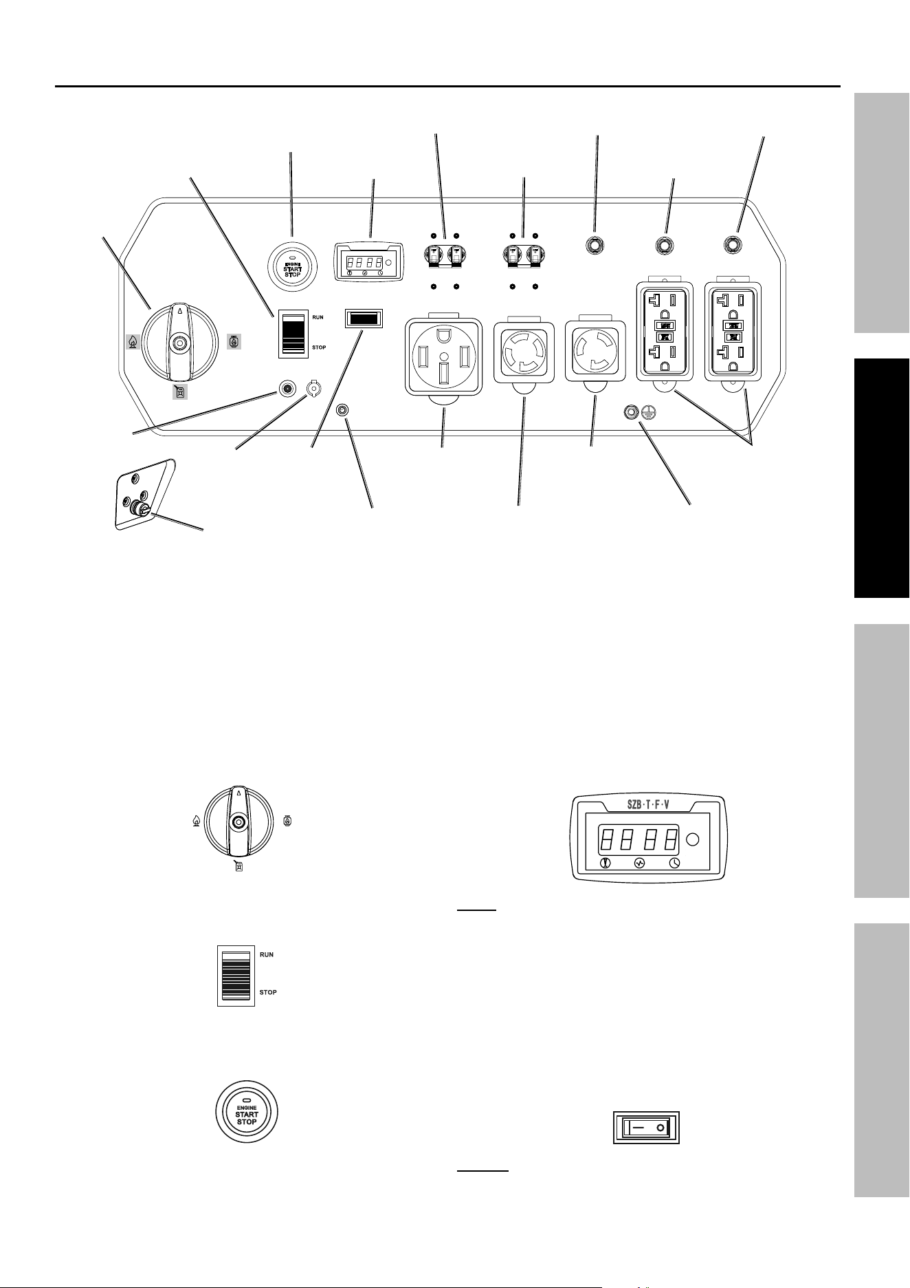
Components and Controls (continued)
OFF/STORAGE
GA SOLINE
PR OPANE
NG
LPG / NG
Inlet
Fuel
Selector
Switch
Ground
Terminal
120 VAC
20 A GFCI
Receptacles
(5-20R)
Low Oil
Alarm
Digital
Display
Engine
Stop / Start
Switch
Engine / Battery
Switch
Automatic
Idle Down
Switch
120 / 240 VAC
50 A Receptacle
(14-50R)
120 / 240 VAC
30 A Receptacle
(L14-30R)
120 VAC 30 A
Receptacle
(L5-30R)
AC Breaker
42 A 120 / 240 V
AC Breaker
30 A 120 / 240 V
AC Breaker
30 A 120 V
AC Breaker
20 A 120 V
AC Breaker
20 A 120 V
CO Sensor
Light
Battery
Charging
Port
Control Panel
The following are descriptions of the controls
on the Control Panel. Your Generator has
sockets to power your products with circuit
breakers to protect the voltage flow.
1. Fuel Selector Switch: Used to select from three
fuel types - Gasoline, LPG / Propane, or Natural Gas.
Storage position shuts off flow of all fuel types.
OFF/STORAG E
GASOLI NE
PROP AN E
NG
2. Engine / Battery Switch: Push to RUN position to
enable starting remotely, electrically, or manually.
3. Engine Stop / Start Switch: Used to
start and stop the Engine.
4. Digital Display: Press the Mode Button to
cycle through the Display’s functions:
• Voltage
(Displays U + voltage reading. Example: "U240")
• Frequency
(Displays F + frequency reading. Ex.: "F60")
• Current session runtime
• Total (accumulated) runtime
MODE
Note: Every 50 hours, a blinking maintenance
reminder will appear on the screen (P050, P100,
P150, etc.) See Page 28 for maintenance
schedule. To clear a maintenance reminder, press
and hold the Mode Button for 5 seconds.
5. Automatic Idle Down Switch: Used to turn the
Engine Idle function ON or OFF. In ON position
Engine speed (and frequency) is reduced when no
load is detected. Engine runs at full speed (and
frequency) when load above 75 W is applied.
ON OFF
Notice: Turn Automatic Idle Switch OFF
when connected load is less than 300 W.
Page 16
For technical questions, please call 1-800-444-3353.
71386
SAFETY OPERATION MAINTENANCESETUP
6. CO Sensor Light: Flashing red light indicates
dangerous levels of carbon monoxide gas
have built up. Flashing yellow light indicates
a carbon monoxide sensor malfunction.
Refer to Carbon Monoxide Shutoff on
page 25 for further information.
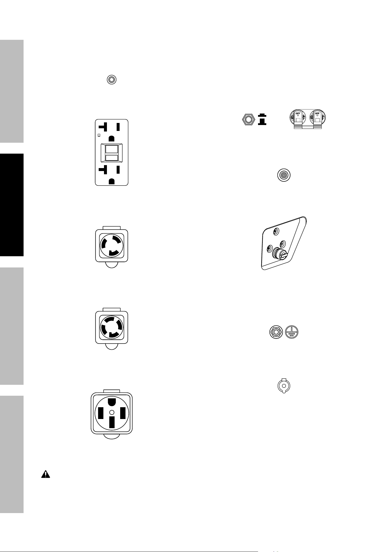
7. AC Receptacles: The Generator contains several
AC Receptacles to power tools and equipment.
a.
RESET
TEST
RESET
TEST
3-Prong, duplex
120 volt GFCI receptacle
(NEMA 5-20R)
b. 3-Prong, twistlock,
120 volt 30 A receptacle
(NEMA L5-30R)
c. 4-Prong, twistlock,
120 / 240 volt 30 A receptacle
(NEMA L14-30R)
d. 4-Prong, 120 / 240 volt,
50 A receptacle
(NEMA 14-50R)
WARNING! TO PREVENT SERIOUS INJURY:
Connect tools and equipment only to the Receptacle
(120 volt or 240 volt) that is compatible with the
electrical characteristics and rated capacities
of the tools and equipment being used.
8. Circuit Breakers: The circuit breaker protects
the Generator from overloading. The rating of
the breaker and the load it protects are marked
near the breaker. Should any of the Circuit
Breakers trip, the Generator will stop the electricity
output. If this happens, unplug all loads from
the Generator. Then, turn the tripped Circuit
Breaker to ON and re-attach loads gradually.
Note: For push-type Circuit Breakers allow a
few minutes for cool-down before resetting.
ON
OFF
9. Low Oil Alarm: If the Engine oil level is too
low, the LOW OIL ALARM light turns on and
the Engine will automatically shut off.
10. LPG/Propane and Natural Gas Connector:
Used to connect LPG / NG hose to Generator.
11. Grounding Terminal: Prior to each use, set
up the ground wire (not included) connection to
the Grounding Terminal to properly ground the
Generator. Refer to Grounding on page 12
for instructions on grounding the Generator.
12. Battery Charging Port: Used to charge
the 12 VDC Generator Battery using the
provided Battery Charger / Maintainer.
Page 17
For technical questions, please call 1-800-444-3353.
71386
SAFETYOPERATIONMAINTENANCE SETUP
High Altitude Operation Above 3000 feet
WARNING! TO PREVENT SERIOUS INJURY FROM FIRE:
Follow instructions in a well-ventilated area away from ignition sources.
If the Engine is hot from use, shut the engine off and wait for it to cool before proceeding. Do not smoke.
NOTICE: Warranty void if necessary adjustments are not made for high altitude use.
At high altitudes, the engine’s carburetor, governor, and any other parts that control the fuel-air ratio will need
to be adjusted by a qualified mechanic to allow efficient high-altitude use and to prevent damage to the engine
and any other devices used with this product. The fuel system on this engine may be influenced by operation
at higher altitudes. Proper operation can be ensured by installing an altitude kit at altitudes higher than 3000 ft.
above sea level. At elevations above 8000 ft., the engine may experience decreased performance, even with
the proper main jet. Operating this engine without the proper altitude kit installed may increase the engine’s
emissions and decrease fuel economy and performance. The kit should be installed by a qualified mechanic.
Note: Not all Generator models have a Solenoid. Skip those steps if a Solenoid is not present.
1. Turn off the Engine and close the gasoline Fuel Valve.
2. Turn the Fuel Selector Switch to the STORAGE position.
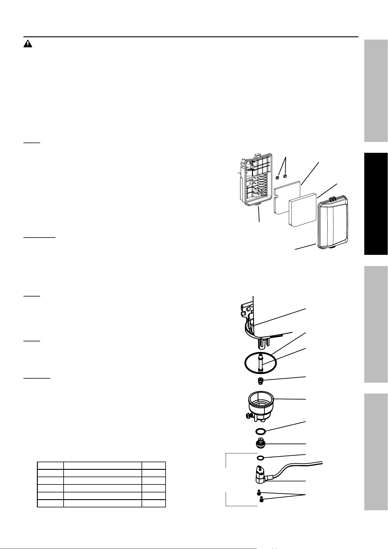
3. Move Air Cleaner Housing aside to allow access to the Carburetor:
a. Remove Air Cleaner Cover.
b. Remove foam filter and deflecting plate.
c. Remove Nuts to allow Air Cleaner Housing to be moved aside.
4. Place a bowl under the Fuel Cup to catch any spilled fuel.
5. Unthread the screws holding the Solenoid in place.
CAUTION! Carburetor bowl may have gas in it which
will leak upon removing the Solenoid / Bolt.
6. Disconnect the Solenoid and Solenoid Seal from the Bolt.
7. Unthread the Bolt holding the Fuel Cup.
8. Remove the Bolt, Bolt Seal, Fuel Cup, Fuel Cup Seal and Main Jet from the body of the Carburetor assembly.
A carburetor screwdriver (not included) is needed to remove and install the Main Jet.
Note: The mixing tube is held in place by the Main Jet and
might fall out when it is removed. If it falls out, replace it
in the same orientation before replacing the Main Jet.
9. Replace the Main Jet with the replacement Main Jet
needed for your altitude range (part 1a or 2a).
Note: The Fuel Cup Seal and Bolt Seal may be damaged during
removal and should be replaced with the new ones from the kit.
10. Replace the Fuel Cup Seal (4a), Fuel Cup,
Bolt Seal (3a), and Bolt. Tighten in place.
NOTICE: Do not cross thread bolt when tightening. Finger tighten first
and then use a wrench to make sure the bolt is properly threaded.
11. Replace the Solenoid and Solenoid Seal (5a),
and tighten in place with screws.
12. Reassemble the Air Cleaner and reattach all hoses to it.
13. Wipe up any spilled fuel and allow excess to evaporate
before starting Engine. To prevent FIRE, do not start
the Engine while the smell of fuel hangs in the air.
High Altitude Kit Parts List - A
Part Description Qty
1a Main Jet 3000-6000 ft. 1
2a Main Jet 6000-8000 ft. 1
3a Bolt Seal 1
4a Fuel Cup Seal 1
5a Solenoid Seal 1
Air Cleaner
Housing
Nuts
Deflecting
Plate
Foam
Filter
Air Cleaner
Cover
Carburetor
Assembly
Main Jet
Fuel Cup Seal
Mixing Tube
(might remain
inside carburetor)
Fuel Cup
Bolt Seal
Bolt
Solenoid
Solenoid Seal
Screws
Not present
on some
Generators
Page 18
For technical questions, please call 1-800-444-3353.
71386
SAFETY OPERATION MAINTENANCESETUP
Operation
Read the ENTIRE IMPORTANT SAFETY INFORMATION section at the beginning of this manual
including all text under subheadings therein before set up or use of this product.
Pre-Start Checks
Only operate the generator outside and at least 20 feet away from people, animals, and structures, with
exhaust pointed away. Inspect Engine and Generator looking for damaged, loose, and missing parts
before set up and starting. If any problems are found, do not use equipment until fixed properly.
Checking and Filling Engine Oil
NOTICE: Generator is shipped without engine
oil. Engine’s crankcase MUST be filled with
oil before first use. Your Warranty is VOID if
the Engine’s crankcase is not properly filled
with oil before first use and before each use
thereafter. Before each use, check the oil level.
Engine will not start with low or no engine oil.
1. Make sure the Engine is stopped and is level.
2. Clean the top of the Oil Fill Cap / Dipstick
and the area around it. Remove the
Cap / Dipstick by turning it counterclockwise
and wipe it off with a clean, lint free rag.
3. Add the appropriate type of oil until the oil level is at
the proper level. SAE 10W-30 oil is recommended
for general use. The SAE Viscosity Grade chart on
page 29 in the Maintenance section shows other
viscosities to use in different average temperatures.
Full Level
Full Level
4. Reinsert the Dipstick without threading it in and
remove it to check the oil level. The oil level
should be up to the edge of the hole as shown.
5. Thread the Oil Fill Cap / Dipstick back in clockwise.
NOTICE: Do not run the engine with too little oil.
Engine will shut off if engine oil level is too low.
For Gasoline Operation : Checking and Filling Fuel
WARNING! TO PREVENT SERIOUS
INJURY FROM FIRE:
Fill the fuel tank in a well-ventilated area
away from ignition sources. If the Engine
is hot from use, shut the Engine off and
wait for it to cool before adding fuel. Do not smoke.
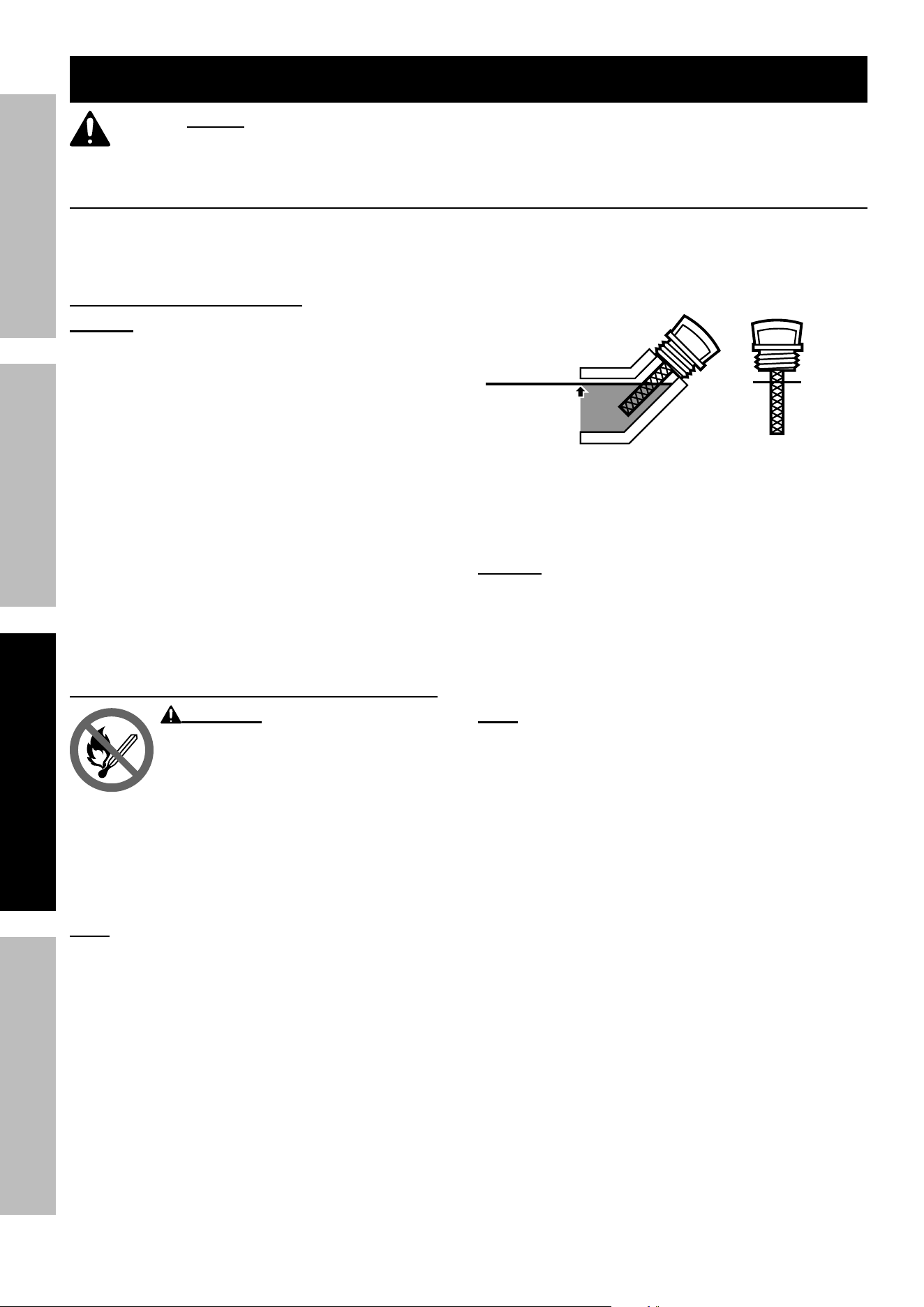
1. Clean the Fuel Cap and the area around it.
2. Unscrew and remove the Fuel Cap.
3. Remove the Strainer and remove any dirt
and debris. Then replace the Strainer.
Note: Do not use gasoline containing more than
10% ethanol (E10). Do not use E85 ethanol. Add fuel
stabilizer to the gasoline or the Warranty is VOID.
Note: Do not use gasoline that has been stored in a
metal fuel container or a dirty fuel container. It can
cause particles to enter the carburetor, affecting
Engine performance and/or causing damage.
4. If needed, fill the Fuel Tank to about 1 inch under
the fill neck of the Fuel Tank with 87 octane or
higher unleaded gasoline that has been treated
with a fuel stabilizer additive. Follow fuel stabilizer
manufacturer’s recommendations for use.
5. Replace the Fuel Cap.
6. Wipe up any spilled fuel and allow excess
to evaporate before starting engine.
To prevent FIRE, do not start the engine
while the smell of fuel hangs in the air.
Page 19
For technical questions, please call 1-800-444-3353.
71386
SAFETYOPERATIONMAINTENANCE SETUP
For LPG Operation : Connecting LPG / Propane Tank
a. LPG / Propane and Natural Gas systems must be installed and used in strict conformance with
NFPA 58 (Liquefied Petroleum Gas Code), NFPA 54 (National Fuel Gas Code), manufacturer's
recommendations, and all relevant local, state, and federal codes and regulations.
b. The LPG / Propane tank capacity must be minimum 40 lb or larger to avoid tank freezing
during use. Tank must conform to the standard as listed in Setup Precautions section.
c. Propane tanks that use a liquid withdrawal system cannot be
used with this Generator.
d. Verify the re-qualification date on the tank has not expired.
e. Connect LPG / Propane tank using provided attachment kit only. Kit includes
1.5 meter (4.9 ft) Hose. Place tank as far away from Generator as Hose allows
and away from engine exhaust. Do not place tank above Generator.
Do not use included LPG / Propane Hose with any other appliances.
f. All new tanks or used tanks that have not been plugged or kept closed
must be purged of air and moisture by a propane supplier prior to filling.
g. Position the tank so the connection between the tank valve and the
LPG / NG Inlet will not cause sharp bends or kinks in the Hose.
h. Inspect the LPG / Propane Hose before every use.
Do not use damaged equipment. If damage is detected,
have the problem corrected before further use.
WARNING! EXPLOSION HAZARD.
TO PREVENT SERIOUS INJURY:
Do not start the engine if the smell of
LPG / Propane hangs in the air. Close the
propane tank valve and disconnect the
LPG / Propane hose from the Generator when not in use.
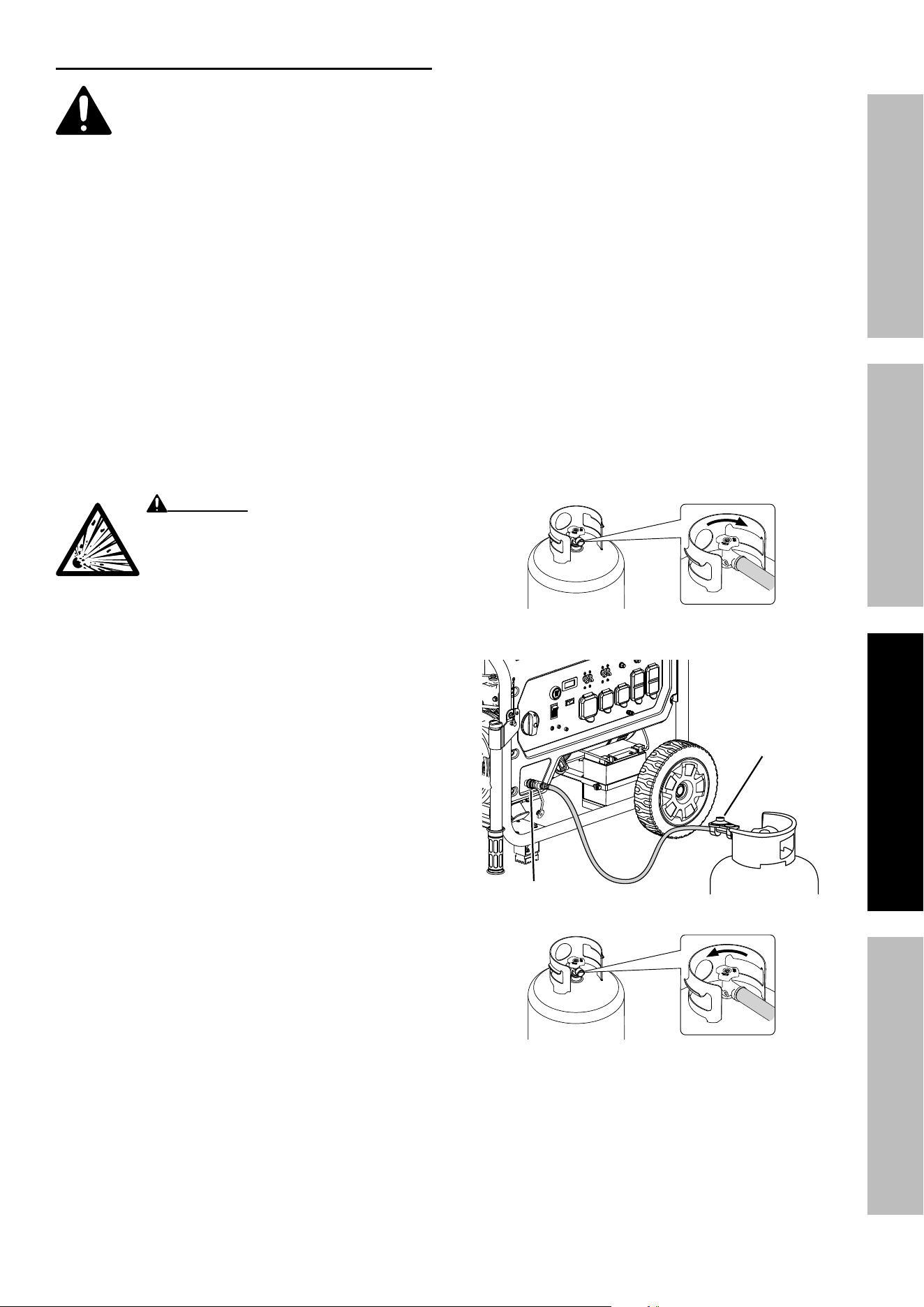
1. Turn the Generator OFF and place on a
flat surface in a well ventilated area.
2. Verify that the propane tank valve
is in the fully closed position.
3. Attach the Quick Connect Adapter
on the LPG / Propane Hose to the
LPG / NG Inlet on the Generator.
4. Remove the safety plug or cap from
the propane tank valve.
5. Attach the other end of the Hose to the
LPG / Propane connector on the tank.
Hand tighten clockwise to a positive
stop. To prevent damage, do not use a
wrench or tool to tighten the connector.
6. Turn the propane tank valve to the fully open
position. Check for leaks by applying soapy water
to all connections. Look for bubbles. If bubbles
are present at connections, close the propane tank
valve and tighten connections. Open the valve
and recheck connections. If a leak continues or
is not at a connection do not use the Generator.
Have the problem corrected before further use.
Close Tank Valve
Open Tank Valve
LPG / NG Inlet
LPG / Propane
Hose
Page 20
For technical questions, please call 1-800-444-3353.
71386
SAFETY OPERATION MAINTENANCESETUP
For Natural Gas Operation : Connecting to NG Source
a. LPG / Propane and Natural Gas systems must be installed and used in strict conformance with
NFPA 58 (Liquefied Petroleum Gas Code), NFPA 54 (National Fuel Gas Code), manufacturer's
recommendations, and all relevant local, state, and federal codes and regulations.
b. Natural Gas source must meet requirements listed in Specifications chart on page 3.
c. Connect to Natural Gas source using PREDATOR
®
1/2" NG Quick
Connect Hose Kit only, item 70491 (not included). Kit includes
7.6 meter (25 ft) Hose. Do not use NG Hose with any other appliances.
d. An NG shutoff valve (not included) must be installed before connecting
the NG Hose. Do not connect NG Hose directly to the NG source.
e. Position the Generator so the connection between the NG shutoff valve
and the LPG / NG Inlet will not cause sharp bends or kinks in the Hose.
f. Make sure the NG source location and the NG Hose allow the Generator
to be located at least 20 feet from any occupied spaces.
g. Inspect the NG Hose before every use. Do not use damaged equipment.
If damage is detected, have the problem corrected before further use.
WARNING! EXPLOSION HAZARD. TO PREVENT SERIOUS INJURY:
Do not start the engine if the smell of Natural Gas hangs in the air. Close the
NG shutoff valve and disconnect the NG hose from the Generator when not in use.
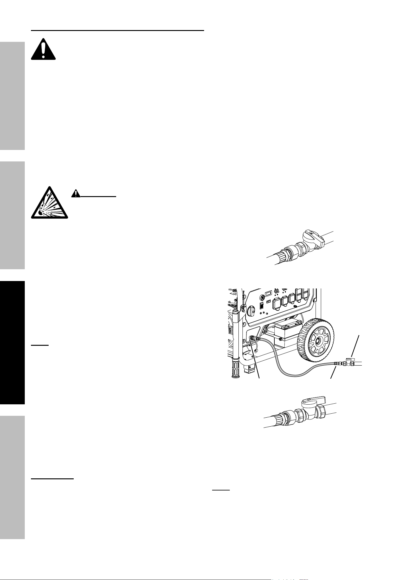
1. Turn the Generator OFF and place on a
flat surface in a well ventilated area.
2. Verify that the NG shutoff valve is
in the fully closed position.
3. Attach the Quick Connect Adapter on the
NG Hose to the LPG / NG Inlet on the Generator.
4. Connect the Coupling from the NG Hose
Kit to the shutoff valve, then connect the
NG Hose assembly to Coupling.
Note: Natural gas pipe sealant, joint
compound, or the proper type of PTFE tape
must be used ONLY for the connection
from the Coupling to the shutoff valve.
5. Turn the NG shutoff valve to the fully open position.
Check for leaks by applying soapy water to all
connections and joints. Look for bubbles. If bubbles
are present at connections, close the shutoff
valve and tighten connections. Open the valve
and recheck connections. If a leak continues or
is not at a connection do not use the Generator.
Have the problem corrected before further use.
Remote Start
The Start / Stop Remote Control will operate up
to approximately 100 feet in distance from the
Generator. The distance at which the Remote will
function may be adversely affected by obstructions
between the Generator and the Remote Control.
Note: The operational range of the Remote Control may
decrease as the battery in the Remote become depleted.
Remote replacement battery: CR2032
LPG / NG Inlet
NG Hose
NG
Shutoff
Valve
Close NG
Shutoff Valve
Open NG
Shutoff Valve
Page 21
For technical questions, please call 1-800-444-3353.
71386
SAFETYOPERATIONMAINTENANCE SETUP
Reprogramming the Start/Stop Remote Control
If the Start/Stop Remote Control is
replaced or needs to be paired to the
generator, follow this procedure:
1. Push the Engine/Battery Switch
to the RUN (ON) position.
2. Push and hold the Engine Start /
Stop Switch for 10 seconds until
the Switch Indicator Light flashes
green, then release the Switch.
3. Push the 2x button on the Stop/Start Remote
Control. It will pair with Generator and the Switch
Indicator Light on the Generator will stop flashing.
Fuel Selector Switch
Turn the Fuel Selector Switch on the Control
Panel to the desired fuel setting.
Note: The Engine is equipped with a safety solenoid
valve — Battery must be connected and charged
to allow operation with LPG or NG fuel.
1. To operate the Generator on gasoline turn the
Fuel Selector Switch to the GAS setting.
2. To operate the Generator on LPG / Propane turn the
Fuel Selector Switch to the PROPANE setting.
3. To operate the Generator on Natural Gas turn
the Fuel Selector Switch to the NG setting.
4. When the Generator is not in use turn the
Fuel Selector Switch to the OFF/ STORAGE
position to turn off all fuel flow to Engine.
OFF/ST OR AGE
GA SOLINE
PR OPANE
NG
Engine / Battery
Switch
Engine Stop / Start
Switch
2x
OFF
Remote Control
Activation Light
OFF Button
ON (2x) Button
G A SOLINE
PR OPANE
NG
OFF/STORAGE
Page 22
For technical questions, please call 1-800-444-3353.
71386
SAFETY OPERATION MAINTENANCESETUP
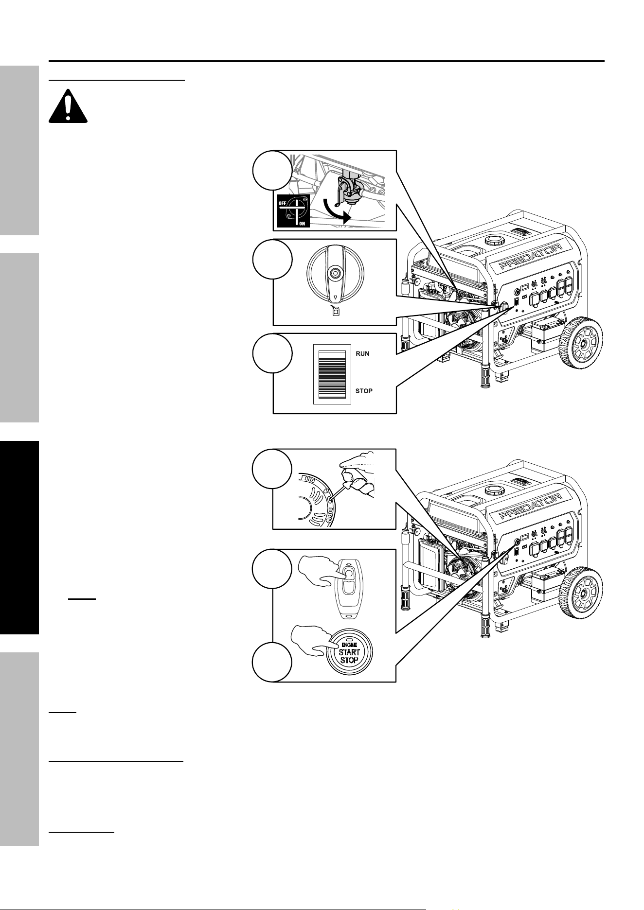
Starting the Engine – Gasoline Operation
Before Starting the Engine
a. Inspect the generator and engine.
b. Disconnect all electrical loads from the generator.
c. Fill the engine with the proper amount and type of
both stabilizer-treated unleaded gasoline and oil.
1. Open gasoline Fuel Valve.
2. Turn the Fuel Selector Switch
to the GASOLINE setting.
3. Push the Engine / Battery
Switch to the RUN position.
Select a starting method:
4. Manual Start: Grip the Starter
Handle of the Engine loosely
and pull it slowly several times
to allow gasoline to flow into the
Engine’s carburetor. Then pull
the Starter Handle gently until
resistance is felt. Allow Cable to
retract fully and then pull it quickly.
Repeat until the Engine starts. Do
not let the Starter Handle snap back
against the housing. Hold it as it
recoils so it doesn't hit the housing.
5. Remote Start: Slowly press and
release the 2x Button on the
Stop / Start Remote Control twice.
Note: If a CO shutoff event has
occurred the remote start capability
will be disabled until the Generator
Engine has been restarted by
another method.
6. Electric Start: Slowly press
and release the Engine
Start / Stop Switch twice.
Note: The Engine is equipped with an auto-choke system which requires the battery to be
charged to operate. If battery is dead, use the mechanical choke override located above the
carburetor to manually choke and unchoke the Engine and start the Engine manually.
If engine does not start:
• Check engine oil level.
Engine will not start with low or no engine oil.
• Check spark arrestor cleanliness.
Engine will not start if spark arrestor is clogged.
IMPORTANT: Allow the Engine to run at no load for five minutes after each start-up so that the Engine can stabilize.
2
3
GA SOLINE
1
4
5
6
2x
OFF
2x
2x
Page 23
For technical questions, please call 1-800-444-3353.
71386
SAFETYOPERATIONMAINTENANCE SETUP
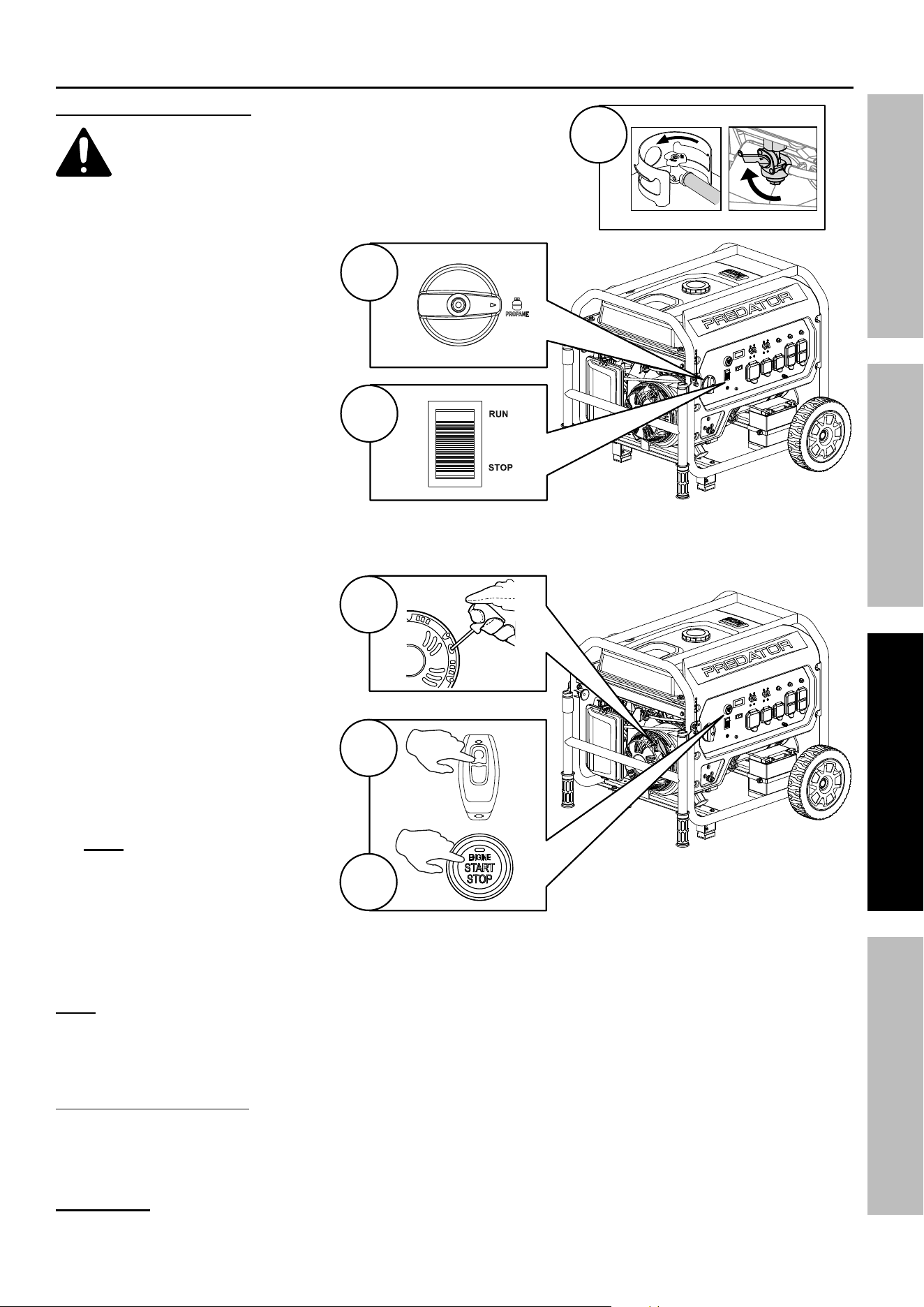
Starting the Engine – LPG / Propane Operation
Before Starting the Engine
a. Inspect the generator and engine.
b. Disconnect all electrical loads from the generator.
c. Make sure the LPG / Propane hose is correctly
connected to the generator and propane tank.
d. Make sure Battery is connected and charged.
1. Fully open the valve on the
LPG / Propane tank. Close
gasoline Fuel Valve if open.
2. Turn the Fuel Selector Switch
to the PROPANE setting.
3. Push the Engine / Battery
Switch to the RUN position.
Select a starting method:
4. Manual Start: Grip the Starter
Handle of the Engine loosely
and pull it slowly several times
to allow gasoline to flow into the
Engine’s carburetor. Then pull
the Starter Handle gently until
resistance is felt. Allow Cable to
retract fully and then pull it quickly.
Repeat until the Engine starts. Do
not let the Starter Handle snap back
against the housing. Hold it as it
recoils so it doesn’t hit the housing.
5. Remote Start: Slowly press and
release the 2x Button on the
Stop / Start Remote Control twice.
Note: If a CO shutoff event has
occurred the remote start capability
will be disabled until the Generator
Engine has been restarted by
another method.
6. Electric Start: Slowly press
and release the Engine
Start / Stop Switch twice.
Note: The Engine is equipped with an auto-choke system and a safety solenoid valve for LPG operation which both
require the battery to be charged to operate. If battery is dead, use the mechanical choke override located above
the carburetor to manually choke and unchoke the Engine. Start the Engine manually using gasoline, then switch to
LPG after Engine is started. Refer to Switching Fuel Sources on page 25.
If engine does not start:
• Check engine oil level.
Engine will not start with low or no engine oil.
• Check spark arrestor cleanliness.
Engine will not start if spark arrestor is clogged.
IMPORTANT: Allow the Engine to run at no load for five minutes after each start-up so that the Engine can stabilize.
1
2
3
4
5
6
2x
OFF
2x
2x
Page 24
For technical questions, please call 1-800-444-3353.
71386
SAFETY OPERATION MAINTENANCESETUP
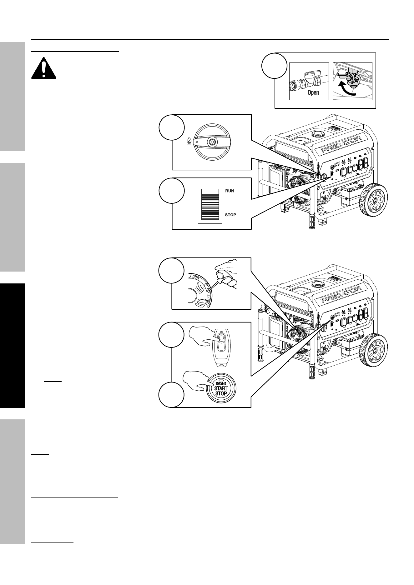
Starting the Engine – Natural Gas Operation
Before Starting the Engine
a. Inspect the generator and engine.
b. Disconnect all electrical loads from the generator.
c. Make sure the NG hose is correctly connected
to the generator and the NG source.
d. Make sure Battery is connected and charged.
1. Fully open the NG shutoff valve.
Close gasoline Fuel Valve if open.
2. Turn the Fuel Selector Switch
to the NG setting.
3. Push the Engine / Battery
Switch to the RUN position.
Select a starting method:
4. Manual Start: Grip the Starter
Handle of the Engine loosely
and pull it slowly several times
to allow gasoline to flow into the
Engine’s carburetor. Then pull
the Starter Handle gently until
resistance is felt. Allow Cable to
retract fully and then pull it quickly.
Repeat until the Engine starts. Do
not let the Starter Handle snap back
against the housing. Hold it as it
recoils so it doesn’t hit the housing.
5. Remote Start: Slowly press and
release the 2x Button on the
Stop / Start Remote Control twice.
Note: If a CO shutoff event has
occurred the remote start capability
will be disabled until the Generator
Engine has been restarted by
another method.
6. Electric Start: Slowly press
and release the Engine
Start / Stop Switch twice.
Note: The Engine is equipped with an auto-choke system and a safety solenoid valve for NG operation which
both require the battery to be charged to operate. If battery is dead, use the mechanical choke override
located above the carburetor to manually choke and unchoke the Engine. Start the Engine manually using
gasoline, then switch to NG after Engine is started. Refer to Switching Fuel Sources on page 25.
If engine does not start:
• Check engine oil level.
Engine will not start with low or no engine oil.
• Check spark arrestor cleanliness.
Engine will not start if spark arrestor is clogged.
IMPORTANT: Allow the Engine to run at no load for five minutes after each start-up so that the Engine can stabilize.
2
3
NG
1
4
5
6
2x
OFF
2x
2x

Page 25
For technical questions, please call 1-800-444-3353.
71386
SAFETYOPERATIONMAINTENANCE SETUP
Switching Fuel Sources
Fire and explosion hazard. DO NOT add gasoline to the fuel tank or connect a LPG/Propane Hose
or Natural Gas hose to the generator while the generator is in operation.
The fuel source can be switched while the Engine is running if a propane tank or
natural gas source is connected to the Generator BEFORE operation.
Switching from Gasoline to LPG / Propane or Natural Gas
1. IMPORTANT: Disconnect all electrical loads from the Generator
before switching from one fuel type to another.
2. Fully open the valve on the LPG / Propane tank or the Natural Gas shutoff valve.
3. Close the gasoline Fuel Valve on the Engine.
4. Turn the Fuel Selector Switch to the PROPANE or NG setting.
Note: When switching from gasoline to LPG / Propane or Natural Gas operation the Engine
may run rough for a few seconds while it purges gasoline in the carburetor. If the Engine
stops when switching fuel sources, the unit may be restarted using either fuel source.
Switching from LPG / Propane or Natural Gas to Gasoline
1. IMPORTANT: Disconnect all electrical loads from the Generator
before switching from one fuel type to another.
2. Open the gasoline Fuel Valve on the Engine.
3. Turn the Fuel Selector Switch to the GAS setting.
4. Turn the LPG / Propane tank valve or the Natural Gas shutoff valve to the fully closed position.
Break-in Period
a. Breaking-in the Engine will help to ensure proper equipment and Engine operation.
b. The break-in period will last about 30 hours of use.
DO NOT exceed 75% of the Generator’s running wattage during this period.
• Change the engine oil after this period.
Under normal operating conditions subsequent maintenance follows
the schedule explained in the MAINTENANCE section.
CARBON MONOXIDE SHUTOFFCARBON MONOXIDE SHUTOFF
DANGER! TO PREVENT SERIOUS INJURY AND DEATH FROM CARBON MONOXIDE INHALATION:
The Carbon Monoxide sensor is an additional layer of protection only.
DO NOT USE THE GENERATOR INDOORS OR IN ANY ENCLOSED SPACE OR IN ANY OTHER
AREA OR SITUATION THAT WILL ALLOW CARBON MONOXIDE TO ACCUMULATE.
• FLASHING RED LIGHT:
Dangerous levels of carbon monoxide gas
have built up. Leave immediately until
area has aired out. Move Generator to
well-ventilated area before operation.
• FLASHING YELLOW LIGHT:
Carbon monoxide sensor malfunction.
Sensor needs service. Call 1-800-444-3353 as
soon as possible. Do not use the Generator until
the sensor is working properly.
NOTE: Yellow light flashes once
after starting to indicate passing self-
check and is functioning normally.
The Carbon Monoxide sensor must only be serviced by a qualified technician to restore it to
original settings. Do not modify or tamper with the Carbon Monoxide sensor. Not following these
instructions can result in death or serious injury due to Carbon Monoxide sensor malfunction.
Page 26
For technical questions, please call 1-800-444-3353.
71386
SAFETY OPERATION MAINTENANCESETUP
Connecting Electrical Loads to the Generator
Calculate Power Draw
Power draw can be calculated by multiplying volts and amps. The resulting number is wattage.
• The total combined load through the outlets on the Generator must not exceed the running power of
the unit. Never exceed the running wattage for the Generator or any outlet amperage rating.
• Refer to appliance/tool owner’s manuals to determine the wattage of electrical load devices.
• Long power cords and extension cords draw additional power. Keep cord length at a minimum.
WARNING! Never exceed the rated capacity for this Generator, as serious damage to the Generator and/or
appliances, tools, and equipment could result from an overload. Starting and running wattage requirements should
always be calculated when matching this Generator’s wattage capacity to the appliance, tool, or equipment.
NOTICE: Starting and running wattages vary depending on fuel used to operate Generator. Refer to chart:
Fuel Starting Watts Running Watts
Gasoline 13,000 Maximum 10,000
LPG / Propane 12,000 Maximum 9100
Natural Gas 10,000 Maximum 7800
Wattage Estimates
Refer to your device documentation for start-up and running wattage requirements.
Check nameplate wattages on all loads before connecting to Generator.
Plug the power cord of the 120 / 240 volt appliance/tool into the appropriate Outlet
on the Generator. Plug in appliances from largest to smallest load.
a. Connect the items that require the most wattage first.
b. Connect “inductive” load appliances, tools, and equipment next. Inductive
loads are small hand tools and some small appliances.
c. Connect any lights next.
d. Voltage sensitive appliances, tools, and equipment should be the last to be connected to the Generator.
Plug voltage sensitive items such as TVs, DVD players, microwaves, and cordless telephones into a
UL
®
Listed voltage surge protector (not included). Then, connect the surge protector into the Generator.
IMPORTANT! Failure to connect and operate appliances, tools, and equipment in this sequence can cause
damage to the Generator, appliances, tools, and equipment and will void the Warranty of this Generator.
Note: Do not allow the Generator to completely run out of fuel with devices attached.
A Generator’s output may sharply spike as it runs out of fuel, causing damage to attached devices.
Low Oil Indicator
1. If the Engine oil level is too low, the LOW OIL ALARM light turns on and the Engine will automatically shut off.
2. The Engine cannot be restarted until the proper amount of oil has been added. Add the appropriate
type of oil until the oil level is at the proper level. SAE 10W-30 oil is recommended for general use.
NOTICE: Do not run the engine with too little oil. Engine will shut off if engine oil level is too low.
Automatic Idle Down Switch
1. Turn the Automatic Idle Switch ON to limit noise and fuel consumption for lighter
generator loads. Engine speed (and frequency) are reduced when no load is detected.
Engine runs at full speed (and frequency) when load above 75 W is applied.
Note: Turn Automatic Idle Switch OFF when connected load is less than 300 W.
2. Turn the Automatic Idle Switch OFF to operate Engine at full speed:
a. when starting b. when a heavy load is applied
Evenly distributed
over outlets:
IF ANY CIRCUIT BREAKERS TRIP CHECK THE FOLLOWING:
3. Make sure that ALL circuit breakers are reset
before starting the Generator again.
4. Adjust the plugs so the loads are
shared across outlet circuits.
To achieve rated output from the Generator,
distribute loads over outlets.
Plug Load In
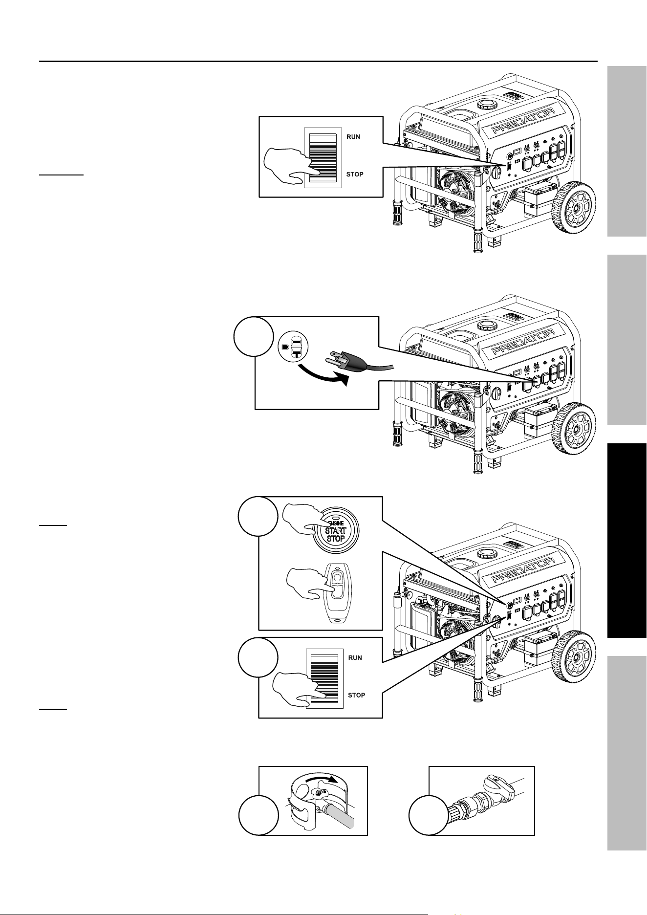
Page 27
For technical questions, please call 1-800-444-3353.
71386
SAFETYOPERATIONMAINTENANCE SETUP
Stopping the Engine
To stop the Engine in an emergency,
push the Engine / Battery Switch to STOP.
NOTICE: Generator shutoff under
load may damage the Generator
and attached equipment.
Under normal conditions, use the following procedure to shut off the Generator:
1. Turn all electrical load
devices off and unplug them
from the Generator.
2. Slowly press and release the
Engine Start/Stop Switch. Or
slowly press and release the OFF
button on the Stop / Start Remote
Control. Turn the Fuel Selector
Switch to the STORAGE position.
Note: When the Generator is turned
OFF using the Stop / Start Switch or
Remote Control, the Generator enters
standby mode and can be restarted
remotely using procedures indicated in
starting section. If Generator is not
started within 12 hours the Controller
shuts down completely to save the
battery. Push the Engine / Battery
Switch to STOP then RUN to reactivate
standby mode.
3. Push the Engine / Battery
Switch to the STOP position.
Note: Turn the Engine/Battery Switch
off when the Generator is not in
use to prevent draining the Battery.
4. If operating on LPG / Propane, turn
the propane tank valve to the fully
closed position.
5. If operating on Natural Gas,
turn the NG shutoff valve
to the closed position.
EMERGENCY
SHUT OFF
Unplug Loads
1
2
2x
OFF
3
4 5
Close
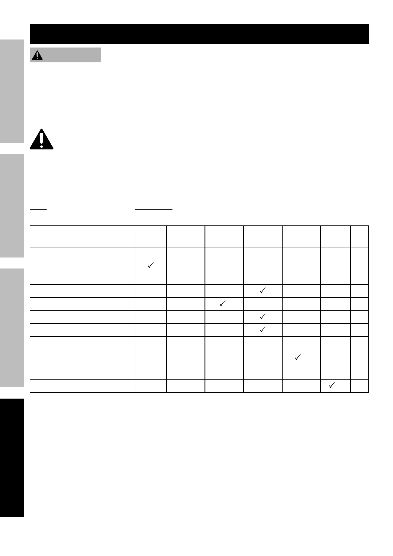
Page 28
For technical questions, please call 1-800-444-3353.
71386
SAFETY OPERATION MAINTENANCESETUP
Maintenance
WARNING
TO PREVENT SERIOUS INJURY FROM ACCIDENTAL STARTING:
Push the Engine / Battery Switch of the equipment to the "STOP" (OFF) position, wait for the engine to cool,
and disconnect the spark plug cap before performing any inspection, maintenance, or cleaning procedures.
TO PREVENT SERIOUS INJURY FROM EQUIPMENT FAILURE:
Do not use damaged equipment. If abnormal noise, vibration, or
excess smoking occurs, have the problem corrected before further use.
Follow all service instructions in this manual. The engine may fail critically if not serviced properly.
Many maintenance procedures, including any not detailed in this manual, will need to be performed
by a qualified technician for safety. If you have any doubts about your ability to safely service the
equipment or engine, have a qualified technician service the equipment instead.
Cleaning, Maintenance, and Lubrication Schedule
Note: This maintenance schedule is intended solely as a general guide. If performance decreases or if
equipment operates unusually, check systems immediately. The maintenance needs of each piece of equipment
will differ depending on factors such as duty cycle, temperature, air quality, fuel quality, and other factors.
Note: The following procedures are in addition to the regular checks and maintenance
explained as part of the regular operation of the engine and equipment.
Procedure
Before
Each Use
Monthly or
every 8 hr.
of use
Every 3 mo.
or 50 hr.
of use
Every 6 mo.
or 100 hr.
of use
Yearly or
every 300 hr.
of use
Every
2 Years
Page
1. Brush off outside of engine
2. Check engine oil level
3. Check air filter
4. Check LPG / NG hose assembly
Change engine oil
29
Clean/replace air cleaner
*
30
Check and clean spark arrestor
30
Check and clean spark plug
31
1. Check/adjust valve clearance
2. Clean fuel tank, strainer
and carburetor
3. Clean carbon build-up from
combustion chamber
**
–
Replace fuel line if necessary
**
–
*Service more frequently when used in dusty areas.
**These items should be serviced by a qualified technician.
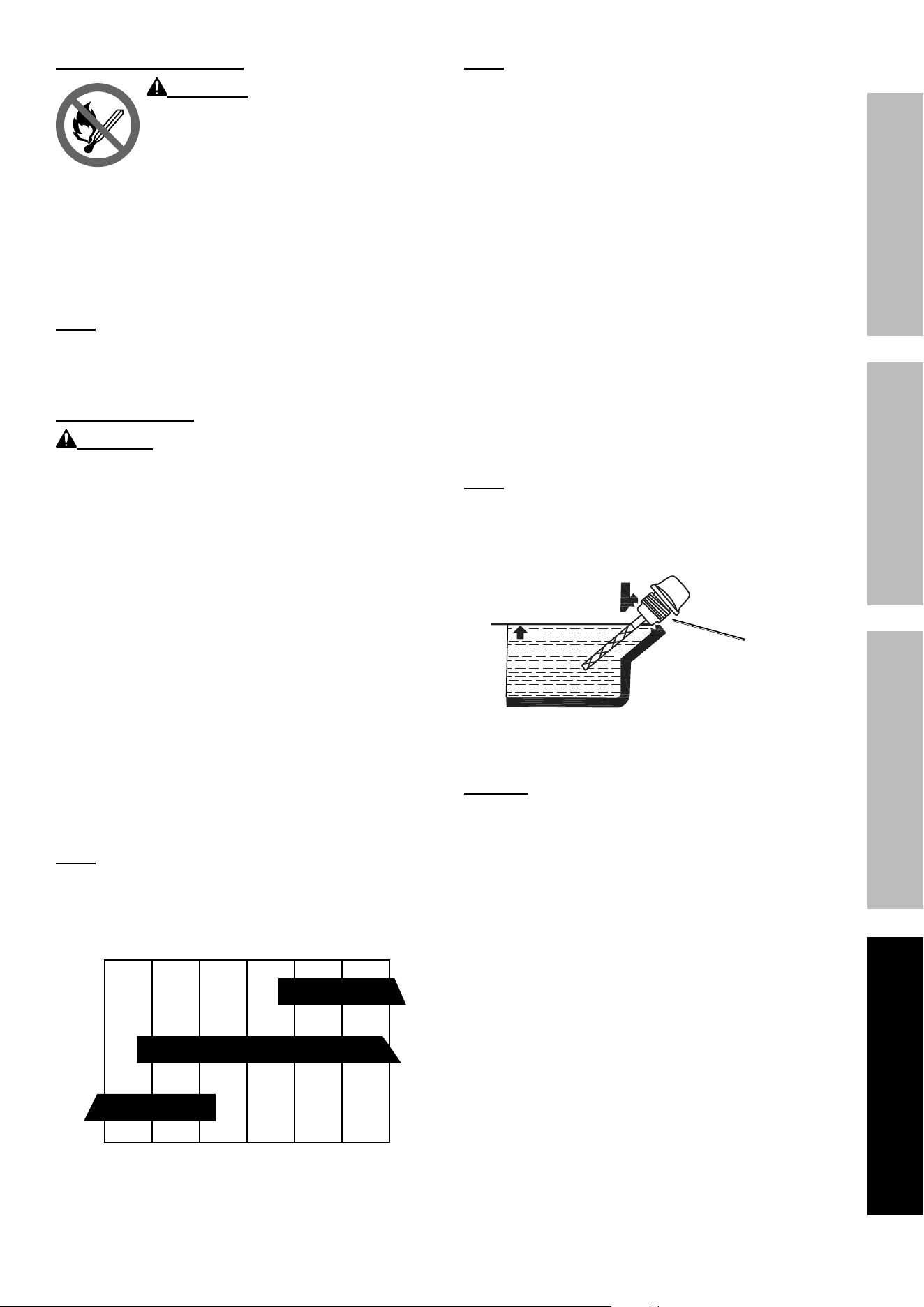
Page 29
For technical questions, please call 1-800-444-3353.
71386
SAFETYOPERATIONMAINTENANCE SETUP
Checking and Filling Fuel
WARNING! TO PREVENT SERIOUS
INJURY FROM FIRE:
Fill the fuel tank in a well-ventilated
area away from ignition sources. If the
engine is hot from use, shut the engine
off and wait for it to cool before adding
fuel. Do not smoke.
1. Clean the Fuel Cap and the area around it.
2. Unscrew and remove the Fuel Cap.
3. Remove the Strainer and remove any dirt
and debris. Then replace the Strainer.
Note: Do not use gasoline containing more than
10% ethanol (E10). Do not use E85 ethanol. Add fuel
stabilizer to the gasoline or the Warranty is VOID.
Note: Do not use gasoline that has been stored in a
metal fuel container or a dirty fuel container. It can
cause particles to enter the carburetor, affecting
engine performance and/or causing damage.
4. If needed, fill the Fuel Tank to about 1 inch under
the fill neck of the Fuel Tank with 87 octane or
higher unleaded gasoline that has been treated
with a fuel stabilizer additive. Follow fuel stabilizer
manufacturer’s recommendations for use.
5. Replace the Fuel Cap.
6. Wipe up any spilled fuel and allow excess
to evaporate before starting engine.
To prevent FIRE, do not start the engine
while the smell of fuel hangs in the air.
Engine Oil Change
CAUTION! Oil is very hot during operation and can cause burns. Wait for engine to cool before changing oil.
1. Make sure the Engine is stopped and is level.
2. Close the gasoline Fuel Valve.
3. Place an oil drain pan under the Generator
and center under the Oil Drain Plug. Remove
the Oil Drain Plug, tilt the Generator slightly
to facilitate drainage and wait for oil to
drain completely. Recycle used oil.
4. Tilt the Generator and replace the Oil
Drain Plug, then set the Generator
back down on a level surface.
5. Clean the top of the Oil Fill Cap / Dipstick
and the area around it. Remove the
Cap / Dipstick, turning it counterclockwise.
6. Add the appropriate type of oil until the oil
level is at the proper level. SAE 10W-30 oil is
recommended for general use.
Note: Do not thread the dipstick in
when checking the oil level.
The SAE Viscosity Grade chart shows other
viscosities to use in different average temperatures.
10W-30
30
5W-30
-20 0 20 40 60 80 100°F
SAE Viscosity Grades
Average outdoor temperature
Note: Make sure Generator is level when adding oil to
prevent overfilling which could cause engine damage.
7. Check the oil level. The oil level should be
up to the edge of the hole as shown.
Full Level
Oil Fill
Cap / Dipstick
8. Thread the Oil Fill Cap / Dipstick back in clockwise
and replace the Access Panel and Oil Drain Door.
NOTICE: Do not run the engine with too little oil.
Engine will not start with low or no engine oil.
Page 30
For technical questions, please call 1-800-444-3353.
71386
SAFETY OPERATION MAINTENANCESETUP
Air Filter Element Maintenance
1. Remove the Air Filter Cover and the
air filter elements and check for dirt.
Clean as described below.
2. Cleaning:
• For “paper” filter elements:
To prevent injury from dust and debris,
wear ANSI-approved safety goggles,
NIOSH-approved dust mask/respirator, and
heavy-duty work gloves. In a well-ventilated
area away from bystanders, use pressurized
air to blow dust out of the air filter.
• For foam filter elements:
Wash the element in warm water and
mild detergent several times. Rinse.
Squeeze out excess water and allow it to dry
completely. Soak the filter in lightweight oil
briefly, then squeeze out the excess oil.
3. Install the cleaned filter.
4. Secure the Air Filter Cover before use.
Spark Arrestor Maintenance
TO PREVENT SERIOUS INJURY AND FIRE: Operate only with proper spark arrestor installed.
Operation of this equipment may create sparks that can start fires around dry vegetation.
A spark arrestor may be required. The operator should contact local fire agencies for laws or
regulations relating to fire prevention requirements.
1. Allow the Generator to cool completely.
2. Remove Spark Arrestor from end of exhaust.
3. Clean the Spark Arrestor using a wire brush
(sold separately). Replace Arrestor if damaged.
4. WARNING! TO PREVENT SERIOUS INJURY
FROM ACCIDENTAL BRUSH FIRE, secure
Spark Arrestor back in place immediately
after cleaning and before further operation.
Remote Control Battery Replacement
1. Remove screw(s) and open battery compartment.
2. Remove battery and dispose of properly.
3. Insert battery in correct polarity, close
compartment and replace screw(s).
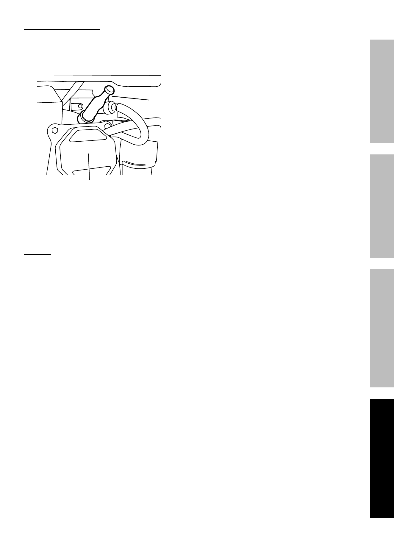
Page 31
For technical questions, please call 1-800-444-3353.
71386
SAFETYOPERATIONMAINTENANCE SETUP
Spark Plug Maintenance
1. Disconnect Spark Plug Cap from end of plug.
Clean out debris from around Spark Plug.
2. Use a spark plug wrench to remove the Spark Plug.
Cylinder
Assembly
Spark
Plug Cap
3. Inspect the Spark Plug:
If the electrode is oily, clean it using a clean, dry rag.
If the electrode has deposits on it, polish it using
emery paper. If the white insulator is cracked or
chipped, the Spark Plug needs to be replaced.
NOTICE: Use only F7RTJC type spark
plug or equivalent. Using an incorrect
spark plug may damage the engine.
4. When installing a new spark plug,
adjust the plug’s gap to the specification on the
Specifications chart. Do not pry against the
electrode — the spark plug can be damaged.
5. Apply anti-seize material to Spark Plug threads.
Install the new spark plug or
the cleaned spark plug into the engine.
• Gasket-style:
Finger-tighten until the gasket
contacts the cylinder head,
then tighten about 1/2-2/3 turn more.
• Non-gasket-style:
Finger-tighten until the plug
contacts the cylinder head,
then tighten about 1/16 turn more.
NOTICE: Tighten the spark plug properly.
If loose, the spark plug will cause the
engine to overheat.
If overtightened, the threads in the
engine block will be damaged.
6. Apply dielectric spark plug boot protector
(not included) to the end of the spark plug
and reattach the cap securely.
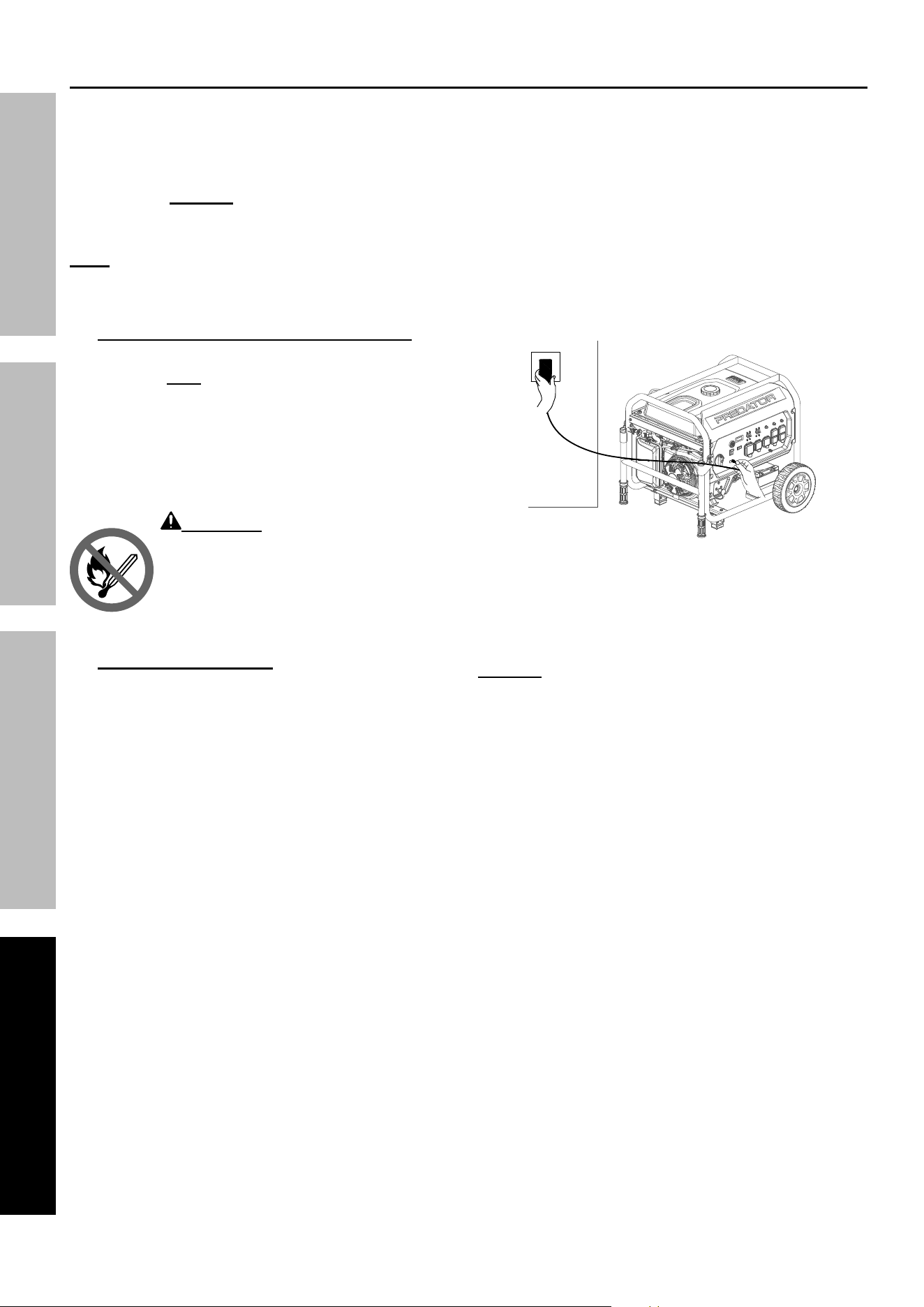
Page 32
For technical questions, please call 1-800-444-3353.
71386
SAFETY OPERATION MAINTENANCESETUP
Storage
When the equipment is to remain idle for longer than
20 days, prepare the engine for storage as follows:
1. CLEANING:
Wait for engine to cool, then clean engine with
dry cloth. NOTICE: Do not clean using water.
The water will gradually enter the
engine and cause damage.
Note: Keep the LPG / NG Inlet covered
during cleaning and storage.
2. FUEL:
Gasoline Treatment/Draining the Fuel Tank
To protect the Fuel Tank during storage, fill the
Tank with fresh gasoline that has been treated
with a fuel stabilizer additive. Follow fuel stabilizer
manufacturer’s recommendations for use. Refer
to Checking and Filling Fuel on page 18.
Aged gasoline that has not been treated with
stabilizer ahead of time must be safely drained
away and not run through the Engine.
WARNING! TO PREVENT SERIOUS
INJURY FROM FIRE:
Fill tank in a well-ventilated area away
from ignition sources. If the engine
is hot from use, shut the engine off and
wait for it to cool before adding fuel.
Do not smoke.
Draining the Carburetor
Close the gasoline Fuel Valve and turn the Fuel
Selector Switch to the STORAGE position.
Place an appropriate container under the
Carburetor. Carefully loosen and remove the
Drain Bolt from the bottom of the Carburetor
Bowl and allow the fuel to drain completely.
Replace the Drain Bolt after draining.
WARNING! To prevent serious injury
and fire, close the gasoline Fuel Valve
before draining the Carburetor.
3. LUBRICATION:
a. Change engine oil.
b. Clean out area around spark plug.
Remove spark plug and pour one tablespoon of
engine oil into cylinder through spark plug hole.
c. Replace spark plug, but leave
spark plug cap disconnected.
d. Pull Starter Handle to distribute oil in cylinder.
Stop after one or two revolutions when you
feel the piston start the compression stroke
(when you start to feel resistance).
4. 12 VDC BATTERY:
When Generator is not in use or
will be stored for extended periods,
use the Battery Charger / Maintainer
provided to maintain the Battery:
a. Plug the Charger / Maintainer power cord into
the Battery Charging Port on the Generator.
b. Plug the Charger / Maintainer
into an electrical outlet.
c. Disconnect the Charger / Maintainer
before using the Generator.
5. STORAGE AREA:
Cover and store in a dry, level, well-ventilated
area out of reach of children. Storage area should
also be away from ignition sources, such as
water heaters, clothes dryers, and furnaces.
NOTICE: During extended storage periods the
Engine must be started every 3 months and allowed
to run for 15 – 20 minutes or the Warranty is VOID.
6. AFTER STORAGE:
Before starting the Engine after storage, keep in
mind that untreated gasoline will deteriorate quickly.
Drain the Fuel Tank and change to fresh fuel if
untreated gasoline has been sitting for a month,
if treated gasoline has been sitting beyond the
fuel stabilizer’s recommended time period,
or if the Engine does not start.
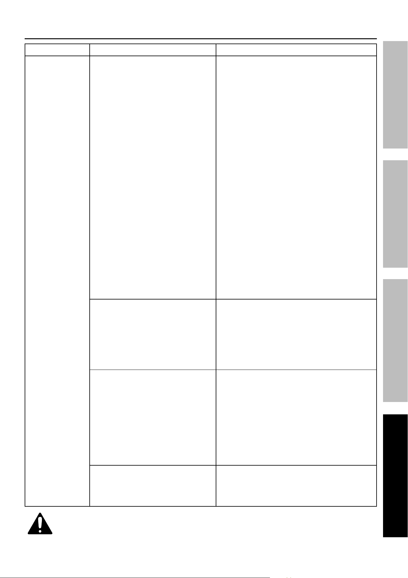
Page 33
For technical questions, please call 1-800-444-3353.
71386
SAFETYOPERATIONMAINTENANCE SETUP
Troubleshooting
Problem Possible Causes Probable Solutions
Engine will not start FUEL RELATED:
1. No fuel in tank or fuel valve closed.
2. No fuel flow.
3. Battery depleted – must be charged and
connected to start with LPG or NG fuel.
4. Gasoline with more than 10% ethanol
used. (E15, E20, E85, etc.)
5. Low quality or deteriorated, old gasoline.
6. Carburetor not primed.
7. Dirty fuel passageways.
8. Carburetor needle stuck.
Fuel can be smelled in the air.
9. Too much fuel in chamber. This can be
caused by the carburetor needle sticking.
10. Clogged Fuel Filter.
11. LPG / Propane tank is too small or empty.
12. Improper Natural Gas rating
(pressure and flow).
FUEL RELATED:
1. Fill fuel tank with fresh 87+ octane stabilizer-treated
unleaded gasoline and open fuel valve.
Do not use gasoline with more than
10% ethanol (E15, E20, E85, etc.).
2. Move Fuel Selector Switch to desired fuel
type. For LPG / NG fuel, make sure LPG tank
valve or NG shutoff valve is fully open.
3. Start Engine manually with gasoline, then switch
to LPG or NG fuel while Engine is running.
4. Clean out ethanol rich gasoline from fuel system.
Replace components damaged by ethanol. Use fresh
87+ octane stabilizer-treated unleaded gasoline only.
Do not use gasoline with more than
10% ethanol (E15, E20, E85, etc.).
5. Use fresh 87+ octane stabilizer-treated
unleaded gasoline.
Do not use gasoline with more than
10% ethanol (E15, E20, E85, etc.).
6. Pull on Starter Handle to prime.
7. Clean out passageways using fuel additive.
Heavy deposits may require further cleaning.
8. Gently tap side of carburetor float
chamber with screwdriver handle.
9. Turn Choke to RUN position. Remove spark plug and
pull the start handle several times to air out the chamber.
Reinstall spark plug and set Choke to START position.
10. Replace Fuel Filter.
11. Use 40 lb. tank or larger; make sure tank is full.
12. Make sure the NG supply system can meet the
requirements indicated in the Specification Section .
IGNITION (SPARK) RELATED:
1. Engine/Battery Switch at STOP position.
2. Spark plug cap not connected securely.
3. Spark plug electrode wet or dirty.
4. Incorrect spark plug gap.
5. Spark plug cap broken.
6. Incorrect spark timing or
faulty ignition system.
IGNITION (SPARK) RELATED:
1. Push Engine/Battery Switch to RUN position.
2. Connect spark plug cap properly.
3. Clean spark plug.
4. Correct spark plug gap.
5. Replace spark plug cap.
6. Have qualified technician diagnose/
repair ignition system.
COMPRESSION RELATED:
1. Cylinder not lubricated.
Problem after long storage periods.
2. Loose or broken spark plug.
(Hissing noise will occur
when trying to start.)
3. Loose cylinder head or damaged
head gasket. (Hissing noise will
occur when trying to start.)
4. Engine valves or tappets
mis-adjusted or stuck.
ENGINE OIL RELATED:
1. Low engine oil.
2. Engine mounted on slope,
triggering low oil shutdown.
COMPRESSION RELATED:
1. Pour tablespoon of oil into spark plug hole. Crank
engine a few times and try to start again.
2. Tighten spark plug.
If that does not work, replace spark plug.
If problem persists, may have head
gasket problem – see #3.
3. Tighten head.
If that does not remedy problem, replace head gasket.
4. Have qualified technician adjust/
repair valves and tappets.
ENGINE OIL RELATED:
1. Fill engine oil to proper level. Check engine
oil before EVERY use.
2. Operate engine on level surface. Check engine oil level.
Follow all safety precautions whenever diagnosing or servicing the generator or engine.

Page 34
For technical questions, please call 1-800-444-3353.
71386
SAFETY OPERATION MAINTENANCESETUP
Problem Possible Causes Probable Solutions
Engine will not
start (continued)
SPARK ARRESTOR RELATED:
Spark Arrestor clogged with soot.
SPARK ARRESTOR RELATED:
Clean and replace Spark Arrestor.
ELECTRIC OR REMOTE START RELATED:
1. No battery or defective battery installed.
2. Engine Start/Stop Switch flashes
red – Battery is low.
3. Electric start fuse (5 A) is blown.
4. Stop/Start Remote Control is
not paired with Generator.
5. Generator not picking up Stop/Start
Remote Control signal consistently.
6. Engine not restarting remotely
after CO shutdown event.
ELECTRIC OR REMOTE START RELATED:
1. Install a new battery.
2. Charge battery with Battery Charger / Maintainer or
start Generator manually and allow to run for 5 hours.
3. Replace fuse with similar size fuse.
4. Pair Remote Control to Generator. Refer to page 21.
5. Replace the Remote Control battery; press on Remote
Button longer; stay within operational range of Remote.
6. After a CO shutdown event, the remote start
capability will be disabled until the Engine
has been first restarted non-remotely.
Engine misfires 1. Spark plug cap loose.
2. Incorrect spark plug gap or
damaged spark plug.
3. Defective spark plug cap.
4. Old or low quality gasoline.
5. Incorrect compression.
1. Check cap and wire connections.
2. Re-gap or replace spark plug.
3. Replace spark plug cap.
4. Use only fresh 87+ octane stabilizer-treated
unleaded gasoline.
Do not use gasoline with more than
10% ethanol (E15, E20, E85, etc.).
5. Diagnose and repair compression. Use Engine will
not start: COMPRESSION RELATED section.
Engine stops suddenly 1. Carbon Monoxide level high. Red light
on Carbon Monoxide Sensor illuminates.
2. CO Sensor Alarm flashes yellow
continually shortly after starting.
3. CO Sensor Alarm flashes yellow
continually after longer period of operation.
4. Low oil shutdown.
5. Fuel tank empty or full of impure or low
quality gasoline.
6. Defective fuel tank cap creating
vacuum, preventing fuel flow.
7. Faulty magneto.
8. Disconnected or improperly
connected spark plug cap.
9. Unintentional shutdown signal sent
from Stop/Start Remote Control.
10. If using Natural Gas: inadequate
fuel pressure / flow.
11. If using LPG / Propane: LPG tank
empty or LPG tank too small.
1. Leave area immediately and allow area to ventilate
thoroughly. Only operate generator outside.
2. Carbon monoxide sensor malfunction.
Sensor needs service. Call 1-800-444-3353 as
soon as possible. Do not use the Generator
until the sensor is working properly.
3. Make sure to operate Generator within
rated ambient temperature; maintain
minimum 5 ft. clearance from all sides.
4. Fill engine oil to proper level. Check
engine oil before EVERY use.
5. Fill fuel tank with fresh 87+ octane stabilizer treated
unleaded gasoline.
Do not use gasoline with more than 10%
ethanol (E15, E20, E85, etc.).
6. Test / replace fuel tank cap.
7. Have qualified technician service magneto.
8. Secure spark plug cap.
9. Store the Remote Control in a safe
location and away from children.
10. Ensure NG fuel pressure and flow meet Generator
requirements. Refer to Specifications on page 3.
11. Replace empty LPG tank with full tank. Replace
small LPG tank with correct tank size. Refer
to Specifications on page 3.
Engine stops when
under heavy load
1. Dirty air filter
2. Engine running cold.
1. Clean or replace element.
2. Allow engine to warm up prior to operating equipment.
Follow all safety precautions whenever diagnosing or servicing the generator or engine.
Page 35
For technical questions, please call 1-800-444-3353.
71386
SAFETYOPERATIONMAINTENANCE SETUP
Problem Possible Causes Probable Solutions
Engine knocks 1. Old or low quality gasoline.
2. Engine overloaded.
3. Incorrect spark timing, deposit
buildup, worn engine, or other
mechanical problems.
1. Fill fuel tank with fresh 87+ octane stabilizer-treated
unleaded gasoline.
Do not use gasoline with more than
10% ethanol (E15, E20, E85, etc.).
2. Do not exceed equipment’s load rating.
3. Have qualified technician diagnose and service engine.
Engine backfires 1. Impure or low quality gasoline.
2. Engine too cold.
3. Intake valve stuck or overheated engine.
4. Incorrect timing.
1. Fill fuel tank with fresh 87+ octane stabilizer-treated
unleaded gasoline.
Do not use gasoline with more than
10% ethanol (E15, E20, E85, etc.).
2. Use cold weather fuel and oil additives
to prevent backfiring.
3. Have qualified technician diagnose and service engine.
4. Check engine timing.
Attached device
doesn’t have power
1. Device not plugged in properly.
2. Circuit Breaker tripped.
3. GFCI activated.
4. Product needs service.
1. Turn off and unplug the device,
then plug it back in again and turn on.
2. Turn off and unplug device, reset Circuit
Breaker, plug in device and turn on.
3. Turn off and unplug device. Test GFCI
receptacle. If functioning properly reset
GFCI, plug in device and turn on.
4. Have product repaired.
Attached device
begins to operate
abnormally
1. Problem with device.
2. Rated load capacity exceeded.
1. Immediately unplug device.
Have device repaired by a qualified
technician, or replace device.
2. Lower the number of items plugged into the
Generator to stay within the rated capacity,
or use a more powerful generator.
Follow all safety precautions whenever diagnosing or servicing the generator or engine.

Page 36
For technical questions, please call 1-800-444-3353.
71386
SAFETY OPERATION MAINTENANCESETUP
PLEASE READ THE FOLLOWING CAREFULLY
THE MANUFACTURER AND/OR DISTRIBUTOR HAS PROVIDED THE PARTS LISTS AND ASSEMBLY
DIAGRAMS IN THIS MANUAL AS A REFERENCE TOOL ONLY. NEITHER THE MANUFACTURER OR
DISTRIBUTOR MAKES ANY REPRESENTATION OR WARRANTY OF ANY KIND TO THE BUYER THAT HE
OR SHE IS QUALIFIED TO MAKE ANY REPAIRS TO THE PRODUCT, OR THAT HE OR SHE IS QUALIFIED
TO REPLACE ANY PARTS OF THE PRODUCT. IN FACT, THE MANUFACTURER AND/OR DISTRIBUTOR
EXPRESSLY STATES THAT ALL REPAIRS AND PARTS REPLACEMENTS SHOULD BE UNDERTAKEN BY
CERTIFIED AND LICENSED TECHNICIANS, AND NOT BY THE BUYER. THE BUYER ASSUMES ALL RISK
AND LIABILITY ARISING OUT OF HIS OR HER REPAIRS TO THE ORIGINAL PRODUCT OR REPLACEMENT
PARTS THERETO, OR ARISING OUT OF HIS OR HER INSTALLATION OF REPLACEMENT PARTS THERETO.
Record Product’s Serial Number Here:
Note: If product has no serial number, record month and year of purchase instead.
Note: Some parts are listed and shown for illustration purposes only, and are not available
individually as replacement parts. Specify UPC 193175546814 when ordering parts.
Page 37
For technical questions, please call 1-800-444-3353.
71386
SAFETYOPERATIONMAINTENANCE SETUP
Part Description Qty
1 Hex Socket Flange Face Bolt - Small Series 4
2 Cylinder Head Cover Subassembly 1
3 Cylinder Head Cover Gasket 1
4 Stop Detent 1
5 Breather Tube 1
6 Pipe Clamp 2
7 Inner Cylinder Head Cover 1
8 Gasket 1
9 Valve Rocker Subassembly 2
10 Rocker Shaft Subassembly 2
11 Hex Socket Flange Face Bolt - Small Series 3
12 Cylinder Head Cover Pin Limit Plate 1
13 Valve Rotator 2
14 Valve Lock Clamp 4
15 Valve Spring Seat 2
16 Valve Spring 2
17 Seal Guide 1
18 Cylinder Head Bolt 4
19 Cylinder Head Subassembly 1
20 Exhaust Pipe 1
21 Type 1 Nut 2
22 Muffler Gasket 1
23 Stud Bolt 2
24 Spark Plug 1
25 Cylinder Head Gasket 1
26 Position Pin - Type A 2
27 Valve Set 1
28 Valve Lifter Subassembly 2
29 Valve Tappet 2
30 Piston Ring Assembly 1
31 Piston 1
32 Connecting Rod 1
33 Piston Pin 1
34 Piston Pin Clip 2
35 Temperature Sensor 1
36 Hex Socket Flange Face Bolt - Small Series 1
37 Cylinder Body Shroud 1
38 Flat Washer 2
39 Hex Socket Flange Face Bolt - Small Series 2
40 Crankcase Air Deflector 1
41 Oil Seal 1
42 Hex Socket Flange Face Bolt - Small Series 2
43 Starting Motor Assembly 1
44 Drain Plug Bolt 2
45 Wire Clip 3
46 Rubber Plug 1
47 Crankcase Subassembly 1
48 Deep Groove Ball Bearing - P6 1
49 Crankshaft Assembly 1
50 Balancing Shaft 1
51 Camshaft Assembly 1
52 Engine Oil Sensor 1
53 Hex Socket Flange Face Bolt - Small Series 2
54 Flange Nut 1
55 Position Pin - Type A 2
56 Crankcase Gasket 1
57 Deep Groove Ball Bearing - P6 1
Part Description Qty
58 Deep Groove Ball Bearing - P53 1
59 Oil Dipstick Subassembly 1
60 Crankcase Cover 1
61 Hex Socket Flange Face Bolt - Small Series 9
62 Oil Seal 1
63 Pipe Clamp 2
64 Shroud 1
65 Hex Socket Flange Face Bolt - Small Series 5
66 Recoil Starter Assembly 1
67 Ignition Coil 1
68 Hex Socket Flange Face Bolt - Small Series 2
69 Flywheel Nut 1
70 Starter Pulley 1
71 Impeller 1
72 Hex Socket Flange Face Bolt - Small Series 1
73 Charge Coil Clamp 1
74 Flywheel Subassembly 1
75 Hex Socket Flange Face Bolt - Small Series 4
76 Charge Coil Subassembly 1
77 Throttle Bottom Plate 1
78 Hex Socket Flange Face Bolt - Small Series 3
79 Stud Bolt 2
80 Inlet Gasket 1
81 Carburetor Insulator Plate 1
82 Carburetor Seal Gasket 1
83 Carburetor Assembly 1
84 Air Cleaner Seal Gasket 1
85 Pipe Clamp 1
86 Rubber Jacket 1
87 Fuel Tube 1
88 Rubber Jacket 1
89 Hex Socket Flange Face Bolt - Small Series 1
90 Air Cleaner Bracket 1
91 Air Cleaner Assembly 1
92 Flange Nut 2
93 Air Cleaner Element 1
94 Air Duct 1
95 Small Spiral Narrow Band Collar - Type A 1
96 Muffler Gasket 1
97 Hex Socket Flange Face Bolt - Small Series 2
98 Muffler Assembly 1
99 Hex Socket Flange Face Bolt - Small Series 2
100 Muffler Bracket 1
101 Hex Socket Flange Face Bolt - Small Series 2
102 Motor Shroud 1
103 Hex Socket Flange Face Bolt - Small Series 1
104 Stator Nut 2
105 Flat Washer 2
106 Standard Spring Washer 2
107 Motor Assembly 1
108 Carbon Brush Subassembly 1
109 Hex Socket Flange Face Bolt - Small Series 1
110 Terminal Block 1
111 Hex Socket Flange Face Bolt - Small Series 2
112 Stopper 1
113 Motor Support 1
114 Hex Socket Flange Face Bolt - Small Series 1
Parts List and Diagram
Parts List
Page 38
For technical questions, please call 1-800-444-3353.
71386
SAFETY OPERATION MAINTENANCESETUP
Parts List (continued)
Part Description Qty
115 Flat Washer 1
116 Stator Bolt 4
117 Rotor Bolt 1
118 Stator Bolt 2
119 Voltage Regulator 1
120 Hex Socket Flange Face Bolt - Small Series 2
121 Motor Tail Cover 1
122 Hex Socket Flange Face Bolt - Small Series 2
123 Band 2
124 Hex Socket Flange Face Bolt - Small Series 2
125 Grounding 1
126 External Teeth Serrated Lock Washer 1
127 Fuel Tank 1
128 Fuel Tank Rubber Sleeve 4
129 Bushing 4
130 Flat Washer 4
131 Hex Socket Flange Face Bolt - Big Series 4
132 Cross Recessed Countersunk Head Screw 2
133 Oil Leveler Assembly 1
134 Fuel Tank Cap 1
135 Fuel Strainer 1
136 One Way Valve 1
137 Carbon Canister Hose 1
138 Flange Nut 2
139 Bracket 1
140 Carbon Canister 1
141 Air Cleaner Hose 1
142 Pipe Clamp 1
143 Protective Rubber Sleeve 2
144 Fuel Cock Assembly 1
145 Pipe Clamp 1
146 Fuel Tube 1
147 Hex Socket Flange Face Bolt - Big Series 4
148 Crosspiece Subassembly 1
149 Wire Clip 2
150 Engine Frame Assembly 1
151 Buffering Pad Support 2
152 Flange Nut - Fin Thread 4
153 Engine Frame Cushion 4
154 Flange Nut 4
155 Bracket 1
156 Hex Socket Flange Face Bolt - Big Series 5
157 Engine Frame Shock Absorption Seat 4
158 Flange Nut 2
159 Hex Socket Flange Face Bolt - Big Series 1
160 Battery Clamp 2
161 Battery 1
162 Thermal Baffle 2
163 Thermal Baffle 1
164 Anode Wire 1
165 Hex Socket Flange Face Bolt - Big Series 1
166 Cathode Wire 1
167 Ground Wire 1
168 Engine Frame Shock Absorption Seat 2
169 Engine Frame Shock Absorption Support 2
170 Flange Nut 4
Part Description Qty
171 Hex Socket Flange Face Bolt - Small Series 2
172 Front Wheel Shaft 2
173 Flat Washer 6
174 Wheel 2
175 Cotter Pin 2
176 Handle Sleeve 2
177 Handle Tube Assembly 1
178 Handle Release Pin 1
179 Nut 1
180 Hex Step Bolt 2
181 Type 2 All Metal Hex Lock Nut w/Flange 2
182 End Plug 2
183 Pin Shaft 1
184 Strap 1
185 Flange Nut 4
186 Fuel Cock Assembly 1
187 Small Spiral Narrow Band Collar - Type A 3
188 Air Duct 1
189 Gas Pressure Relief Valve 1
190 Cross-Recessed Pan Head Screw 3
191 Carbon Monoxide Alarm 1
192 Screw 2
193 Flange Nut 6
194 Front Panel 1
195 Knob 1
196 Cross-Recessed Pan Head Screw 1
197 Control Module 1
198 Charger Module 1
199 Hex Socket Flange Face Bolt - Big Series 5
200 Control Panel Subassembly 1
201 Cross-Recessed Pan Head Tapping Screw 4
202 Switch Subassembly 1
203 Starting Switch 1
204 Timer 1
205 Double-Pole Circuit Breaker 1
206 Double-Pole Circuit Breaker 1
207 Overcurrent Protector 3
208 Power Supply Socket Subassembly 2
209 Water Proof Cover 2
210 Grounding Terminal Subassembly 1
211 Power Supply Socket Subassembly 1
212 Rain Cover Receptacle 2
213 Power Supply Socket Subassembly 1
214 Power Supply Socket Subassembly 1
215 Rain Cover Receptacle 1
216 Switch Subassembly 1
217 Oil Alarm Indicator 1
218 CO Indicator Mounting Base 1
219 CO Indicator 1
220 Remote Control Module 1
221 Pipe Clamp 2
222 Band 2
223 Battery Charger / Maintainer 1
224 Remote Control 1
225 LPG / Propane Attachment Kit 1
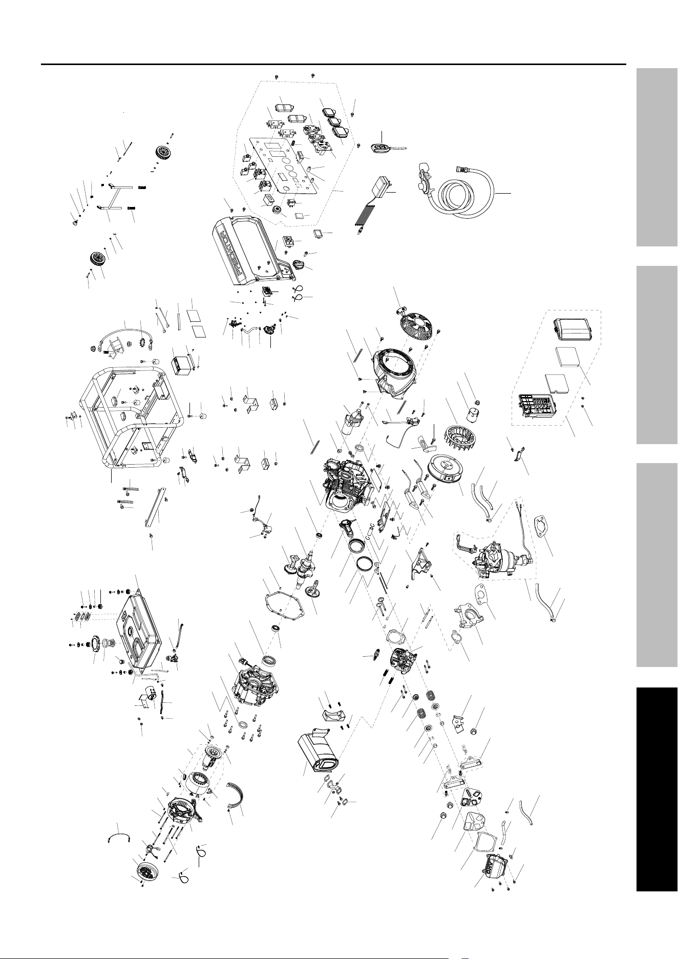
Page 39
For technical questions, please call 1-800-444-3353.
71386
SAFETYOPERATIONMAINTENANCE SETUP
Assembly Diagram
3
28
29
30
31
27
33
32
39
38
37
36
35
34
4
6
5
7
8
10
9
13
11
12
14
15
16
17
18
19
23
25
24
26
40
41
42
43
44
45
46
47
48
49
51
50
52
53
54
55
56
57
58
59
60
61
62
64
65
66
68
67
69
70
71
72
73
75
74
76
77
78
79
80
81
82
84
85
86
87
88
45
83
94
95
63
11
1
2
20
21
22
96
99
100
101
97
98
102
103
104
106
105
107
108
109
110
111
113
117
123
124
123
124
112
114
118
115
116
119
120
121
122
125
12 6
172
173
174
175
173
173
17
177
178
179
180
181
182
183
184
150
151
147
148
89
90
152
153
154
156
155
156
157
159
160
161
162
163
164
165
166
167
149
147
221
138
139
137
136
134
135
132
133
127
128
129
130
131
146
145
144
143
142
141
140
168
169
170
171
158
185
186
187
188
187
189
187
190
191
192
194
193
195
196
201
197
198
200
202
204
205
199
206
207
209
210
211
212
213
215
216
217
219
203
218
208
214
220
222
89
90
93
92
91
168
169
170
171
158
6
223
225
224

Page 40
For technical questions, please call 1-800-444-3353.
71386
SAFETY OPERATION MAINTENANCESETUP
Warranties
Limited 90 Day Warranty (Retail)
Harbor Freight Tools Co. makes every effort to assure that its products meet high quality and durability standards,
and warrants to the original purchaser that this product is free from defects in materials and workmanship for the
period of 90 days from the date of purchase. This warranty does not apply to damage due directly or indirectly,
to misuse, abuse, negligence or accidents, repairs or alterations outside our facilities, criminal activity, improper
installation, normal wear and tear, or to lack of maintenance. We shall in no event be liable for death, injuries
to persons or property, or for incidental, contingent, special or consequential damages arising from the use of
our product. Some states do not allow the exclusion or limitation of incidental or consequential damages, so
the above limitation of exclusion may not apply to you. THIS WARRANTY IS EXPRESSLY IN LIEU OF ALL
OTHER WARRANTIES, EXPRESS OR IMPLIED, INCLUDING THE WARRANTIES OF MERCHANTABILITY
AND FITNESS, EXCEPT FOR THE EMISSIONS CONTROL SYSTEM WARRANTY BELOW.
To take advantage of this warranty, the product or part must be returned to us with transportation charges prepaid.
Proof of purchase date and an explanation of the complaint must accompany the merchandise. If our
inspection verifies the defect, we will either repair or replace the product at our election or we may elect to
refund the purchase price if we cannot readily and quickly provide you with a replacement. We will return
repaired products at our expense, but if we determine there is no defect, or that the defect resulted from
causes not within the scope of our warranty, then you must bear the cost of returning the product.
This warranty gives you specific legal rights and you may also have other rights which vary from state to state.

Page 41
For technical questions, please call 1-800-444-3353.
71386
SAFETYOPERATIONMAINTENANCE SETUP
Emissions Control System Warranty
Harbor Freight Tools (HFT) is pleased to explain the emissions control system warranty on your Small Off-Road
Engine produced after January 1, 2024 (engine), in addition to the Retail Warranty above. HFT warrants that the
emissions control system on your engine is designed, built, and equipped so that it conforms to the United States
Environmental Protections Agency’s (EPA) emissions requirements in effect at the time of manufacture. HFT also
warrants that the emissions control system on your engine will be free from defects in material and workmanship for
two (2) years, provided there has been no improper maintenance, misuse, or abuse of your engine.
Your emissions control system may include parts such as the carburetor or fuel-injection system, and the ignition
system. Also included may be hoses, belts, connectors and other emissions-related assemblies.
WHAT WE WILL DO
Where a warrantable condition exists, HFT will repair or replace, at our option, any emissions-related part on
your engine if it becomes defective, malfunctions, or otherwise fails to conform with this warranty under normal use
and service during the two (2) year term of this warranty at no cost to you, including diagnosis, parts and labor. This
warranty applies to the original purchaser and any subsequent owner within the two year warranty period.
WHAT IS COVERED?
The following parts are examples of components of the emissions control system and are covered by this
two (2) year warranty. For a full list of emissions control components covered by this warranty, please see 40 CFR
§1068, Appendix I.
1. Fuel Metering System
a. Carburetor and its internal parts.
b. Fuel pump (if so equipped).
c. Cold start enrichment system.
2. Air Induction System
a. Intake pipe/manifold.
b. Air cleaner.
3. Ignition System
a. Spark plug.
b. Magneto ignition system.
4. Catalyst System (if so equipped)
a. Exhaust pipe stud.
b. Muffler.
c. Catalytic converter (if so equipped).
5. Miscellaneous Items Used in Above Systems
a. Vacuum, temperature and time sensitive valves
and switches.
b. Hoses, belts, connectors, and assemblies.
This warranty does not cover normal maintenance services or replacement of maintenance items such as filters,
oils, or spark plugs.
WHAT YOU MUST DO TO OBTAIN WARRANTY SERVICE
As the engine owner, you are responsible for the performance of the required maintenance listed in your
Owner’s Manual. HFT may deny you warranty coverage if your engine or a part has failed due to abuse (including
failure to follow the fuel use instructions contained in this manual), neglect, improper maintenance, or unapproved
modifications.
In order to obtain warranty repair or replacement, you may either (a) contact HFT product support at 1-800-444-3353
or [email protected]; or (b) bring the engine/equipment to your nearest Harbor Freight Tools retail
store. When going to the retail store or contacting product support, you must indicate the specific emissions control
part or defect that you are claiming and the date this was originally purchased. The nearest Harbor Freight Tools retail
store can be found on the internet at https://www.harborfreight.com.

Page 42
For technical questions, please call 1-800-444-3353.
71386
SAFETY OPERATION MAINTENANCESETUP

Page 43
For technical questions, please call 1-800-444-3353.
71386
SAFETYOPERATIONMAINTENANCE SETUP

26677 Agoura Road • Calabasas, CA 91302 • 1-800-444-3353
