9.808-246.0 - J (10/30/24)
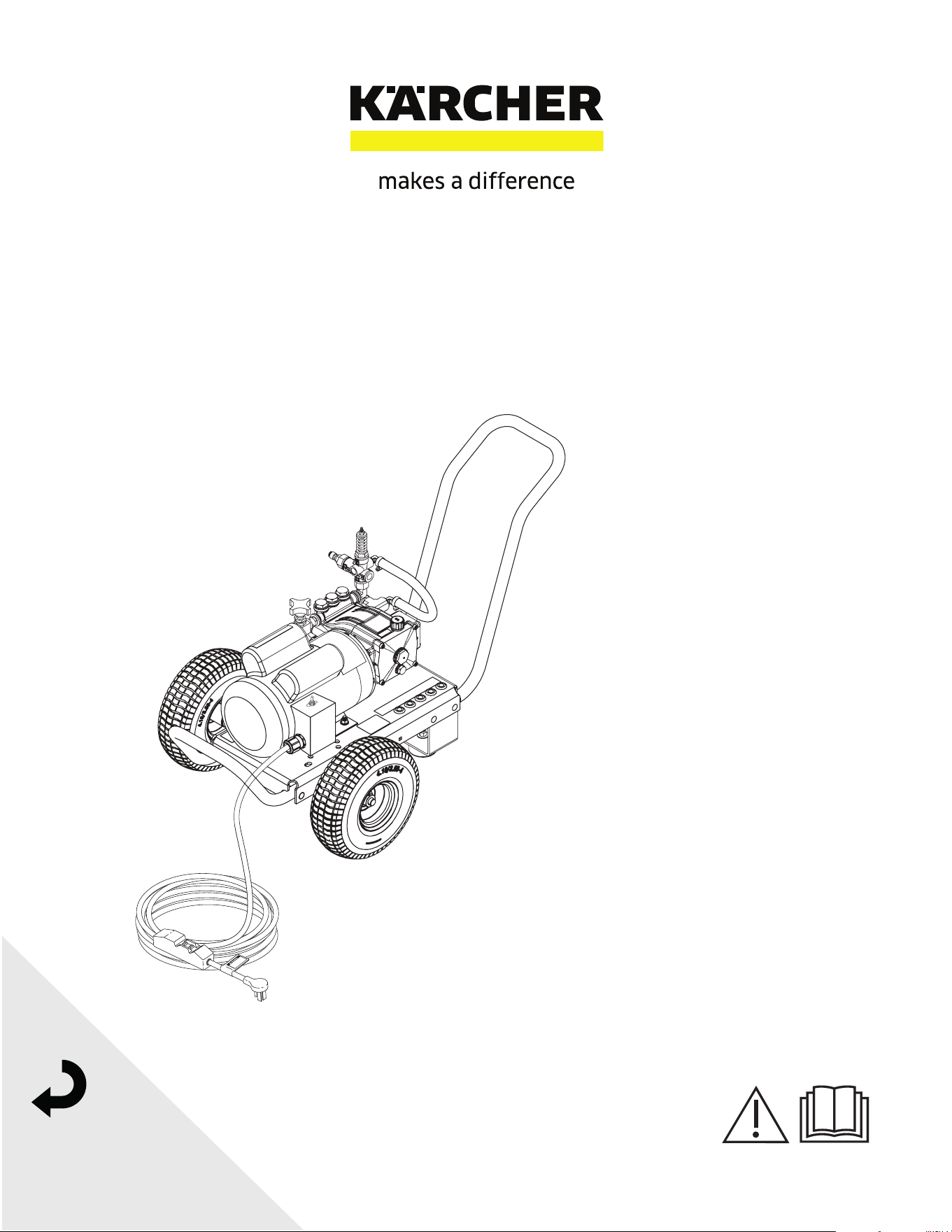
High pressure cleaner
Electric motor - Cold water
Register
your product
www.kaercher.com/welcome
English..... 3
Español.... 20
MODELS:
1.106-160.0
HD 2.0/1000 Dual Mister


3
Manual Dual Mister 9.808-246.0 - J
CONTENTS
Model Number ______________________________
Serial Number ______________________________
Date of Purchase ____________________________
The model and serial numbers will be found on a decal attached to the
pressure washer. You should record both serial number and date of
purchase and keep in a safe place for future reference.
Important Safety Information ................................................................4-5
Operating instructions for misting mode .................................................. 6
Operating instructions for high pressure mode ........................................ 7
Exploded View ......................................................................................... 8
Exploded View Parts List ....................................................................9-10
Pump Assembly, Exploded view .......................................................... 11
Filter Exploded view............................................................................... 12
Cleaning The Water Inlet Filter .............................................................. 13
LF2030S Series Pump Exploded view and part's list .......................14-15
VRT3 Unloader exploded view and part's list ........................................ 16
Wiring Diagram ...................................................................................... 17
Troubleshooting ..................................................................................... 18
Preventative Maintenance ..................................................................... 19
Manual Dual Mister 9.808-246.0 - J
4
INTRODUCTION & IMPORTANT SAFETY INFORMATION
Thank you for purchasing this Pressure Washer.
We reserve the right to make changes at any time
without incurring any obligation.
Owner/User Responsibility:
The owner and/or user must have an understanding
of the manufacturer’s operating instructions and
warnings before using this pressure washer.
Warning information should be emphasized and
understood. If the operator is not uent in English,
the manufacturer’s instructions and warnings shall
be read to and discussed with the operator in the
operator’s native language by the purchaser/owner,
making sure that the operator comprehends its
contents.
Owner and/or user must study and maintain for future
reference the manufacturers’ instructions.
The operator must know how to stop the machine
quickly and understand the operation of all controls.
Never permit anyone to operate the engine without
proper instructions.
SAVE THESE INSTRUCTIONS
This manual should be considered a permanent
part of the machine and should remain with it if
machine is resold.
When ordering parts, please specify model and
serial number. Use only identical replacement parts.
This machine is to be used only by trained
operators.
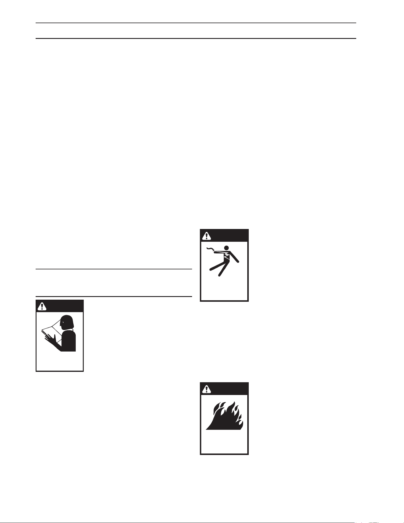
IMPORTANT SAFETY
INFORMATION
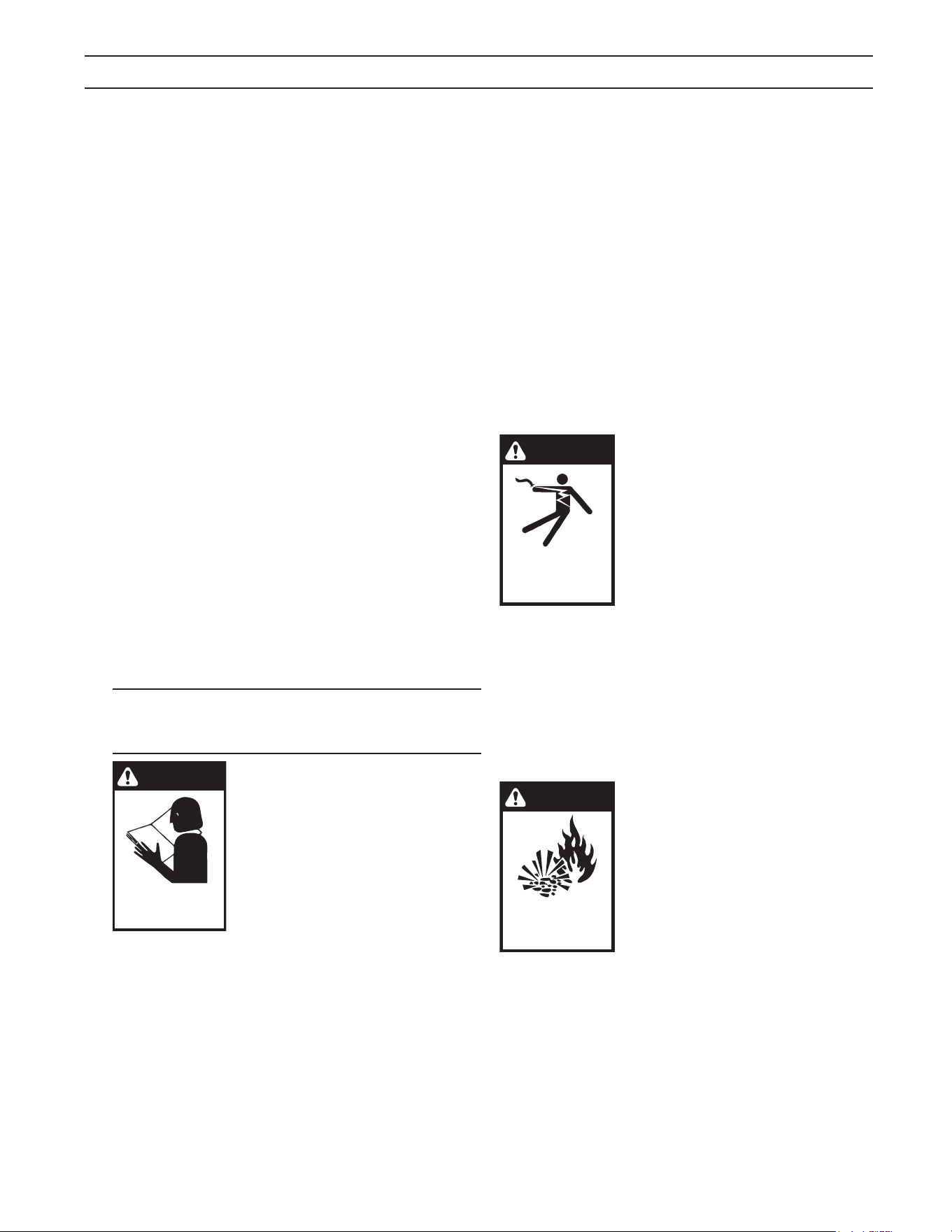
WARNING
READ OPERATOR’S
MANUAL THOROUGHLY
PRIOR TO USE.
OPERATIONS
SAFETY
MAINTENANCE
WARNING: To reduce the risk of
injury, read operating
instructions carefully before
using.
AVERTISSEMENT: Pour réduire
le risque de blessures, lire
attentivement les instructions
de fonctionnement avant
l'utilisation.
1. Read the owner's manual thoroughly. Failure to
follow instructions could cause malfunction of the
machine and result in death, serious bodily injury
and/or property damage.
2. Know how to stop the machine and bleed
pressure quickly. Be thoroughly familiar with the
controls.
3. Stay alert — watch what you are doing.
4. All installations must comply with local codes.
Contact your electrician, plumber, utility company
or the selling distributor for specic details. If
your machine is rated 250 volts or less, single
phase will be provided with a ground fault circuit
interrupter (GFCI). If rated more than 250 volts,
or more than single phase this product should
only be connected to a power supply receptacle
protected by a GFCI.
DANGER: Improper connection of the equipment-
grounding conductor can result in a risk of
electrocution. Check with a qualied electrician
or service personnel if you are in doubt as to
whether the outlet is properly grounded. Do
not modify the plug provided with the product
- if it will not t the outlet, have a proper outlet
installed by a qualied electrician. Do not use any
type of adaptor with this product
DANGER: Une mauvaise connexion du
conducteur de terre de l'équipement peut
entraîner un risque d'électrocution. Vérier
auprès d'un électricien qualié ou du personnel
d'entretien si vous avez des doutes quant à
savoir si la sortie est correctement mise à la
masse. Ne pas modier la che fournie avec le
produit - si elle n'entre pas dans la sortie, faire
installer une sortie appropriée par un électricien
qualié. Ne jamais utiliser un adaptateur avec ce
produit.
DANGER
KEEP WATER
SPRAY AWAY FROM
ELECTRICAL WIRING.
WARNING: Keep wand, hose,
and water spray away from
electric wiring or fatal electric
shock may result.
DANGER: Garder la lance, le
boyau et le jet d'eau à l'écart de
tout câblage électrique ou des
chocs électriques mortels pou
raient survenir.
5. To protect the operator from electrical shock,
the machine must be electrically grounded.
It is the responsibility of the owner to connect this
machine to a UL grounded receptacle of proper
voltage and amperage ratings. Do not spray
water on or near electrical components. Do not
touch machine with wet hands or while standing
in water. Always disconnect power before
servicing.
WARNING
RISK OF FIRE.
DO NOT SPRAY
FLAMMABLE LIQUIDS
WARNING: Flammable liquids
can create fumes which can
ignite, causing property damage
or severe injury.
AVERTISSEMENT: Des liquides
inammables peuvent produire
des vapeurs qui peuvent
s'enammer, causant ainsi des
dommages à la propriété ou des
blessures graves.
WARNING: Risk of explosion — Do not spray
ammable liquids.
Manual Dual Mister 9.808-246.0 - J
5
during operation.
11. Never make adjustments on machine while in
operation.
12. Be certain all quick coupler ttings are secured
before using pressure washer.
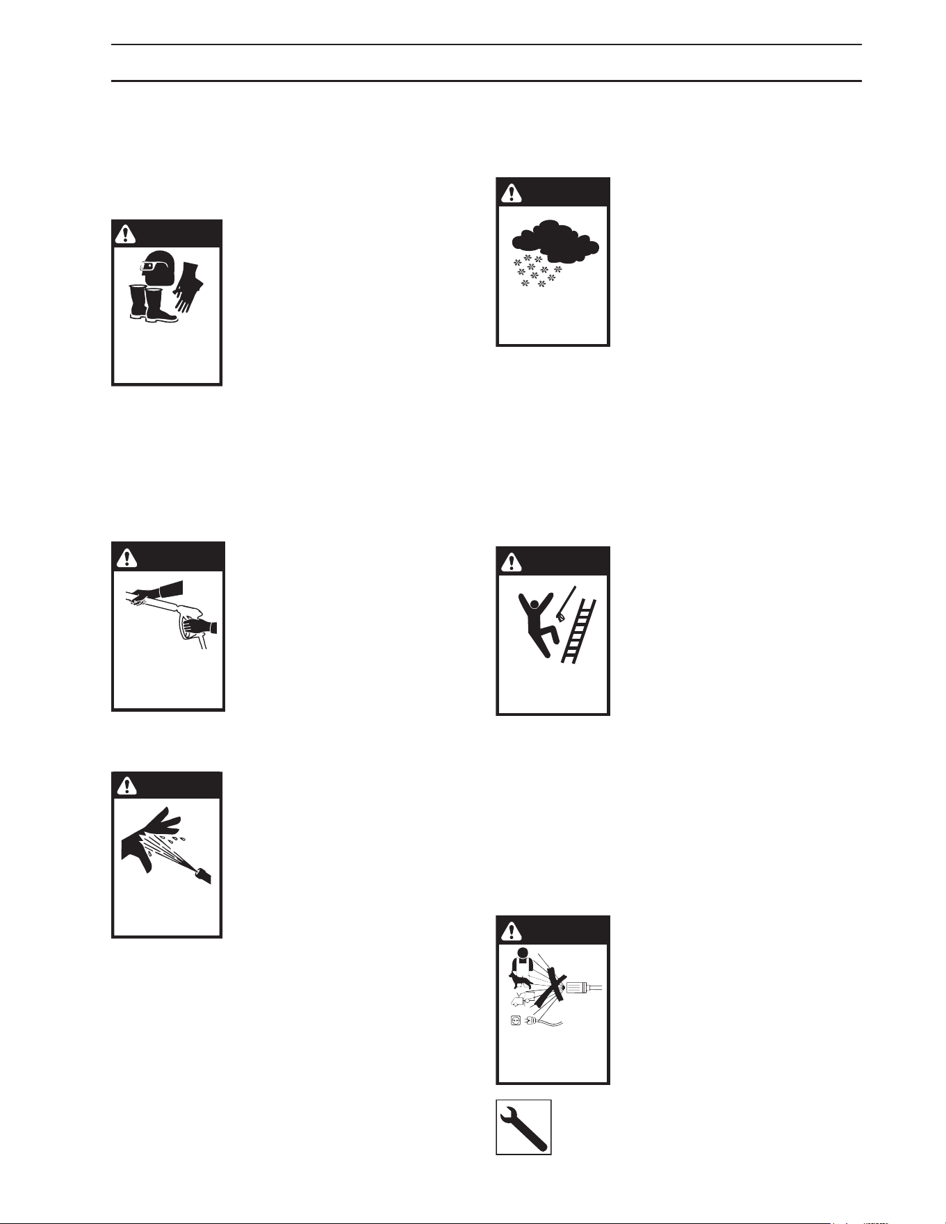
WARNING
PROCTECT FROM
FREEZING
WARNING: Protect machine from
freezing.
AVERTISSEMENT: Protéger la
machine contre le gel.
13. To keep machine in best
operating conditions, it is important
you protect machine from freezing.
Failure to protect machine from
freezing could cause malfunction
of the machine and result in death, serious bodily
injury, and/or property damage. Follow storage
instructions specied in this manual.
14. Inlet water must be clean fresh water and no
hotter then 90°F.
15. Manufacturer will not be liable for any changes
made to our standard machines or any
components not purchased from us.
16. The best insurance against an accident is
precaution and knowledge of the machine.
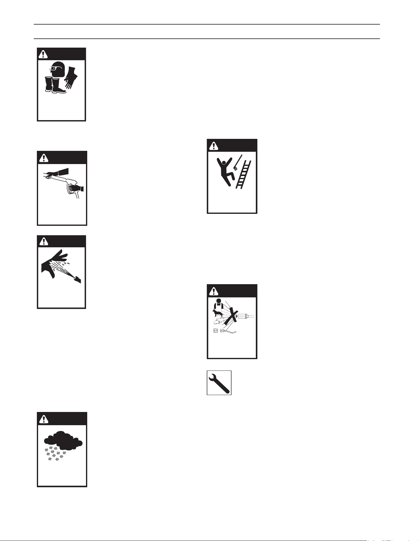
WARNING
RISK OF INJURY
FROM FALLS WHEN
USING LADDER.
WARNING: Be extremely careful
when using a ladder, scaolding
or any other relatively unstable
location. The cleaning area
should have adequate slopes
and drainage to reduce the
possibility of a fall due to
slippery surfaces.
AVERTISSEMENT: Une modication non
autorisée de la machine ou l'utilisation de pièces
de rechange non approuvées peut causer des
lésions corporelles et/ou des dommages à la
propriété, et annulera la garantie du fabricant.
17. Do not overreach or stand on unstable support.
Keep good footing and balance at all times.
18. Do not operate this machine when fatigued
or under the inuence of alcohol, prescription
medications, or drugs.
WARNING
DO NOT SPRAY
MACHINE OR ANY
PEOPLE, ANIMALS OR
ELECTRICAL PARTS.
WARNING: Do not spray machine
or any people, animals or
electrical parts.
AVERTISSEMENT: Ne pas
vaporiser sur la machine ou les
gens, les animaux ou les pièces
électriques.
Follow the maintenance instructions
specied in the manual.
IMPORTANT SAFETY INFORMATION
AVERTISSEMENT: Risque d'incendie - Ne pas
pulvériser de liquides inammables.
6. Do not allow acids, caustic or abrasive uids to
pass through the pump.
7. Never run pump dry or leave spray gun closed
longer than 1-2 minutes.
8. Keep operating area clear of all persons.
WARNING
USE PROTECTIVE
EYE WEAR
AND CLOTHING
WHEN OPERATING
THIS EQUIPMENT.
WARNING: High pressure spray
can cause paint chips or other
particles to become airborne and
y at high speeds. To avoid
personal injury, eye, hand and
foot safety devices must be worn.
AVERTISSEMENT: Un jet
hautepression peut écailler la
peinture ou provoquer l'émission
d'autres particules dans l'air et leur projection
à hautes vitesses. Pour éviter les lésions
corporelles, une protection des yeux, du visage,
des mains et des pieds doit être portée lors de
l'utilisation de cet équipement.
9. Eye, hand, and foot protection must be worn
when using this equipment.
WARNING
TRIGGER GUN KICKS
BACK — HOLD WITH
BOTH HANDS
WARNING: Grip cleaning wand
securely with both hands before
starting. Failure to do this could
result in injury from a whipping
wand.
AVERTISSEMENT: Agripper la
lance de nettoyage avec les deux
mains avant de commencer. Le
non-respect de cette consigne
pourrait mener à des blessures causées par le
mouvement violent de la lance.
WARNING
RISK OF INJECTION
OR SEVERE INJURY
TO PERSONS. KEEP
CLEAR OF NOZZLE.
WARNING: High pressure
developed by these machines will
cause personal injury or
equipment damage. Keep clear of
nozzle. Use caution when
operating. Do not direct
discharge stream at people, or
severe injury or death will result.
AVERTISSEMENT: La haute pression générée par
ces machines causera des lésions corporelles
ou des dommages à l'équipement. Se tenir à
l'écart de la buse. Faire preuve de prudence lors
de l'utilisation. Ne pas décharger directement le
jet vers des personnes ou des animaux, car cela
risquerait de causer des blessures graves ou
même la mort.
10. To reduce the risk of injury, close supervision is
necessary when a machine is used near children.
Do not allow children to operate the pressure
washer. This machine must be attended
Manual Dual Mister 9.808-246.0 - J
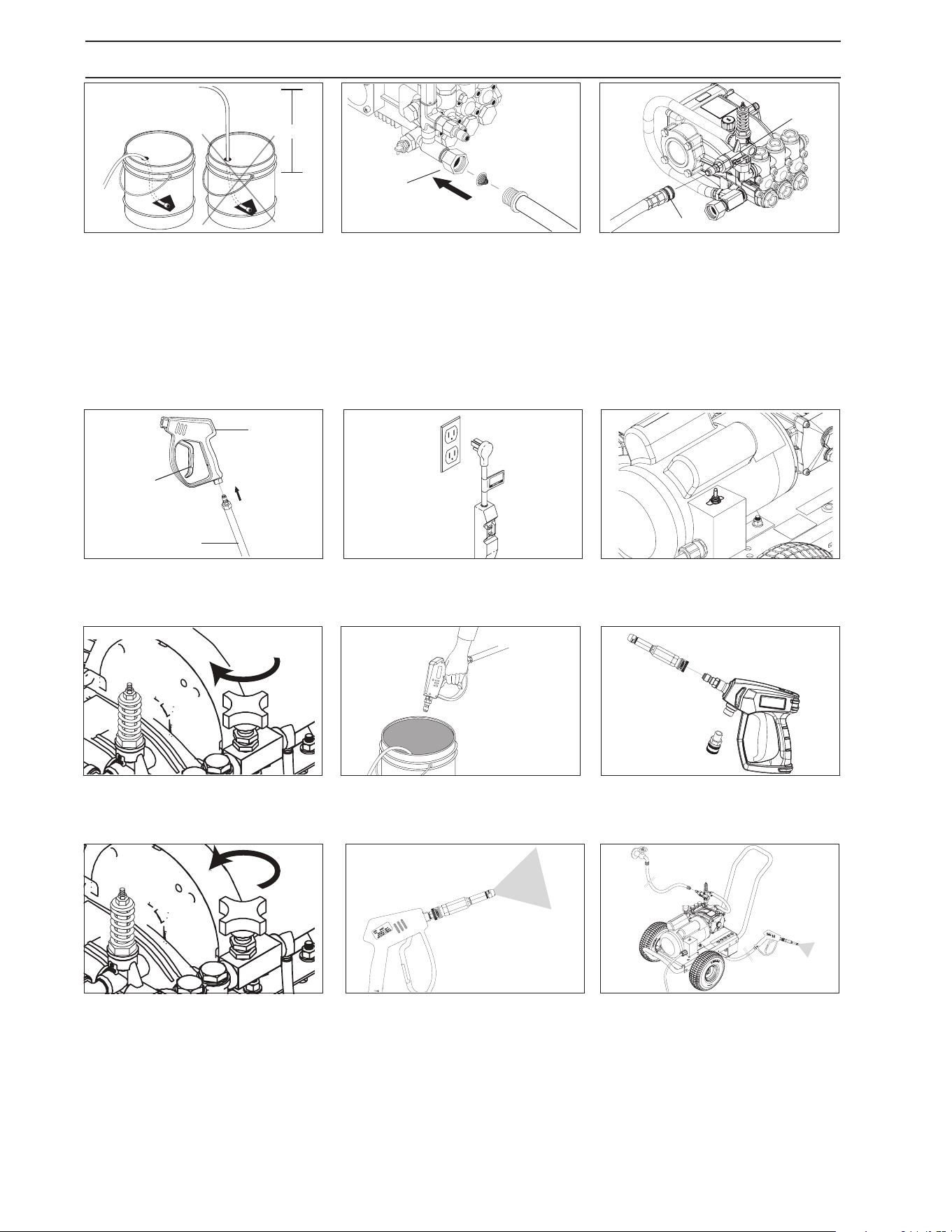
6
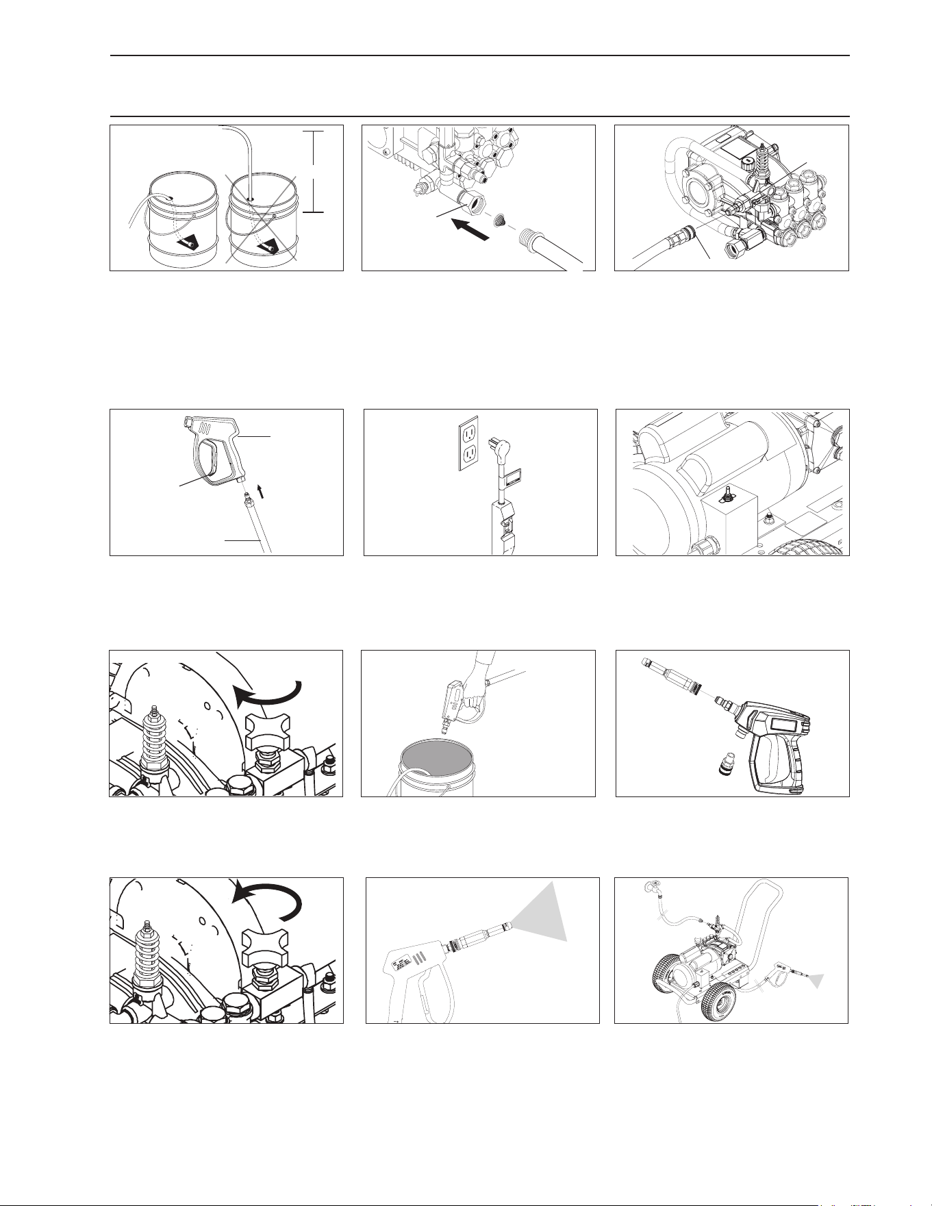
STEP 1: Attach ½” hose to a disin-
fectant bucket (Recomendable that
water inlet is at oor level).
We recommend Vital Oxide.
STEP 6: Start up the machine.STEP 5: Connect to apropriate
power supply. Push reset button
on GFCI.
STEP 9: Attach misting nozzle into
the spray gun.
STEP 3: Connect ¼” high pressure
hose to the discharge nipple. Push
coupler collar forward until secure.
STEP 7: Close metering valve to
purge hose.
STEP 10: Open metering valve to
use Misting mode.
CAUTION: If valve stays close
in misting mode nozzle may get
damage.
ATTENTION: Si la soupape reste
fermée en mode brumisation, la
buse peut être endommagée.
STEP 2: Connect ½” hose to pump
Water inlet. Inspect inlets.
CAUTION: Do not run the pump
without water or pump damage
will result.
ATTENTION: Ne pas faire fonc-
tionner la pompe sans eau pour
éviter d'endommager la pompe.
STEP 8: Purge any air trapped in
hose (Recommend to do this over
the disinfectant bucket).
STEP 11: Ready to use, mist Vital
Oxide disinfectant.
IMPORTANT: After nish the job,
ush all chemical remains from
the unit. Fill tank with fresh water
and ush all system.
IMPORTANT: Une fois le travail
terminé, rincer tous les restes
chimiques de l'unité. Remplir le
réservoir d'eau douce et rincer
tout le système.
>19”
OPERATING INSTRUCTIONS FOR MISTING MODE
Pump
Water Inlet
Garden Hose
Discharge
Nipple
High
Pressure
Hose
Coupler Collar
STEP 4: Attach the high pressure
hose to the spray gun.
Safety
Latch
Spray
Gun
High
Pressure Hose
Manual Dual Mister 9.808-246.0 - J
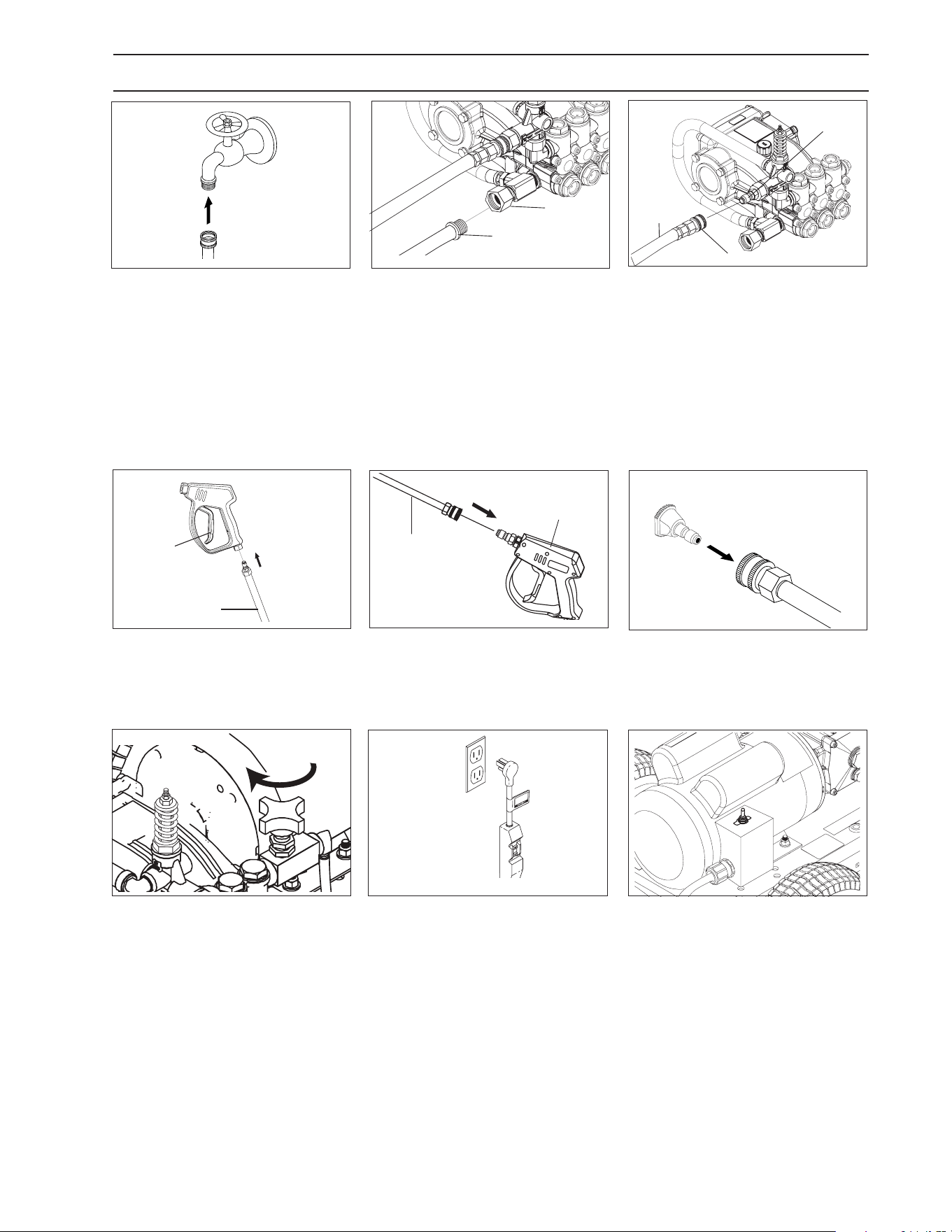
7
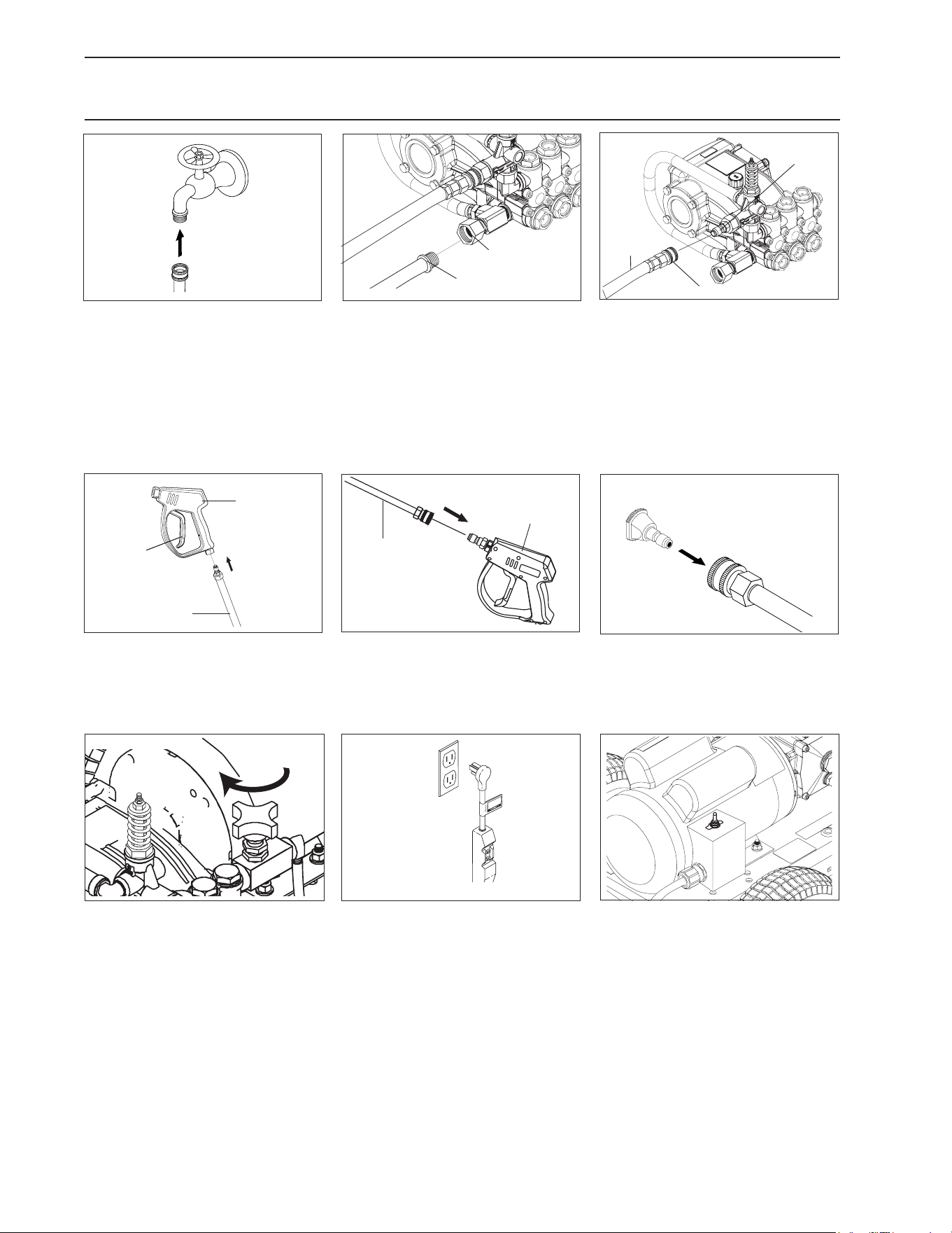
OPERATING INSTRUCTIONS FOR HIGH PRESSURE MODE
STEP 4: Attach the high pressure
hose to the spray gun.
STEP 7: Close metering valve to
purge hose.
CAUTION: If valve is open, pres-
sure wont reach rate.
ATTENTION: Si la soupape est
ouverte, la pression n'atteindra
pas le taux.
STEP 5: Attach wand to spray gun.
STEP 6: Pull spring-loaded collar
of the wand coupler back to insert
your choice of pressure nozzle.
STEP 1: Connect ½” hose to cold
water inlet.
STEP 2: Check inlets lters, remove
debris, then connect the garden
hose to pump water inlet.
CAUTION: Do not run the pump
without water or pump damage
will result.
ATTENTION: Ne pas faire fonc-
tionner la pompe sans eau pour
éviter d'endommager la pompe.
STEP 3: Connect ¼” high pressure
hose to the discharge nipple. Push
coupler collar forward until secure.
Safety
Latch
Spray
Gun
High
Pressure Hose
Wand
Wand
Coupler
Pressure
Nozzle
Discharge
Nipple
High
Pressure
Hose
Cold
Water
Source
Garden
Hose
Pump
Water Inlet
Garden
Hose
Coupler Collar
STEP 9: Start up the machine.
Spray
Gun/Wand
STEP 8: Connect to apropriate
power supply. Push reset button
on GFCI.
Manual Dual Mister 9.808-246.0 - J
8
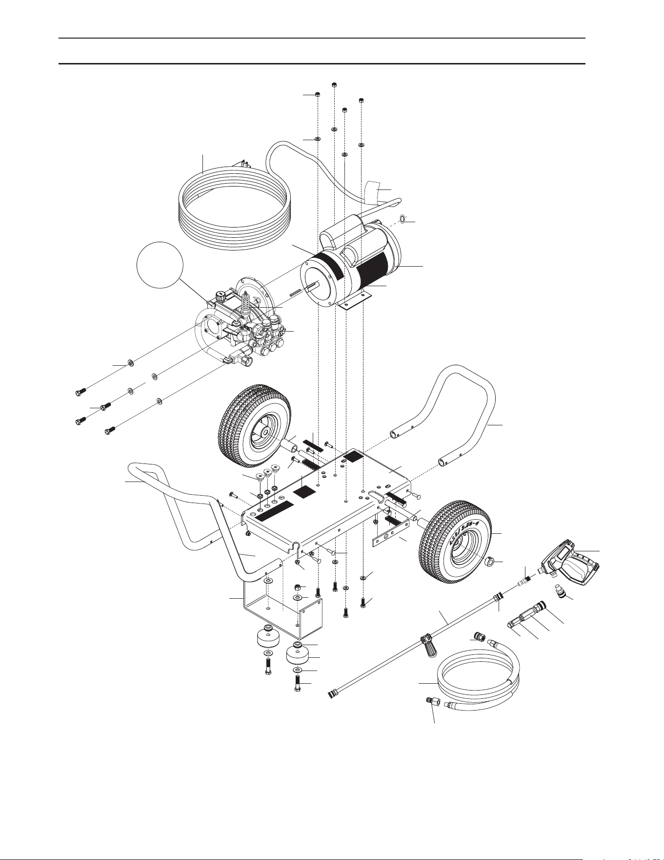
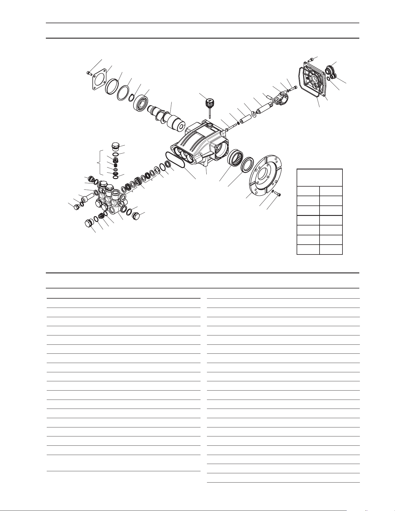
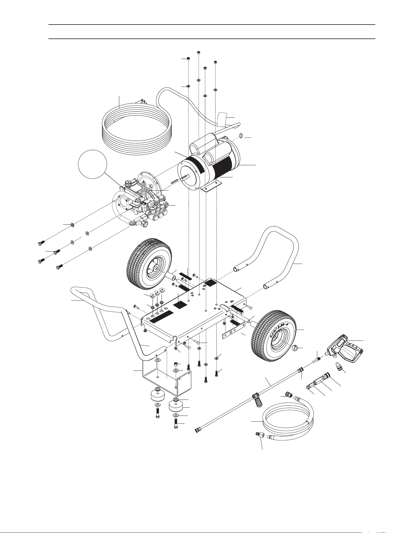
EXPLODED VIEW
9
12
11
13
26
37
25
40
41
42
43
44
45
28
29
33
27
2
3
18
7
6
34
35
5
47
37
10
8
9
15
14
23
22
4
16
46
1
For
Detail
See Pump
Assy
20
21
19
24
23
38
39
17
48
31
32

Manual Dual Mister 9.808-246.0 - J
9
EXPLODED VIEW PARTS LIST
ITEM PART NO. DESCRIPTION QTY
1 8.924-115.0 Al Base Direct Drive 1
2 8.924-394.0 Al Handle 1
3 8.924-393.0 Al Bumper 1
4 9.803-097.0 Axle, 5/8 X 20.125 Long 1
5 8.924-179.0 AL Spacer Tube DD Frame 2
6 8.756-365.0 Wheel 10" at free 1
7 9.802-782.0 Collar, 5/8" Bore Shaft 3010 2
8 9.197-003.0 3/8-16 NE Nylon Insert L/N ZC 5UM White 2
9 9.802-817.0 Washer, 3/8" x 1" 4
10 8.924-116.0 Foot AL DD Frame CW 1
11 9.802-064.0 Grommet, Rubber, Nozzle Holder 2
12 9.802-066.0 Pad Soft Rubber 2
13 9.196-041.0 Hex Head Bolt 3/8-16 X 1-3/4 2
14 8.924-074.0 Camaro Silver Axle Holder DD CW 1
15 9.802-706.0 Bolt, 1/4"-20 x 1-3/4" Carriage Zinc 8
16 9.197-010.0 1/4-20'' Nylon Insert Lock Nut With Flange 10
17 8.759-044.0 Motor 1.5HP 1PH 115/230V F3 1750RPM 56C 1
18 8.750-299.0 Unloader, VRT3, 8 GPM @4500 PSI 1
19 8.754-761.0 Pump, Leuco LF2030S, 2.1@3000, 1725RPM 1
20 9.198-004.0 3/8", USS F/W Zinc 4
21 9.802-720.0 Bolt, 3/8" x 1", NC HH 4
22 9.802-710.0 Screw 5/16" x 1" NC 4
23 8.718-980.0 Washer, 5/16" Flat, SAE 8
24 9.802-776.0 Nut, 5/16-18, ESNA 4
25 4.760-846.0 Pistol G3/8 155°C package Generic 1
26 8.783-039.0 Wand 30" Zinc Plated, Handle & Coupler 1
27 9.802-166.0 Coupler, 3/8" Socket, Female, Brass 2
28 8.925-393.0 Hose 1/4"x75' 4000 PSI SWxSW CPL S120 1
29 9.802-170.0 Coupler, 3/8" Plug, Female, Steel Zinc 1
30 8.900-305.0 Label, Landa, Home Depot, ZE Warning 1
31 9.800-037.0 Label, French Inst./Warn 1
32 9.803-834.0 Washer, Reducing 3/4" x 1/2" 1
33 9.802-169.0 Coupler, 3/8"Socket, Male, Brass 1
34 8.755-187.0 Grommet, Rubber, Nozzle Holder Base 3/16 5
35 8.712-338.0 Nozzle, SAQCMEG 1503.5, Yellow 1
8.712-339.0 Nozzle, SAQCMEG, 2503.5, Green 1
8.712-340.0 Nozzle, SAQCMEG 4003.5, White 1
36 9.800-016.0 Label, Disconnect Power Supply 1
37 8.755-210.0 Four Nozzle Label, Black 1
38 9.802-432.0 GFCI, 120V 15A, W/ 36' 12-3 CORD 1
39 8.932-969.0 Label, Warning, Service Cord 1
40 8.707-139.0 Coupler, 1/4"Plug, Male, Steel/Zinc 1
41 9.802-164.0 Coupler, 1/4"Socket, Female, Brass 1
42 8.756-030.0 Coupler, 1/4 Socket, Male, Brass 1
43 8.709-175.0 Filter,High Pressure 1/4'Npt-Fx1/4'Np 1
44 8.758-918.0 Adapter 9/16 X 1/4 1
45 8.756-697.0 Fuel Nozzle, 2.50 X 80 BZ 1
46 9.800-049.0 Label, Manufacturer's cleaning solution 1
47 8.757-432.0 Bolt, 1/4-20 X 3/4,Carriage ST CL5 ZNPLT 2
Manual Dual Mister 9.808-246.0 - J
10
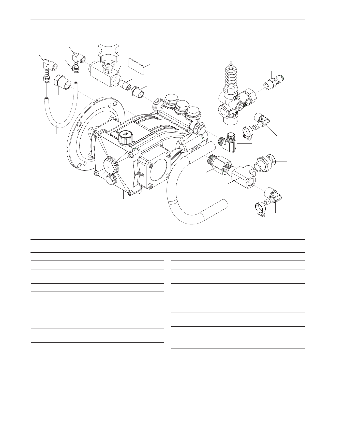
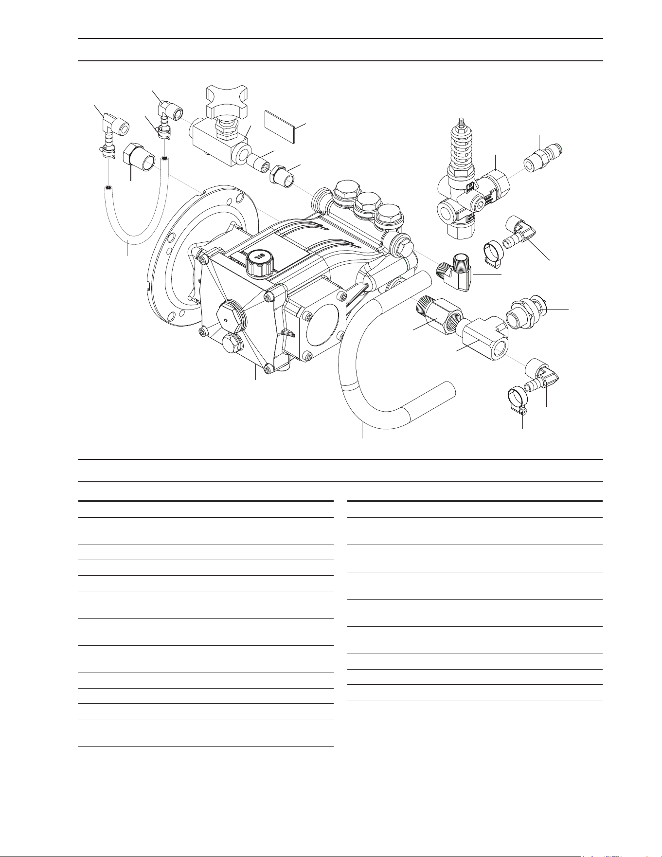
PUMP ASSEMBLY EXPLODED VIEW
PUMP ASSY EXPLODED VIEW PARTS LIST
3
1
7
11
4
6
16
21
15
19
18
5
9
8
10
2
17
14
20
13
ITEM PART NO. DESCRIPTION QTY
1 8.750-299.0 Unloader, Vrt3, 8 Gpm @4500 Psi 1
2 8.757-193.0 Adapter, 1/2" F-Nptf X 1/2"
M-Nptf, Brass 1
3 8.707-152.0 Nipple, 3/8", Male, Ssteel 1
4 8.759-036.0 Elbow Stainless Steel 3/8"
NPTF 1
5 8.711-785.0 Hose, 3/8 Push On 1
6 8.758-069.0 Pump LEUCO LFP2030S,
2.1@3000, 1725RPM 1
7 8.705-119.0 Hose Barb, Elbow,
3/8"Barbx3/8"Mpt/90Deg 1
8 8.758-199.0 Hose Barb Elbow 3/8"X1/2"
90 Deg W/Slnt 1
9 8.623-315.0 Clamp, 3/8 Hose (D-Slot) 2
10 8.757-257.0 Tee, Street 1/2" 1
11 8.757-203.0 Swivel, 1/2" M-Nptf X 3/4" Ghf 1
12 9.804-016.0 Filter Screen Washer,
Garden Hose/30Mesh 1
ITEM PART NO. DESCRIPTION QTY
13 8.707-317.0 Valve, Flow Control 1
14 8.706-297.0 Bushing, 3/8" X 1/4"
Steel Yellow Chrom 1
15 8.706-965.0 Hose Barb, 1/4" Barb X 3/8"
Npt-M, 90 1
16 8.706-294.0 Bushing, 1/2" X 3/8",
Steel P/N-5406- 1
17 8.757-337.0 Nipple, 1/4" Close Sch 80
Steel, W/Slnt 1
18 8.757-205.0 Hose Barb, 1/4" Barb
X 1/4" M-Nptf, 90 1
19 6.390-126.0 Clamp Hose 2
20 8.758-919.0 Label Valve Label. 1
21 9.802-254.0 Hose, 1/4 Push-On 5"
Manual Dual Mister 9.808-246.0 - J
11
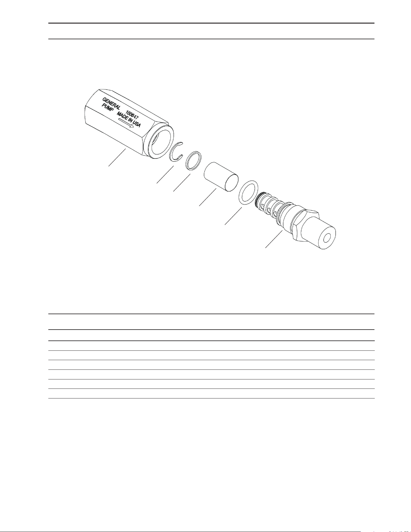
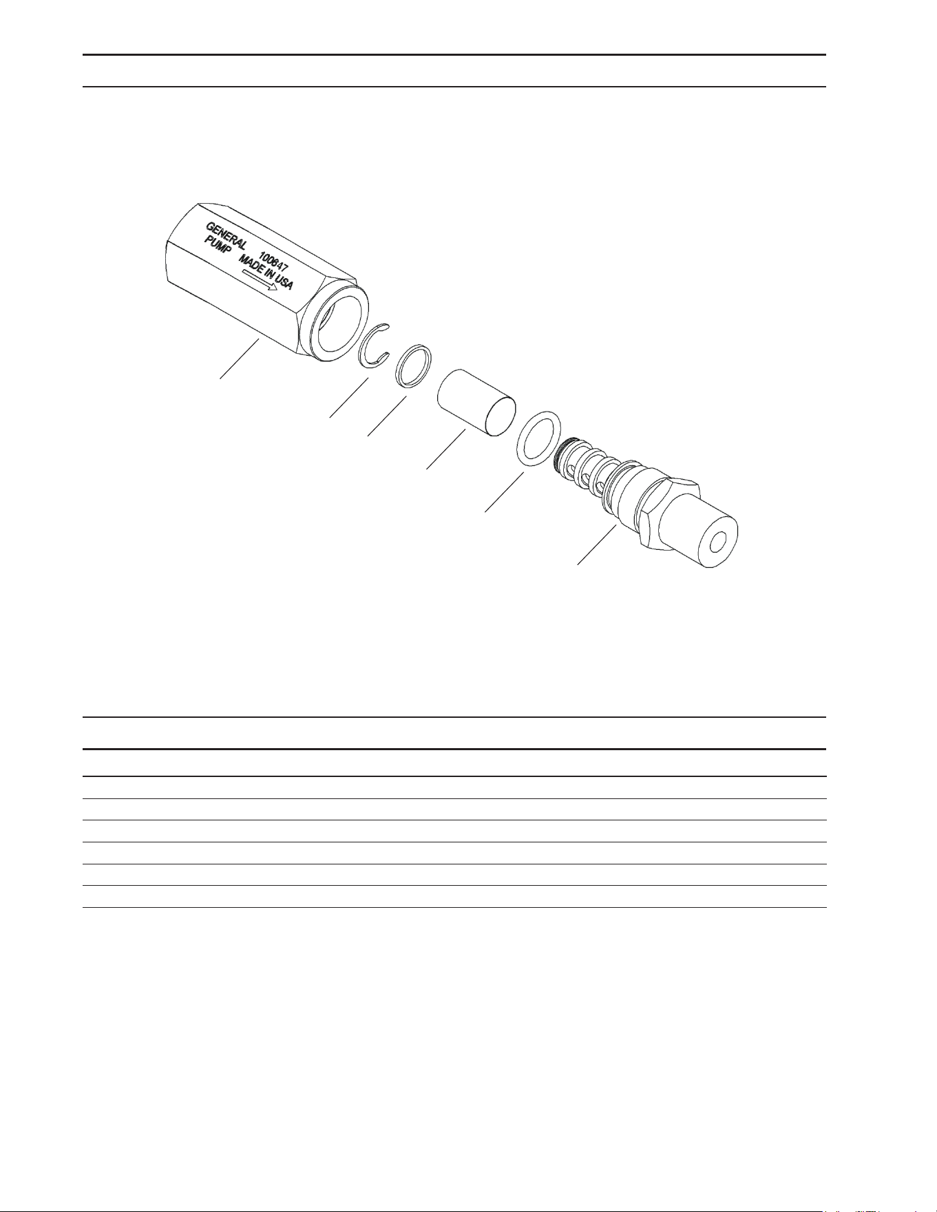
FILTER EXPLODED VIEW
FILTER PARTS LIST
ITEM DESCRIPTION QTY
1 Housing, Nozzle Filter, 1/4 NPT-F 1
2 Retainer, Filter 1
3 Screen, 100 Mesh, T304SS 1
4 O-Ring, 70 Duro, Buna-N, .426 ID x .070 CS 1
5 Outlet Fitting, Nozzle Filter, 1/4 NTP-M 1
6 Retainer, External, SS 1
1
6
2
3
4
5
Manual Dual Mister 9.808-246.0 - J
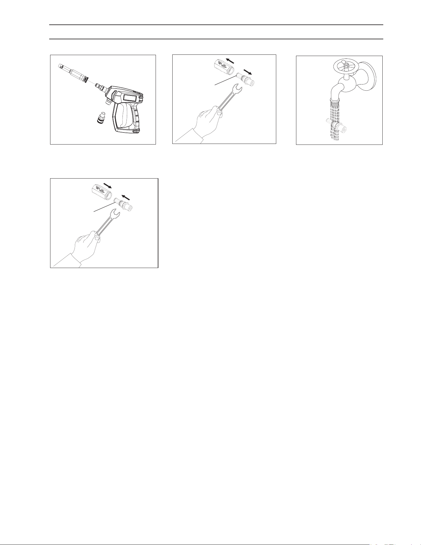
12
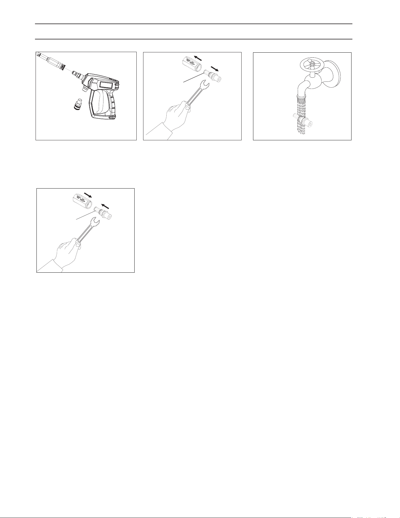
CLEANING THE WATER INLET FILTER
STEP 1: Disconnect Spray nozzle
From the machine.
Filter
STEP 2: Pull out water inlet lter.
Use the necessary tools.
STEP 3: Rinse out water inlet lter
in warm water.
STEP 4: Assemble the water inlet
lter. Use the necessary tools.
Filter
Manual Dual Mister 9.808-246.0 - J
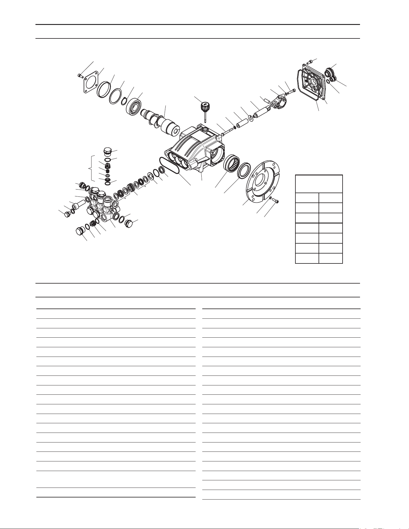
13
LF 2030S SERIES PUMP EXPLODED VIEW
HF 2030S SERIES PUMP PARTS LIST
13
6
8
1
3
9
10
11
12
13
14
15
21
20
17
16
12
14
15
22
23
24
25
26
27
28
31
32
33
35
39
40
41
42
43
45
44
37
46
47
48
26
2
5
7
18
19
29
30
34
36
38
49
4
37
50
21
ITEM PART NO. DESCRIPTION QTY
19 8.754-850.0 Washer, Lock 2
20 9.803-198.0 Washer, Copper G3/8 1
21 8.707-262.0 Plug, Brass G3/8 2
22* See Kits Below Valve Seat 6
23* See Kits Below Valve Plate 6
24* See Kits Below Valve Spring 6
25* See Kits Below Valve Cage 6
26 9.802-939.0 Screw, M6 X 16 8
27 8.717-137.0 Bearing Cover 1
28 9.803-954.0 Bearing Seal 1
29 8.754-843.0 Seal Spacer, Crankshaft 1
30 9.802-914.0 Snap Ring, 25 mm 1
31 9.803-955.0 Bearing, Ball 1
32 8.754-836.0 Shaft, 5/8" Hollow 1
33 8.754-219.0 Oil Dipstick 1
34 8.754-840.0 Bearing Needle 1
35 8.754-826.0 Seal, Crankshaft 1
36 8.754-844.0 Flange, Motor 1
37 9.803-210.0 Washer 10
38 8.752-824.0 Screw, 6 mm 4
ITEM PART NO. DESCRIPTION QTY
1 8.754-841.0 Crankcase 1
2 8.754-846.0 O-ring Ø1.78 X 72.75 1
3* See Kits Below Plunger Oil Seal 3
4* See Kits Below O-ring Ø1.78 X 26.7 3
5* See Kits Below Washer, Pressure Ring 3
6* See Kits Below U-Seal 3
7* See Kits Below Pressure Ring 3
8* See Kits Below U-Seal 3
9 9.803-199.0 Washer, Copper G1/2 1
10 9.802-926.0 Plug, Brass G1/2 1
11 8.754-852.0 Manifold (16mm Models) 1
8.754-853.0 Manifold (14mm Models) 1
12* 8.717-233.0 O-ring Ø1.78 X 15.6 6
13* See Kits Below Valve Assembly 6
14* 9.803-948.0 O-ring Ø1.78 X 18.77 6
15 9.803-949.0 Valve Plug 6
16 8.754-851.0 Plug, Brass G1/4 (16mm) 1
17 8.754-845.0 Washer, Copper G1/4
(16mm Models) 1
18 8.754-854.0 Bolt, Manifold M14 X 40 2
TORQUE
SPECS
Item # Ft.-lbs
15 65
18 55
26 8
38 10
39 10
46 10
8.924-736.0 LF 2030S
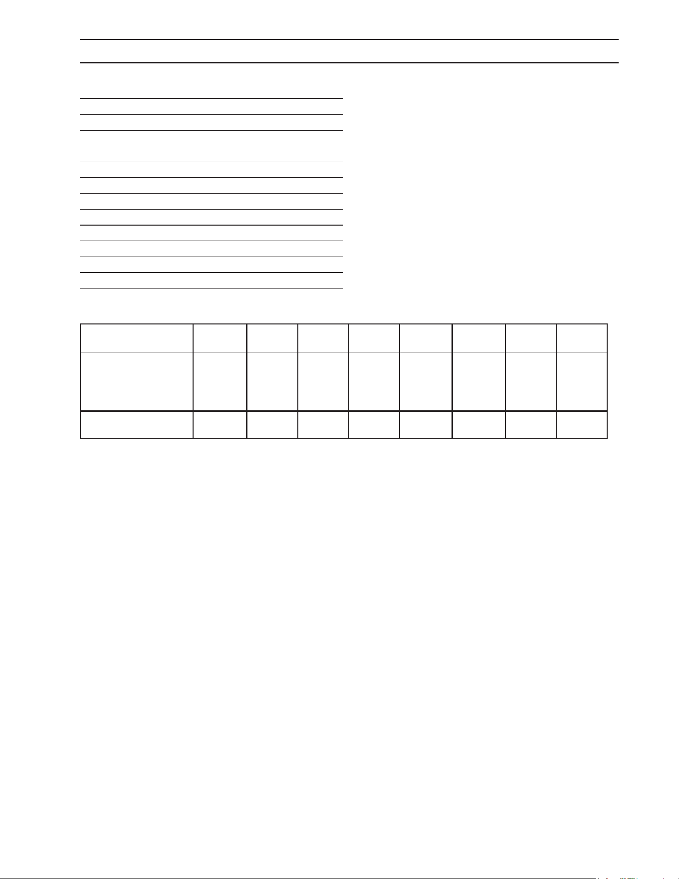
Manual Dual Mister 9.808-246.0 - J
14
ITEM PART NO. DESCRIPTION QTY
39* 8.754-855.0 Bolt, Plunger 3
40* 8.754-092.0 Spacer, Copper 3
41 8.754-848.0 Plunger, 16mm 3
42 9.803-962.0 Spacer, Copper 3
43 8.754-827.0 Plunger Rod 3
44 9.803-965.0 Connecting Rod Pin 3
45 9.803-966.0 Connecting Rod 3
46 8.933-020.0 Screw, Connecting Rod 6
47 8.754-847.0 O-ring Ø2.62 X 111.62 1
48 8.754-842.0 Cover, Crankcase 1
49 9.803-906.0 O-ring Ø1.78 X 14 1
50 9.803-202.0 Sight Glass, G3/4 1
REPAIR KIT NUMBER 8.754-860.0 8.754-856.0 8.754-861.0 8.754-857.0 8.754-862.0 8.754-858.0 8.754-859.0 9.803-937.0
KIT DESCRIPTION
Plunger
Seals
14 mm**
Plunger
Seals 16
mm**
Seal Pack-
ing
14 mm**
Seal Pack-
ing
16
mm**
Plunger
14 mm**
Plunger
16 mm**
Complete
Valve
Plunger Oil
Seals
ITEM NUMBERS
INCLUDED
4, 6, 8 4, 6, 8 4, 5, 6, 7, 8 4, 5, 6, 7, 8
39, 40, 41,
42
39, 40, 41,
42
12, 13, 14 3
LF 2030S SERIES PUMP PARTS LIST
Manual Dual Mister 9.808-246.0 - J
15
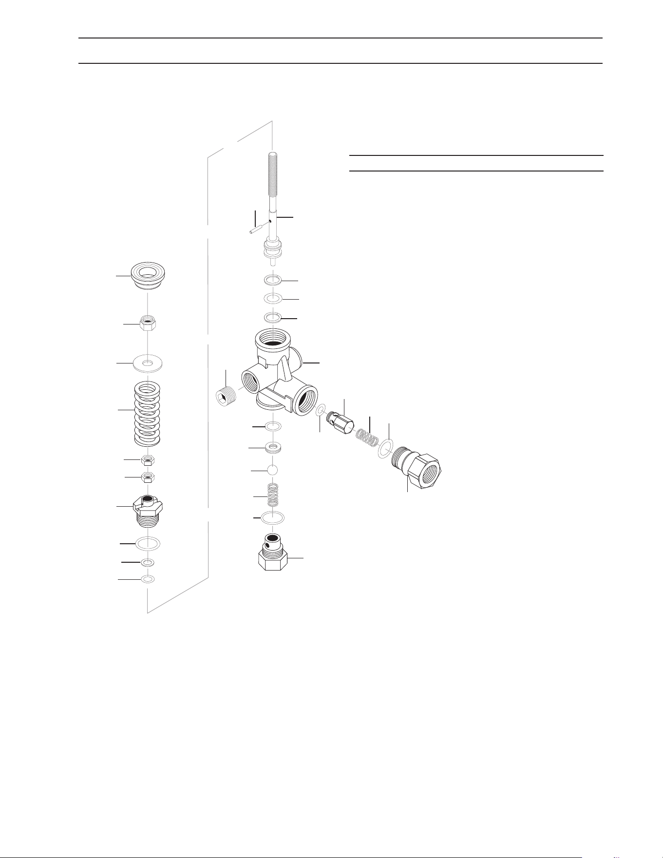
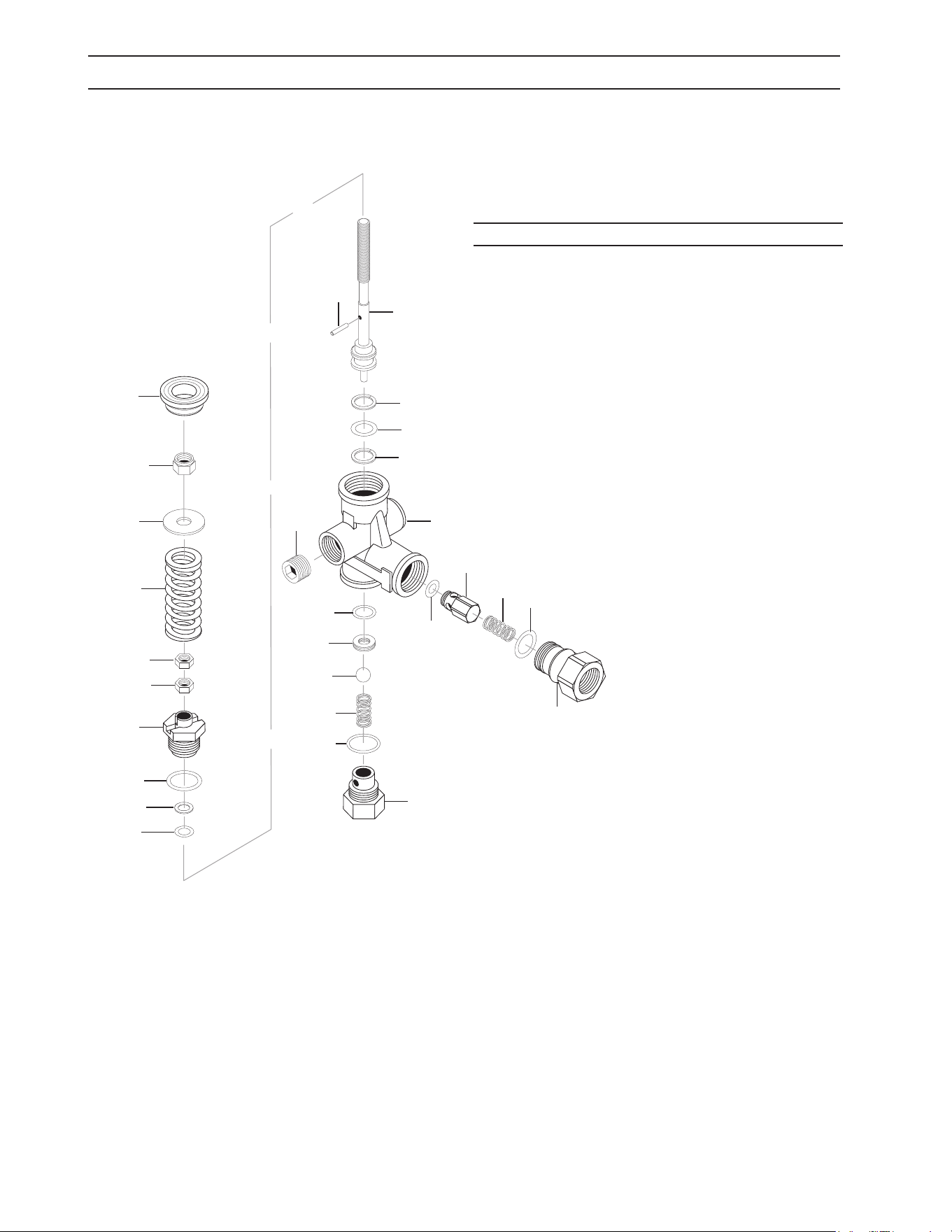
VRT3 UNLOADER EXPLODED VIEW AND PART S LIST
9
8
23
26
3
16
1
10
24
11
6
4
13
14
20
25
12
22
19
15
2
15
21
17
7
9
5
6
8.750-299.0, 8 GPM, 4500 PSI
ITEM PART NO. DESCRIPTION QTY
25 8.750-712.0 Outlet Fitting 1
8.750-709.0 Repair Kit, VRT3, 2320/3630
PSI
8.750-710.0 Repair Kit, VRT3, 4500 PSI
(Kit Items: 1, 4, 8-12, 16, 21-22)
Unloader Adjustment Procedures
1. Remove lock nut (Item 19).
2. Loosen the two (2) nuts (Item 15), move them upward on stem (Item 8) until you see 4 or more threads below the nut.
3. Start machine. Open the trigger of the spray gun. Increase pressure by turning adjustment knob (Item 18) clockwise until
pressure is at the desired operating pressure.
4. Tighten the lower nut (Item 15) tightly against the upper nut (Item 15).
Screw down lock nut (Item 19) onto the stem (Item 8) until the threads cut into the nylon insert of the lock nut (Item 19).
**Release the trigger of the spray gun and watch the pressure gauge for the pressure increase (“spike”). This “spike” SHOULD NOT
exceed 500 psi above the operating pressure. If “spike” pressure exceeds the 500 psi limit, re-adjust (lower) the nuts (Items 15) on the
stem (Item 8). Then repeat step #4.
Manual Dual Mister 9.808-246.0 - J
16
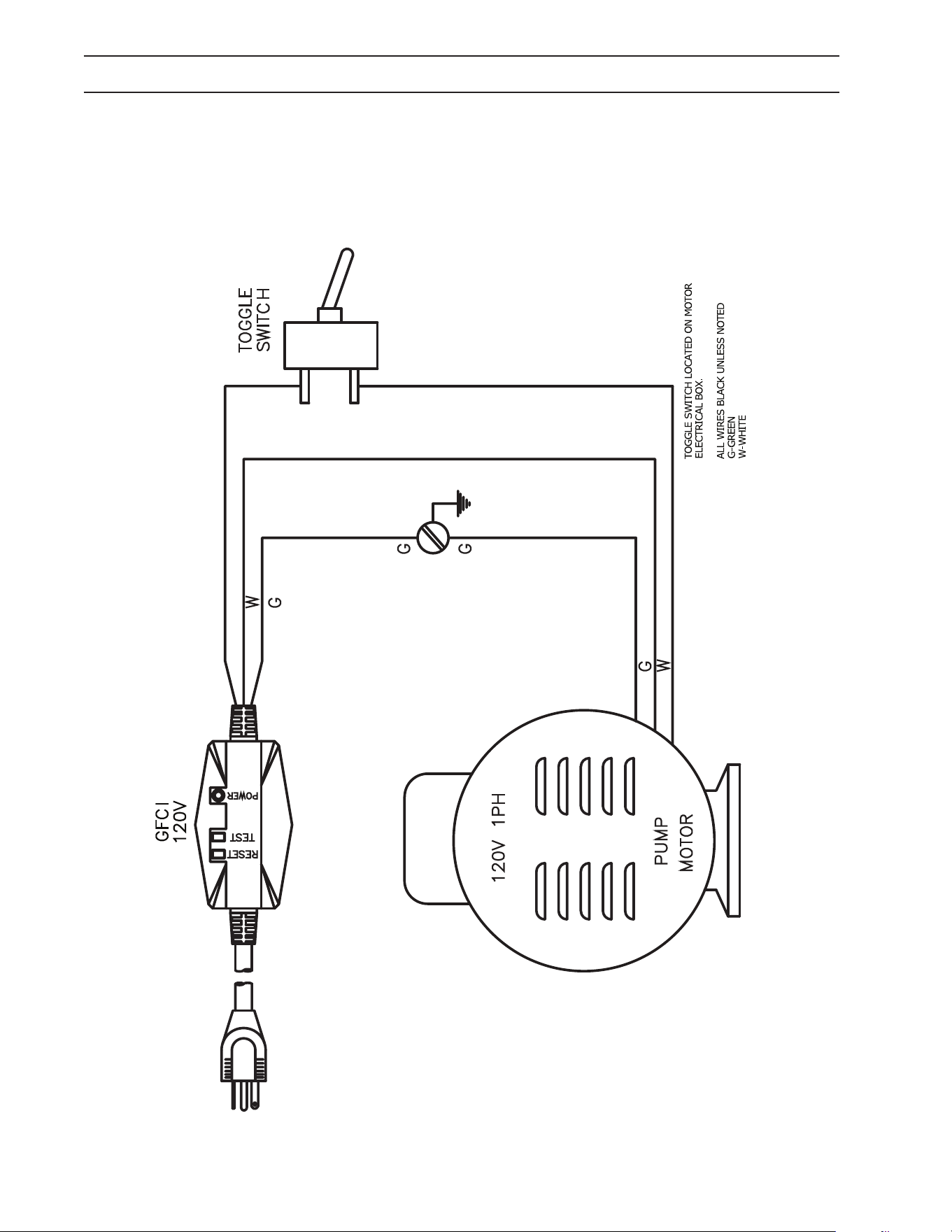
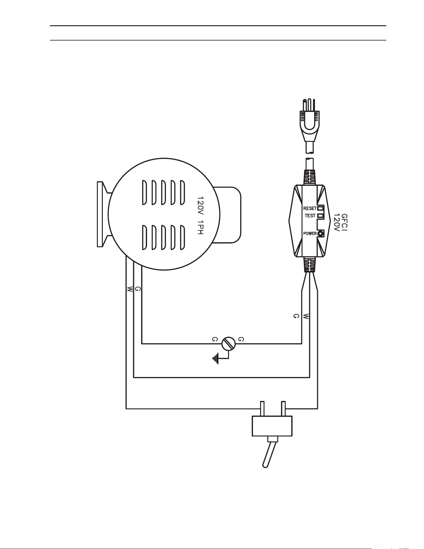
WIRING DIAGRAM
1.106-160.0 HD 2.0/1000 Dual Mister
Manual Dual Mister 9.808-246.0 - J
17
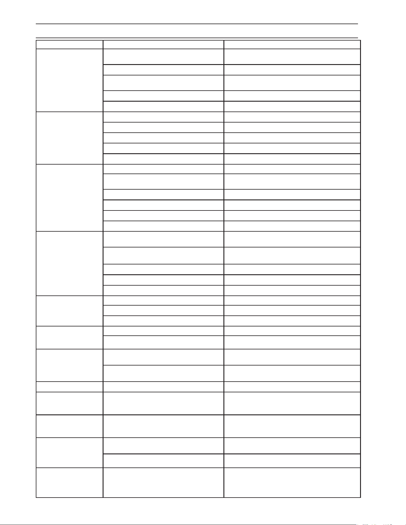
TROUBLESHOOTING
PROBLEM POSSIBLE CAUSE SOLUTION
PUMP RUNNING
NORMALLY BUT
PRESSURE LOW ON
INSTALLATION
Pump sucking air Check water supply and possibility of air seepage.
Check valves sticking Check and clean or replace if necessary.
Unloader valve seat faulty Check and replace if necessary.
Nozzle incorrectly sized Check and replace if necessary.
Worn piston packing Check and replace if necessary.
FLUCTUATING
PRESSURE
Valves worn Check and replace if necessary.
Blockage in valve Check and replace if necessary.
Pump sucking air Check water supply connections.
Worn piston packing Check and replace if necessary.
Insufcient water Check lter and hose for breakage.
PRESSURE LOW AFTER
PERIOD OF NORMAL
USE
Nozzle worn Check and replace if necessary.
Suction or delivery valves worn Check and replace if necessary.
Suction or delivery lines blocked Check and clean if necessary.
Unloader valve seat worn Check and replace if necessary.
Worn piston packing Check and replace if necessary.
Water temperature excessive Reduce to below 160
o
F.
PUMP NOISY
Air in suction line
Check water supply and connections on suction
line.
Broken or weak suction or delivery
valve spring
Check and replace if necessary.
Foreign matter in valves Check and clean if necessary.
Worn bearings Check and replace if necessary.
Excessive temperature of water Reduce to below 160
o
F.
PRESENCE OF WATER
IN PUMP OIL
Oil seal worn Check and replace if necessary.
High humidity in air Check and replace if necessary.
Piston packing worn Check and replace if necessary.
WATER DRIPPING FROM
UNDER PUMP
Piston packing worn Check and replace if necessary.
O-ring plunger retainer worn Check and replace if necessary.
WATER DRIPPING FROM
PUMP PROTECTOR
Water supply pressure too high (over
90 PSI)
Lower water supply pressure using a regulator.
Spray gun is in the off position for over
5 minutes
Turn machine off if not in use for over 1-2 minutes.
OIL DRIPPING
Oil seal worn Check and replace if necessary.
EXCESSIVE VIBRATION
IN HIGH PRESSURE
HOSE
Irregular functioning of the pump
valves
Check and replace if necessary.
MOTOR DOES
NOT START WHEN
SWITCHED ON
Plug not well connected or lack of
power supply
Check plug, cable and switch.
WHEN SWITCHING ON
THE MACHINE, MOTOR
HUMS BUT DOES NOT
RUN
Main voltage is insufcient, lower than
the minimum required
Check to make sure main power supply is ad-
equate.
The pump is stuck or frozen Check by turning the motor manually.
MOTOR STOPS
Tripped thermal overload due to over-
heating
Check that main voltage corresponds to the speci-
cations. Wait a few minutes before turning on the
machine again by resetting the GFCI cord.
Manual Dual Mister 9.808-246.0 - J
18
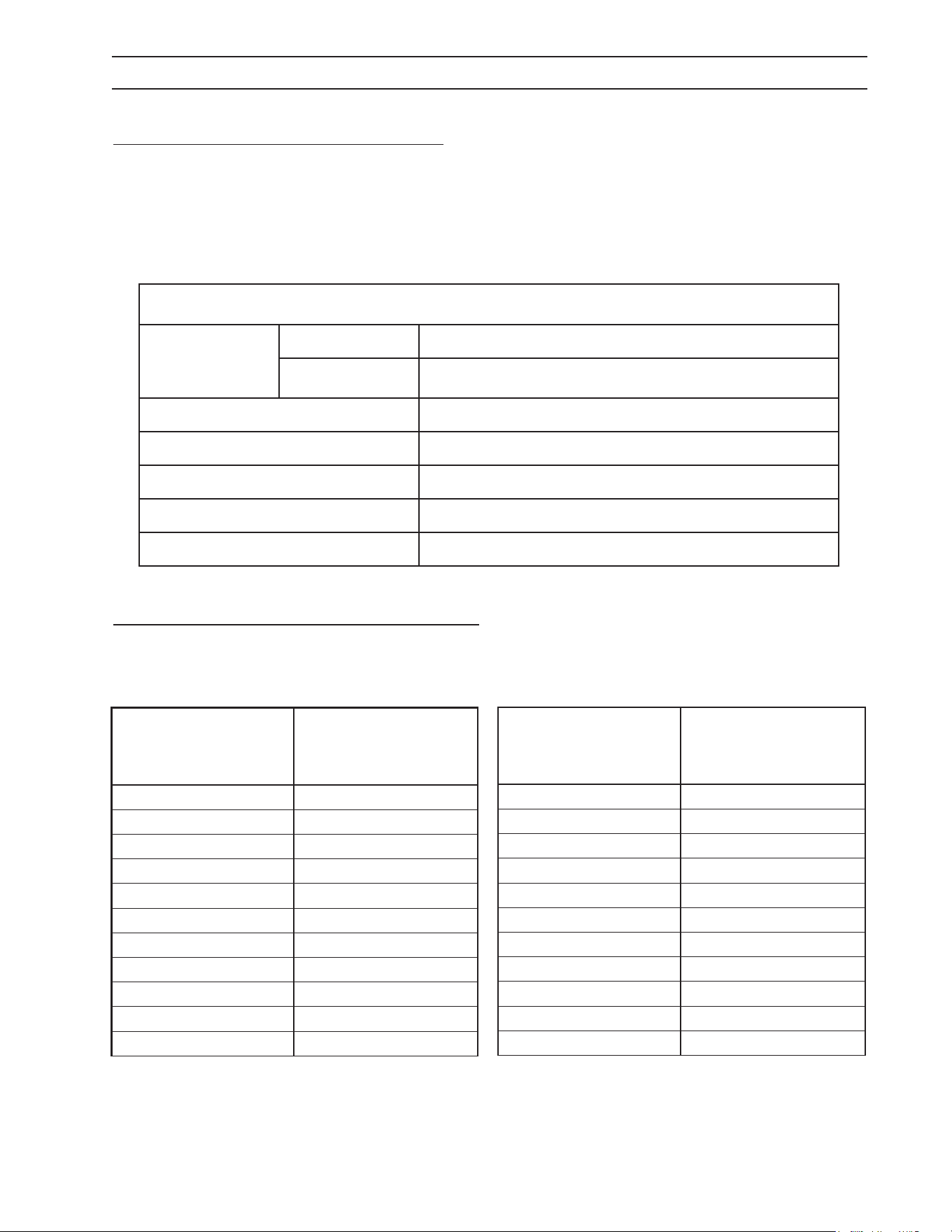
PREVENTATIVE MAINTENANCE
This pressure washer was produced with the best available materials and quality craftsmanship. However,
you as the owner have certain responsibilities for the correct care of the equipment. Attention to regular
preventative maintenance procedures will assist in preserving the performance of your equipment. Contact
your dealer for maintenance. Regular preventative maintenance will add many hours to the life of your
pressure washer. Perform maintenance more often under severe conditions.
MAINTENANCE SCHEDULE
Pump Oil
(Non foaming)
SAE 10W-40
Inspect Daily inspect the oil level
Change After rst 50 hours, then every 500 hours or annually
Replace High Pressure Nozzle Every 6 months
Replace Quick Connects Annually
Clean Water Screen/Filter Weekly
Replace HP Hose Annually if there is any sign of wear
Grease Motor Every 10,000 hours
OIL CHANGE RECORD
Check pump oil and engine oil level before rst use of your new pressure washer.
PREVENTATIVE MAINTENANCE
Date Oil Changed
Month/Day/Year
Estimated Operating
Hours Since Last
Oil Change
Date Oil Changed
Month/Day/Year
Estimated Operating
Hours Since Last
Oil Change


20
Manual Dual Mister 9.808-246.0 - J
CONTENTS
Número de modelo______________________________
Número de serie ______________________________
Fecha de compra ____________________________
Los números de modelo y de serie se encuentran en una calcomanía
adherida a la hidrolavadora. Debe registrar tanto el número de serie
como la fecha de compra, y debe guardar esta información en un lugar
seguro para referencia futura.
Manual Dual Mister 9.808-246.0 - J
21
INTRODUCCIÓN E INFORMACIÓN IMPORTANTE DE SEGURIDAD
Gracias por comprar esta lavadora a presión.
Nos reservamos el derecho de realizar cambios en
cualquier momento sin incurrir en ninguna obligación.
Responsabilidad del propietario y/o
usuario:
El propietario y/o usuario deben comprender las
instrucciones y advertencias de operación del
fabricante antes de usar esta lavadora a presión.
Se debe enfatizar y entender la información de
advertencia. Si el operador no habla inglés con
uidez, el comprador y/o propietario deberá
leer y discutir las instrucciones y advertencias
del fabricante en el idioma nativo del operador,
asegurándose de que el operador comprenda su
contenido.
El propietario y/o usuario deben estudiar y conservar
las instrucciones del fabricante para futura
referencia.
El operador debe saber cómo detener la máquina
rápidamente y comprender el funcionamiento de
todos los controles. Nunca permita que alguien opere
el motor sin las instrucciones apropiadas.
CONSERVE ESTAS INSTRUCCIONES
Este manual debe considerarse una parte
permanente de la máquina y debe permanecer
con ésta si la máquina se vuelve a vender.
Al ordenar partes, especique el modelo y el
número de serie. Utilice únicamente partes de
reemplazo idénticas.
INFORMACIÓN IMPORTANTE
DE SEGURIDAD
PRECAUCIÓN
LEA ATENTAMENTE
EL MANUAL DEL
OPERADOR ANTES
DEL USO.
OPERATIONS
SAFETY
MAINTENANCE
ADVERTENCIA: Para reducir el
riesgo de lesiones, lea
cuidadosamente las
instrucciones de operación antes
de usar.
1. Lea el manual del propietario
minuciosamente. El incumplimiento
de las instrucciones podría
ocasionar una falla de la máquina
y provocar la muerte, lesiones
corporales graves y/o daños materiales.
2. Sepa cómo detener la máquina y purgar
la presión rápidamente. Familiarícese
completamente con los controles.
3. Permanezca alerta — observe lo que está
haciendo.
4. Todas las instalaciones deben cumplir con los
códigos locales. Póngase en contacto con su
electricista, plomero, empresa de servicios
públicos o con el distribuidor de venta para
obtener detalles especícos. Si el voltaje
nominal de su máquina es 250 voltios o menos,
se suministrará corriente monofásica con un
interruptor de protección de fallas a tierra (GFCI).
Si el voltaje nominal es mayor de 250 voltios,
o más de una fase, este producto solo se debe
conectar a un receptáculo de alimentación
eléctrica protegido por un GFCI.
PELIGRO: La conexión incorrecta del conductor
de puesta a tierra del equipo puede dar como
resultado el riesgo de electrocución. Si tiene
alguna duda acerca de la puesta a tierra
adecuada del tomacorriente, consulte con un
electricista o técnico calicado. No modique el
enchufe provisto con el producto - si no encaja
en el tomacorriente, solicite a un electricista
calicado que le instale un tomacorriente
adecuado. No use ningún tipo de adaptador con
este producto
ADVERTENCIA
MANTENGA EL
ROCÍO DEL AGUA
ALEJADO DEL CA-
BLEADO ELÉCTRICO.
ADVERTENCIA: Mantenga la
varilla, la manguera y el rocío de
agua lejos del cableado eléctrico,
ya que podrían producirse
descargas eléctricas fatales.
5. Para proteger al operador
contra descargas eléctricas, la
máquina debe estar conectada
a tierra. Es responsabilidad del
propietario conectar esta máquina
a un receptáculo con puesta a tierra UL y
clasicación de voltaje y amperaje adecuados.
No rocíe agua sobre componentes eléctricos ni
cerca de los mismos. No toque la máquina con
las manos húmedas ni si está parado en una
supercie con agua. Desconecte siempre la
alimentación eléctrica antes de realizar tareas de
mantenimiento.
ADVERTENCIA
RIESGO DE EXPLOSIÓN:
OPERE SÓLO DONDE SE
PERMITE UNA LLAMA
ABIERTA O UN SOPLETE.
ADVERTENCIA: Los líquidos
inamables pueden generar
vapores que pueden encenderse
y causar daños a la propiedad o
lesiones graves.
ADVERTENCIA: Riesgo de
explosión — Opere sólo donde
se permitan llamas abiertas o
soplete.
6. No permita que ácidos, uidos cáusticos o
abrasivos pasen a través de la bomba.
7. Nunca haga funcionar la bomba en seco ni deje
la pistola rociadora cerrada por más de 1-2
minutos.
8. Mantenga el área de operación libre de
personas.
Manual Dual Mister 9.808-246.0 - J
22
INTRODUCCIÓN E INFORMACIÓN IMPORTANTE DE SEGURIDAD
ADVERTENCIA
UTILICE PROTECCIÓN
PARA LOS OJOS
Y ROPA DE
PROTECCIÓN AL O
PERAR ESTE EQUIPO
ADVERTENCIA: El rociado a alta
presión puede hacer que las
partículas de pintura u otras
partículas se transporten por aire
y vuelen a altas velocidades.
Para evitar lesiones personales,
se deben usar dispositivos de
seguridad para los ojos, manos y
pies.
9. Se debe usar protección para los ojos, las manos
y los pies al usar este equipo.
ADVERTENCIA
LA PISTOLA RE-
TROCEDE CUANDO
SE ACCIONA EL GA-
TILLO. SOSTÉNGALA
CON AMBAS MANOS.
ADVERTENCIA: Sujete la varilla
de limpieza rmemente con
ambas manos antes de
comenzar. De lo contrario, podría
sufrir lesiones a partir de un
latigueo de la varillla.
ADVERTENCIA
RIESGO DE INYECCIÓN
O LESIONES GRAVES
A LAS PERSONAS.
MANTÉNGASE ALEJADO
DE LA BOQUILLA.
ADVERTENCIA: La alta presión
desarrollada por estas máquinas
causará lesiones personales o
daños al equipo. Manténgase
alejado de la boquilla. Tenga
cuidado al operar. No dirija el
ujo de descarga a las personas,
ya que se producirán lesiones
graves o la muerte.
10. Para reducir el riesgo de lesiones, es necesaria
una estrecha supervisión cuando se utiliza
una máquina cerca de niños. No permita que
los niños operen la lavadora a presión. Esta
máquina debe ser atendida durante la
operación.
11. Nunca realice ajustes en la máquina mientras
esté en funcionamiento.
12. Asegúrese que todos los accesorios del
acoplador rápido estén asegurados antes de
usar la lavadora a presión.
ADVERTENCIA
PROTECCIÓN
CONTRA EL
CONGELAMIENTO
ADVERTENCIA: Proteja la
máquina contra congelamiento.
13. Para mantener la máquina
en las mejores condiciones de
funcionamiento, es importante
que proteja la máquina contra
congelamiento. Si no protege la
máquina contra congelamiento
podría ocasionar una falla de
la máquina y causar la muerte,
lesiones corporales graves y/o daños a
la propiedad. Siga las instrucciones de
almacenamiento especicadas en este manual.
14. El agua de entrada debe ser agua limpia y no
debe tener una temperatura superior a 90°F
(32°C).
15. El fabricante no será responsable de los
cambios realizados en nuestras máquinas
estándar o de los componentes que no se
compren a nosotros.
16. El mejor seguro contra un accidente es la
precaución y el conocimiento de la máquina.
ADVERTENCIA
RIESGO DE LESIO-
NES POR CAÍDAS
AL UTILIZAR
LA ESCALERA
ADVERTENCIA: Tenga mucho
cuidado al usar una escalera,
andamios o cualquier otra
ubicación relativamente
inestable. El área de limpieza
debe tener pendientes y drenaje
adecuados para reducir la
posibilidad de una caída debido
a las supercies resbaladizas.
17. No sobrepase ni se pare sobre un soporte
inestable. Mantenga una buena posición para los
pies y equilibrio en todo momento.
18. No opere esta máquina cuando esté fatigado
o bajo la inuencia del alcohol, medicamentos
recetados o drogas.
ADVERTENCIA
NO ROCÍE LA
MÁQUINA NI A
NINGUNA PERSONA,
ANIMALES O
PIEZAS ELÉCTRICAS.
ADVERTENCIA: No rocíe la
máquina ni a personas, animales
o piezas eléctricas.
Siga las instrucciones de mantenimiento
especicadas en el manual.
Manual Dual Mister 9.808-246.0 - J
23
PASO 1: Conecte la manguera de
½” a un balde con desinfectante (Es
recomendable que la toma de agua
esté al nivel del suelo).
Nosotros recomendamos usar Vital
Oxide.
PASO 6: Ponga la máquina en fun-
cionamianto.
PASO 5: Conecte a una fuente de
alimentación adecuada. Presione
el botón de reinicio en el interrup-
tor (GFCI).
PASO 9: Coloque la boquilla de
vaporización (mist) en la pistola
rociadora.
PASO 3: Conecte la manguera
de alta presión de ¼” al niple de
descarga. Empuje el collar del
acoplador hacia adelante hasta que
esté seguro.
PASO 7: Cierre la válvula para pur-
gar la manguera.
PASO 10: Abra la válvula para usar
en modo de vaporización.
PRECAUCIÓN: Sí la válvula per-
manece cerrada en el modo de
vaporización, la boquilla puede
dañarse.
PASO 2: Conecte la manguera
de ½” a la entrada de agua de la
bomba.
PRECAUCIÓN: No haga fun-
cionar la bomba sin agua o se
producirán daños en la bomba.
PASO 8: Purgue el aire atrapado en
la manguera (Se recomiende hacer
esto sobre el balde desinfectante).
PASO 11: Listo para su uso, bruma
(mist) Vital Oxide desinfectante.
>19”
Niple de
descarga
Manguera
de alta
presión
Collar del acoplador
PASO 4: Conecte la manguera de
alta presión a la pistola rociadora.
Pestillo de
seguridad
Pistola
rociadora
Manguera de
alta presión
Manguera
de jardín
Entrada de
agua de la
bomba
INSTRUCCIONES DE FUNCIONAMIENTO PARA
EL MODO DE VAPORIZACIÓN
IMPORTANTE: Después de ter-
minar el trabajo, elimine todos
los restos químicos de la unidad.
Llene el tanque con agua fresca
y lave todo el sistema.
Manual Dual Mister 9.808-246.0 - J
24
INSTRUCCIONES DE FUNCIONAMIENTO
PARA EL MODO DE ALTA PRESIÓN
PASO 4: Conecte la manguera de
alta presión a la pistola rociadora.
PASO 7: Cierre la válvula para
purgar la manguera.
PRECAUCIÓN: Si la válvula está
abierta, la presión no alcanzará
el nivel máximo (rate).
PASO 5: Conecte la varilla a la
pistola rociadora.
PASO 6: Jale el collar cargado por
resorte del acoplador de varilla
hacia atrás para insertar la boquilla
de presión de su elección.
PASO 1: Conecte la manguera de
½” a la entrada de agua fría.
PASO 2: Revise los ltros de en-
trada, retire los residuos y luego
conecte la manguera de jardín a la
entrada de agua de la bomba.
PRECAUCIÓN: No opere la bom-
ba sin agua o resultará en daños
a la misma.
PASO 3: Conecte la manguera
de alta presión de ¼” al niple de
descarga. Empuje el collar del
acoplador hacia adelante hasta que
esté seguro.
Pestillo de
seguridad
Pistola
rociadora
Manguera de
alta presión
Varilla
Conector
de varilla
Boquilla de alta
presión
Niple de
descarga
Manguera
de alta
presión
Fuente de
agua fría
Manguera
de jardín
Entrada de la
bomba de agua
Manguera
de jardín
Collar del acoplador
PASO 9: Ponga la máquina en fun-
cionamianto.
Pistola
rociadora
PASO 8: Conecte a una fuente de
alimentación adecuada. Presione
el botón de reinicio en el interrup-
tor (GFCI).
Manual Dual Mister 9.808-246.0 - J
25
VISTA DETALLADA DEL ENSAMBLE
9
12
11
13
26
37
25
40
41
42
43
44
45
28
29
33
27
2
3
18
7
6
34
35
5
37
10
8
9
15
14
23
22
4
16
46
1
For
Detail
See Pump
Assy
20
21
19
24
23
38
39
17
48
31
32

Manual Dual Mister 9.808-246.0 - J
26
LISTA DE PARTES DEL ENSAMBLE
PZA. NO. PARTE DESCRIPCIÓN CANT.
1 8.924-115.0 Al Base Direct Drive 1
2 8.924-394.0 Al Handle 1
3 8.924-393.0 Al Bumper 1
4 9.803-097.0 Axle, 5/8 X 20.125 Long 1
5 8.924-179.0 AL Spacer Tube DD Frame 2
6 8.756-365.0 Wheel 10" at free 1
7 9.802-782.0 Collar, 5/8" Bore Shaft 3010 2
8 9.197-003.0 3/8-16 NE Nylon Insert L/N ZC 5UM White 2
9 9.802-817.0 Washer, 3/8" x 1" 4
10 8.924-116.0 Foot AL DD Frame CW 1
11 9.802-064.0 Grommet, Rubber, Nozzle Holder 2
12 9.802-066.0 Pad Soft Rubber 2
13 9.196-041.0 Hex Head Bolt 3/8-16 X 1-3/4 2
14 8.924-074.0 Camaro Silver Axle Holder DD CW 1
15 9.802-706.0 Bolt, 1/4"-20 x 1-3/4" Carriage Zinc 8
16 9.197-010.0 1/4-20'' Nylon Insert Lock Nut With Flange 10
17 8.759-044.0 Motor 1.5HP 1PH 115/230V F3 1750RPM 56C 1
18 8.750-299.0 Unloader, VRT3, 8 GPM @4500 PSI 1
19 8.754-761.0 Pump, Leuco LF2030S, 2.1@3000, 1725RPM 1
20 9.198-004.0 3/8", USS F/W Zinc 4
21 9.802-720.0 Bolt, 3/8" x 1", NC HH 4
22 9.802-710.0 Screw 5/16" x 1" NC 4
23 8.718-980.0 Washer, 5/16" Flat, SAE 8
24 9.802-776.0 Nut, 5/16-18, ESNA 4
25 4.760-846.0 Pistol G3/8 155°C package Generic 1
26 8.783-039.0 Wand 30" Zinc Plated, Handle & Coupler 1
27 9.802-166.0 Coupler, 3/8" Socket, Female, Brass 2
28 8.925-393.0 Hose 1/4"x75' 4000 PSI SWxSW CPL S120 1
29 9.802-170.0 Coupler, 3/8" Plug, Female, Steel Zinc 1
30 8.900-305.0 Label, Landa, Home Depot, ZE Warning 1
31 9.800-037.0 Label, French Inst./Warn 1
32 9.803-834.0 Washer, Reducing 3/4" x 1/2" 1
33 9.802-169.0 Coupler, 3/8"Socket, Male, Brass 1
34 8.755-187.0 Grommet, Rubber, Nozzle Holder Base 3/16 5
35 8.712-338.0 Nozzle, SAQCMEG 1503.5, Yellow 1
8.712-339.0 Nozzle, SAQCMEG, 2503.5, Green 1
8.712-340.0 Nozzle, SAQCMEG 4003.5, White 1
36 9.800-016.0 Label, Disconnect Power Supply 1
37 8.755-210.0 Four Nozzle Label, Black 1
38 9.802-432.0 GFCI, 120V 15A, W/ 36' 12-3 CORD 1
39 8.932-969.0 Label, Warning, Service Cord 1
40 8.707-139.0 Coupler, 1/4"Plug, Male, Steel/Zinc 1
41 9.802-164.0 Coupler, 1/4"Socket, Female, Brass 1
42 8.756-030.0 Coupler, 1/4 Socket, Male, Brass 1
43 8.709-175.0 Filter,High Pressure 1/4'Npt-Fx1/4'Np 1
44 8.758-918.0 Adapter 9/16 X 1/4 1
45 8.756-697.0 Fuel Nozzle, 2.50 X 80 BZ 1
46 9.800-049.0 Label, Manufacturer's cleaning solution 1
Manual Dual Mister 9.808-246.0 - J
27
VISTA DETALLADA DE BOMBA
LISTA DE PARTES DE VISTA DETALLADA DE LA BOMBA
3
1
7
11
4
6
16
21
15
19
18
5
9
8
10
2
17
14
20
13
PZA. NO. PARTE DESCRIPCIÓN CANT.
1 8.750-299.0 Unloader, Vrt3, 8 Gpm @4500 Psi 1
2 8.757-193.0 Adapter, 1/2" F-Nptf X 1/2"
M-Nptf, Brass 1
3 8.707-152.0 Nipple, 3/8", Male, Ssteel 1
4 8.757-511.0 Elbow, 3/8", Steel 1
5 8.711-785.0 Hose, 3/8 Push On 1
6 8.758-069.0 Pump LEUCO LFP2030S,
2.1@3000, 1725RPM 1
7 8.705-119.0 Hose Barb, Elbow,
3/8"Barbx3/8"Mpt/90Deg 1
8 8.758-199.0 Hose Barb Elbow 3/8"X1/2"
90 Deg W/Slnt 1
9 8.623-315.0 Clamp, 3/8 Hose (D-Slot) 2
10 8.757-257.0 Tee, Street 1/2" 1
11 8.757-203.0 Swivel, 1/2" M-Nptf X 3/4" Ghf 1
12 9.804-016.0 Filter Screen Washer,
Garden Hose/30Mesh 1
PZA. NO. PARTE DESCRIPCIÓN CANT.
13 8.707-317.0 Valve, Flow Control 1
14 8.706-297.0 Bushing, 3/8" X 1/4"
Steel Yellow Chrom 1
15 8.706-965.0 Hose Barb, 1/4" Barb X 3/8"
Npt-M, 90 1
16 8.706-294.0 Bushing, 1/2" X 3/8",
Steel P/N-5406- 1
17 8.757-337.0 Nipple, 1/4" Close Sch 80
Steel, W/Slnt 1
18 8.757-205.0 Hose Barb, 1/4" Barb
X 1/4" M-Nptf, 90 1
19 6.390-126.0 Clamp Hose 2
20 8.758-919.0 Label Valve Label. 1
21 9.802-254.0 Hose, 1/4 Push-On 5"
Manual Dual Mister 9.808-246.0 - J
28
VISTA DETALLADA DEL FILTRO
LISTA DE PARTES DEL FILTRO
PZA DESCRIPCIÓN CANT.
1 Housing, Nozzle Filter, 1/4 NPT-F 1
2 Retainer, Filter 1
3 Screen, 100 Mesh, T304SS 1
4 O-Ring, 70 Duro, Buna-N, .426 ID x .070 CS 1
5 Outlet Fitting, Nozzle Filter, 1/4 NTP-M 1
6 Retainer, External, SS 1
1
6
2
3
4
5
Manual Dual Mister 9.808-246.0 - J
29
LIMPIEZA DEL FILTRO DE ENTRADA DE AGUA
PASO 2: Saque el ltro de entrada
de agua.
Utiliza las herramientas necesar-
ias.
PASO 4: Montar el ltro de en-
trada de agua. Utiliza las herra-
mientas necesarias.
PASO 1: Desconecte la boquilla
de pulverización de la máquina.
PASO 3: Enjuague el filtro
de entrada de agua en agua
tibia.
Filtro
Filtro
Manual Dual Mister 9.808-246.0 - J
30
VISTA DETALLADA DE LA BOMBA LF 2030S
LISTA DE PARTES DE LA BOMBA LF 2030S
13
6
8
1
3
9
10
11
12
13
14
15
21
20
17
16
12
14
15
22
23
24
25
26
27
28
31
32
33
35
39
40
41
42
43
45
44
37
46
47
48
26
2
5
7
18
19
29
30
34
36
38
49
4
37
50
21
PZA. NO. PARTE DESCRIPCIÓN CANT.
19 8.754-850.0 Washer, Lock 2
20 9.803-198.0 Washer, Copper G3/8 1
21 8.707-262.0 Plug, Brass G3/8 2
22* Ver Kits Abajo Valve Seat 6
23* Ver Kits Abajo Valve Plate 6
24* Ver Kits Abajo Valve Spring 6
25* Ver Kits Abajo Valve Cage 6
26 9.802-939.0 Screw, M6 X 16 8
27 8.717-137.0 Bearing Cover 1
28 9.803-954.0 Bearing Seal 1
29 8.754-843.0 Seal Spacer, Crankshaft 1
30 9.802-914.0 Snap Ring, 25 mm 1
31 9.803-955.0 Bearing, Ball 1
32 8.754-836.0 Shaft, 5/8" Hollow 1
33 8.754-219.0 Oil Dipstick 1
34 8.754-840.0 Bearing Needle 1
35 8.754-826.0 Seal, Crankshaft 1
36 8.754-844.0 Flange, Motor 1
37 9.803-210.0 Washer 10
38 8.752-824.0 Screw, 6 mm 4
PZA. NO. PARTE DESCRIPCIÓN CANT.
1 8.754-841.0 Crankcase 1
2 8.754-846.0 O-ring Ø1.78 X 72.75 1
3* Ver Kits Abajo Plunger Oil Seal 3
4* Ver Kits Abajo O-ring Ø1.78 X 26.7 3
5* Ver Kits Abajo Washer, Pressure Ring 3
6* Ver Kits Abajo U-Seal 3
7* Ver Kits Abajo Pressure Ring 3
8* Ver Kits Abajo U-Seal 3
9 9.803-199.0 Washer, Copper G1/2 1
10 9.802-926.0 Plug, Brass G1/2 1
11 8.754-852.0 Manifold (16mm Modelos) 1
8.754-853.0 Manifold (14mm Modelos) 1
12* 8.717-233.0 O-ring Ø1.78 X 15.6 6
13* See Kits Below Valve Assembly 6
14* 9.803-948.0 O-ring Ø1.78 X 18.77 6
15 9.803-949.0 Valve Plug 6
16 8.754-851.0 Plug, Brass G1/4 (16mm) 1
17 8.754-845.0 Washer, Copper G1/4
(16mm Models) 1
18 8.754-854.0 Bolt, Manifold M14 X 40 2
ESPECIF. DE
TORQUE
Elem # Ft.-lbs
15 65
18 55
26 8
38 10
39 10
46 10
8.924-736.0 LF 2030S
Manual Dual Mister 9.808-246.0 - J
31
PZA. PARTE NO. DESCRIPCIÓN CANT.
39* 8.754-855.0 Bolt, Plunger 3
40* 8.754-092.0 Spacer, Copper 3
41 8.754-848.0 Plunger, 16mm 3
42 9.803-962.0 Spacer, Copper 3
43 8.754-827.0 Plunger Rod 3
44 9.803-965.0 Connecting Rod Pin 3
45 9.803-966.0 Connecting Rod 3
46 8.933-020.0 Screw, Connecting Rod 6
47 8.754-847.0 O-ring Ø2.62 X 111.62 1
48 8.754-842.0 Cover, Crankcase 1
49 9.803-906.0 O-ring Ø1.78 X 14 1
50 9.803-202.0 Sight Glass, G3/4 1
NÚMERO DE EQUIPO DE
REPARACIÓN 8.754-860.0 8.754-856.0 8.754-861.0 8.754-857.0 8.754-862.0 8.754-858.0 8.754-859.0 9.803-937.0
DESCRIPCIÓN DEL
EQUIPO
Plunger
Seals
14 mm**
Plunger
Seals 16
mm**
Seal Pack-
ing
14 mm**
Seal Pack-
ing
16
mm**
Plunger
14 mm**
Plunger
16 mm**
Complete
Valve
Plunger Oil
Seals
NÚMEROS DE ARTÍCULO
INCLUIDO
4, 6, 8 4, 6, 8 4, 5, 6, 7, 8 4, 5, 6, 7, 8
39, 40, 41,
42
39, 40, 41,
42
12, 13, 14 3
LISTA DE PARTES DE LA BOMBA LF 2030S
Manual Dual Mister 9.808-246.0 - J
32
VISTA DETALLADA DEL DESCARGADOR VRT3
9
8
23
26
3
16
1
10
24
11
6
4
13
14
20
25
12
22
19
15
2
15
21
17
7
9
5
6
8.750-299.0, 8 GPM, 4500 PSI
PZA. NO. PARTE DESCRIPCIÓN CANT.
25 8.750-712.0 Outlet Fitting 1
8.750-709.0 Repair Kit, VRT3, 2320/3630
PSI
8.750-710.0 Repair Kit, VRT3, 4500 PSI
(Kit piezas: 1, 4, 8-12, 16, 21-22)
Procedimientos de ajuste del descargador
1. Retirar contratuerca (Componente 19)
2. Aojar las dos tuercas (Componente 15) y desplazar hacia la parte superior del eje (Componente 8) hasta que 4 o más hilos de la
roca sean visibles bajo la tuerca.
3. Encender máquina. Presionar gatillo de la pistola rociadora. Incrementar la presión girando la en sentido de las manecillas del
reloj hasta obtener la presión deseada.
4. Apretar la tuerca inferior (Componente 15) contra la tuerca superior (Componente 15).
Atornillar contratuerca (Componente 19) al eje (Componente 8) hasta que las roscas corten el inserto de nylon de esta (Componente
19).
** Suelte el gatillo de la pistola rociadora, observar el manómetro durante el aumento de la presión (“pico”), este NO debe de exceder
los 500 PSI por encima de la presión de operación. Si esta presión excede los el límite de 500 PSI, vuelva a ajustar las tuercas
(Componente 15) desplazándolas hacia abajo del eje (Componente 8), una vez terminada esta operación, es necesario repetir el paso
4.
Manual Dual Mister 9.808-246.0 - J
33
DIAGRAMA DE CABLEADO
BOMBA
MOTOR
INTERRUPTOR
DE PALANCA
INTERRUPTOR DE PALANCA UBICADO EN
LA CAJA ELÉCTRICA DEL MOTOR.
TODOS LOS CABLES NEGROS A MENOS QUE SE INDIQUE
G - VERDE
W - BLANCO
1.106-160.0 HD 2.0/1000 Dual Mister
Manual Dual Mister 9.808-246.0 - J
34
SOLUCIÓN DE PROBLEMAS
PROBLEMA CAUSA POSIBLE SOLUCIÓN
BOMBA
FUNCIONANDO
NORMALMENTE
PEROPRESIÓN BAJA
EN INSTALACIÓN
La bomba está aspirando aire
Compruebe el suministro de agua y la posibilidad
de inltración de aire.
Válvulas adheridas Revise y limpie o reemplace si es necesario.
El asiento de la válvula del descargador
está defectuoso
Revise y reemplace si es necesario.
Boquilla de tamaño incorrecto Revise y reemplace si es necesario.
Empaque de pistón desgastado Revise y reemplace si es necesario.
PRESIÓN
FLUCTUANTE
Válvulas de bomba gastadas Revise y reemplace si es necesario.
Bloqueo en la válvula Revise y reemplace si es necesario.
La bomba succiona aire Revise las conexiones de suministro de agua.
Empaque de pistón desgastado Revise y reemplace si es necesario.
Suministro de agua insuciente Compruebe si el ltro y la manguera están rotos.
PRESIÓN BAJA
DESPUÉS DEL
PERÍODO DE USO
NORMAL
Boquilla gastada Revise y reemplace si es necesario.
Válvulas de succión o suministro desgasta-
das
Revise y reemplace si es necesario.
Líneas de succión o suministro bloqueadas Revise y limpie si es necesario.
La válvula del descargador está desgastada Revise y reemplace si es necesario.
Empaque de pistón desgastado Revise y reemplace si es necesario.
Temperatura del agua excesiva Reducir a menos de 160
o
F (71.11
o
C)
LA BOMBA ES
RUIDOSA
Aire en la línea de succión
Verique el suministro de agua y las conexiones
en la línea de succión.
Resorte de la válvula de succión o suminis-
tro roto o débil
Revise y reemplace si es necesario.
Materia extraña en válvula Revise y limpie si es necesario.
Cojinetes desgastados Revise y reemplace si es necesario.
Temperatura del agua excesiva Reducir a menos de 160
o
F (71.11
o
C)
PRESENCIA DE
AGUA EN ACEITE DE
BOMBA
Sello de aceite desgastado Revise y reemplace si es necesario.
Alta humedad en el aire Revise y reemplace si es necesario.
Empaque de pistón desgastado Revise y reemplace si es necesario.
GOTEO DE AGUA EN
LA PARTE INFERIOR
DE LA BOMBA
Empaque de pistón desgastado Revise y reemplace si es necesario.
Anillo O del retén del émbolo desgastado Revise y reemplace si es necesario.
GOTEO DE AGUA
DESDE EL
PROTECTOR DE
BOMBA
Presión de suministro de agua demasiado
alta (más de 90 PSI)
Reduzca la presión del suministro de agua con un
regulador.
La pistola rociadora está en la posición de
apagado, por más de 5 minutos.
Apague la máquina si no la usa por más de 1-2
minutos.
GOTEO DE ACEITE
Sello de aceite desgastado Revise y reemplace si es necesario.
VIBRACIÓN EXCE-
SIVA EN MANGUERA
DE ALTA PRESIÓN
Funcionamiento irregular de las válvulas de
la bomba
Revise y reemplace si es necesario.
EL MOTOR NO
ARRANCA CUANDO
SE ENCIENDE
Enchufe no bien conectado o falta de
corriente eléctrica.
Compruebe el enchufe, el cable y el interruptor.
AL ENCENDER LA
MÁQUINA, EL MO-
TOR HUME PERO NO
FUNCIONA
El voltaje principal es insuciente, más bajo
que el mínimo requerido
Compruebe que la fuente de alimentación princi-
pal sea la adecuada.
La bomba está atascada o congelada Verique girando el motor manualmente.
MOTOR DETENIDO
Sobrecarga térmica disparada debido a
sobrecalentamiento
Verique que la tensión principal corresponda con
las especicaciones. Espere unos minutos antes
de volver a encender la máquina reiniciando el
cable GFCI.
Manual Dual Mister 9.808-246.0 - J
35
MANTENIMIENTO PREVENTIVO
Esta lavadora a presión fue producida con los mejores materiales disponibles y mano de obra de calidad.
Sin embargo, usted como propietario tiene ciertas responsabilidades para el cuidado correcto del equipo.
La atención a los procedimientos regulares de mantenimiento preventivo ayudará a preservar el desempeño
de su equipo. Póngase en contacto con su distribuidor para el mantenimiento. El mantenimiento preventivo
regular agregará muchas horas a la vida útil de su lavadora a presión. Realice el mantenimiento más a
menudo en condiciones severas.
REGISTRO DE CAMBIO DE ACEITE
Verique el aceite de la bomba y el nivel del aceite del motor antes de usar por primera vez su nueva lavadora
a presión.
Fecha de cambio de
aceite de la bomba
Mes/Día/Año
Horas de funcio-
namiento estimadas
desde el último
cambio de aceite
Fecha de cambio de
aceite de la bomba
Mes/Día/Año
Horas de funcio-
namiento estimadas
desde el último
cambio de aceite
PROGRAMA DE MANTENIMIENTO
Aceite de bomba
(Anti-espuma)
SAE 10W-40
Revisar Nivel de aceite Diario o cada uso
Cambiar
Después de las primeras 50 horas, y después cada 500
horas o anualmente.
Reemplace la boquilla de alta presión Cada 6 meses
Reemplace las conexiones rápidas Anualmente
Limpie la pantalla y el ltro de agua Semanalmente
Reemplazar manguera HP Anualmente (si hay cualquier señal de desgaste)
Grease Motor Every 10,000 hours
MANTENIMIENTO PREVENTIVO
Registrieren Sie Ihr Prudukt und Sie von vielen Vorteilen.
Register your product and benefit from many advantages.
Enregistrez votre produit et bénéficiez de nombreux avantages.
Registre su producto y aproveche de muchas ventajas.
Bewerten Sie Ihr Produkt und sagen Sie uns Ihre Meinung.
Rate your product and tell us your opinion.
Évaluez votre produit et donnez-nous votre opinion.
Reseña su producto y díganos su opinión.
www.kaercher.com/welcome
www.kaercher.com/dealersearch
Kärcher North America
6398 N Kärcher Way
Aurora, CO 80019
Phone: +1 800 444-7654
DANKE!
THANK YOU!
MERCI!
GRACIAS!
!