PHONE HOLDER
LEVEL FOOT
LOCK NUT(L/R)
WASHER 10
Φ
WASHER 8
Φ
DOMED NUT M8
PHONE HOLDER
LEVEL FOOT
LOCK NUT(L/R)
WASHER 10
Φ
WASHER 8
Φ
DOMED NUT M8
Φ
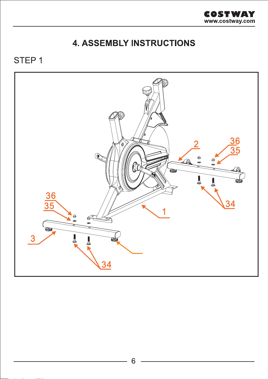
a. Attach Front Stabilizer (2) to Main Frame (1) using 2pcs of CARRIAGE BOLT (34),
2pcs of WASHER 8 (35) and 2pcs of DOMED NUT M8 (36).
13
b. Repeat step a to install Rear Stabilizer (3) to Main Frame (1).
c. Lever the machine
The user can tighten or loosen 4 x LEVEL FOOT (13) to level the machine if needed.
Tighten 4 x LEVEL FOOT (13) to make the machine stable before starting workout.
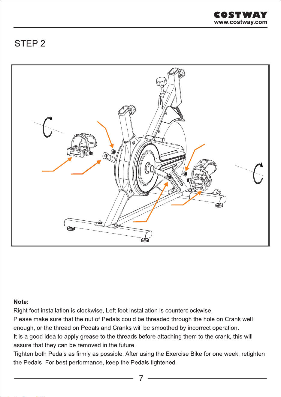
a. A pair of Pedals (23/ 24) has a sign, "L" is the left pedal, and "R" is the right pedal.
b. Loosen nuts on Pedals (23/ 24). Connect Pedals (23/ 24) to Cranks (21/ 22) as shown in
above diagram.
C.Then fixing them with two nuts(15 ).
23
22
21
24
Clockwise
Anti-Clockwise
15
15
Φ
a. Attach Front Stabilizer (2) to Main Frame (1) using 2pcs of CARRIAGE BOLT (34),
2pcs of WASHER 8 (35) and 2pcs of DOMED NUT M8 (36).
13
b. Repeat step a to install Rear Stabilizer (3) to Main Frame (1).
c. Lever the machine
The user can tighten or loosen 4 x LEVEL FOOT (13) to level the machine if needed.
Tighten 4 x LEVEL FOOT (13) to make the machine stable before starting workout.
a. A pair of Pedals (23/ 24) has a sign, "L" is the left pedal, and "R" is the right pedal.
b. Loosen nuts on Pedals (23/ 24). Connect Pedals (23/ 24) to Cranks (21/ 22) as shown in
above diagram.
C.Then fixing them with two nuts(15 ).
23
22
21
24
Clockwise
Anti-Clockwise
15
15
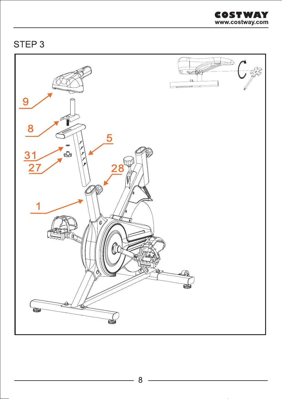
a. Loosen PULL PIN KNOB (28)
and pull out, insert Seat Post (5)
into the rear opening tube of
the Main Frame (1). Adjust the
Seat Post (5) to your desired
height, then tighten the PULL
PIN KNOB (28).
b. Place Seat Slider (8) onto Seat
Post (5), then fix them with
WASHER 10 (31) and
OCTAGONAL KNOB (27).
c. Place Seat (9) onto Seat
Slider (8), secure seat by
tightening the seat locking nuts
(Pre-fitting on the Seat).
Φ
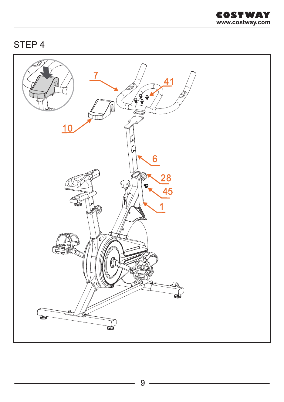
a. Insert Handlebar Post (6)
into the front opening tube
of the Main Frame (1).
Tighten PULL PIN KNOB (28)
and Fixing Knob (45).
b. Attach Handlebar (7) onto
Handlebar Post (6) with
4 sets of M8 SCREW (41).
Then place the Phone Holder
(10) on Handlebar (7),
and press it down.
a. Loosen PULL PIN KNOB (28)
and pull out, insert Seat Post (5)
into the rear opening tube of
the Main Frame (1). Adjust the
Seat Post (5) to your desired
height, then tighten the PULL
PIN KNOB (28).
b. Place Seat Slider (8) onto Seat
Post (5), then fix them with
WASHER 10 (31) and
OCTAGONAL KNOB (27).
c. Place Seat (9) onto Seat
Slider (8), secure seat by
tightening the seat locking nuts
(Pre-fitting on the Seat).
Φ
a. Insert Handlebar Post (6)
into the front opening tube
of the Main Frame (1).
Tighten PULL PIN KNOB (28)
and Fixing Knob (45).
b. Attach Handlebar (7) onto
Handlebar Post (6) with
4 sets of M8 SCREW (41).
Then place the Phone Holder
(10) on Handlebar (7),
and press it down.
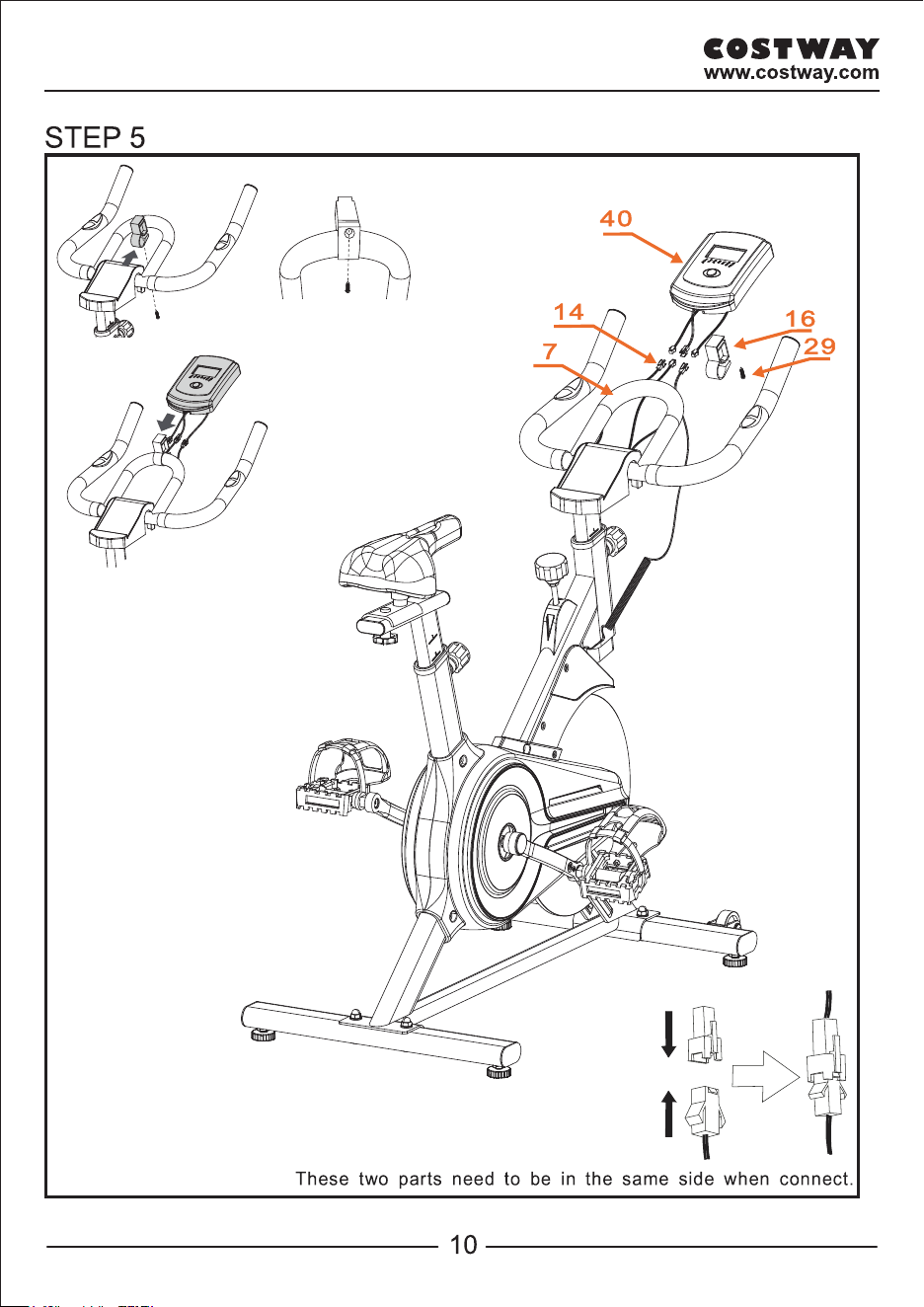
Attach the Monitor Post
(16) to Handlebar (7),
fix it by Screw (29).
Insert Monitor (40) into
Monitor Post (16). Then
connect the Sensor Wire
(14) from Monitor (40)
to the Sensor Wire (14)
from Main Frame (1) and
Handlebar (7)
13
28
27
28
45
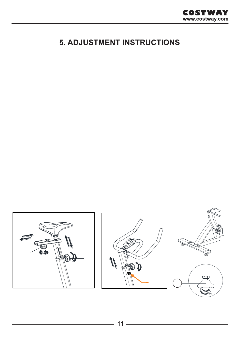
Vertical Seat Adjustment
To adjust the seat height, slacken Pull Pin Knob on the vertical post stem on the main frame and
pullback the knob. Position the vertical seat post for the desired height so that holes are aligned,
then release the knob and retighten it.
Horizontal Seat Adjustment
To move the seat forward in the direction of the handlebar or backwards away from it, loosen the
O ctagonal Knob and washer and pull the knob back. Slide horizontal seat post into desired position.
Align holes and then retighten the O ctagonal Knob.
Handlebar Height
To adjust the handlebar height, slacken Pull Pin Knob and F ix ing Knob and pull both knobs
back. Slide the handlebar post along the housing on the main frame to the desired height and,
with the holes aligned correctly, tighten the Pull Pin Knob and then the F ix ing Knob.
LEVEL ADJUSTMENT
To adjust Level Foot (13), so the stabilizers are level to the floor. Rotate the Level Foot (13)
clockwise or counter-clockwise to adjust the level of the bike.
Attach the Monitor Post
(16) to Handlebar (7),
fix it by Screw (29).
Insert Monitor (40) into
Monitor Post (16). Then
connect the Sensor Wire
(14) from Monitor (40)
to the Sensor Wire (14)
from Main Frame (1) and
Handlebar (7)
13
28
27
28
45
Vertical Seat Adjustment
To adjust the seat height, slacken Pull Pin Knob on the vertical post stem on the main frame and
pullback the knob. Position the vertical seat post for the desired height so that holes are aligned,
then release the knob and retighten it.
Horizontal Seat Adjustment
To move the seat forward in the direction of the handlebar or backwards away from it, loosen the
O ctagonal Knob and washer and pull the knob back. Slide horizontal seat post into desired position.
Align holes and then retighten the O ctagonal Knob.
Handlebar Height
To adjust the handlebar height, slacken Pull Pin Knob and F ix ing Knob and pull both knobs
back. Slide the handlebar post along the housing on the main frame to the desired height and,
with the holes aligned correctly, tighten the Pull Pin Knob and then the F ix ing Knob.
LEVEL ADJUSTMENT
To adjust Level Foot (13), so the stabilizers are level to the floor. Rotate the Level Foot (13)
clockwise or counter-clockwise to adjust the level of the bike.
-clip to
-clip to