0
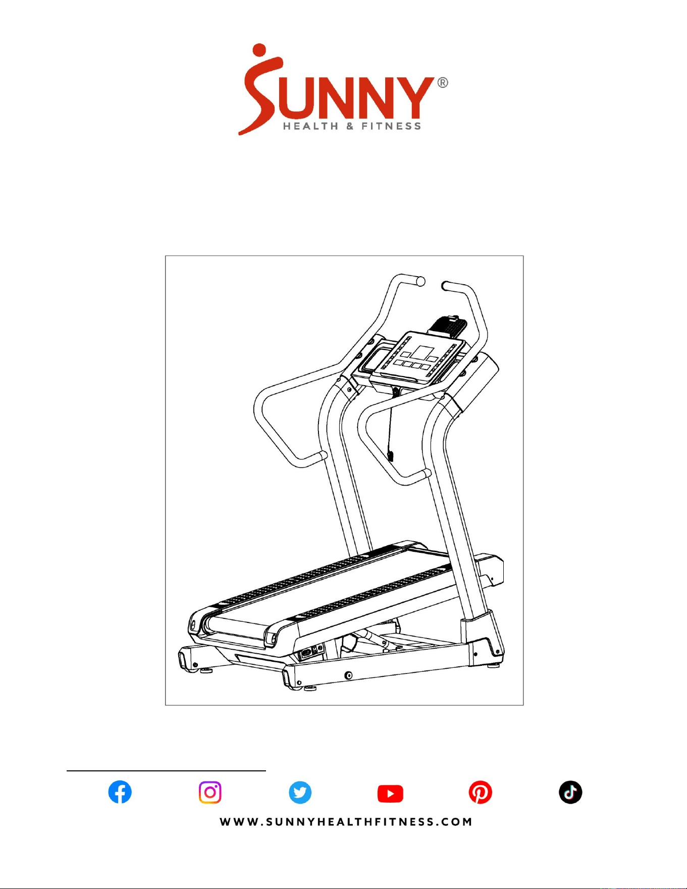
PREMIUM INCLINE TREADMILL
SF-X7200
USER MANUAL
IMPORTANT! Please retain owner’s manual for maintenance and adjustment instructions. Your
satisfaction is very important to us, PLEASE DO NOT RETURN UNTIL YOU HAVE CONTACTED
US: [email protected] or 1-877-90SUNNY (877-907-8669).

1
IMPORTANT SAFETY INSTRUCTIONS
We thank you for choosing our product. To ensure your safety and health, please use this equipment
correctly. It is important to read this entire manual before assembling and using the equipment. Safe
and effective use can only be achieved if the equipment is assembled, maintained, and used properly.
It is your responsibility to ensure that all users of the equipment are informed of all warnings and
precautions.
1. Before starting any exercise program, you should consult your physician to determine if you have
any medical or physical condition that could put your health and safety at risk or prevent you from
using the equipment properly. Your physician’s advice is essential if you are taking medication that
affects your heart rate, blood pressure or cholesterol level.
2. Be aware of your body’s signals. Incorrect or excessive exercise can damage your health. Stop
exercising if you experience any of the following symptoms: pain, tightness in your chest, irregular
heartbeat, shortness of breath, lightheadedness, dizziness, or feelings of nausea. If you do
experience any of these conditions, you should consult your physician before continuing with your
exercise program.
3. Keep children and pets away from the equipment. The equipment is designed for adult use only.
4. Use the equipment on a solid, flat level surface with a protective cover for your floor or carpet. To
ensure safety, the equipment should have at least 8 feet (240 cm) of free space behind it and 2
feet (60 cm) on each side. Do not place the treadmill on any surface that blocks air openings. To
protect the floor or carpet from damage, place a mat under the treadmill.
5. Ensure that all nuts and bolts are securely tightened before using the equipment. The safety of the
equipment can only be maintained if it is regularly examined for damage and/or wear and tear.
6. Always use the equipment as indicated. If you find any defective components while assembling or
checking the equipment, or if you hear any unusual noises coming from the equipment during
exercise, discontinue use of the equipment immediately and do not use until the problem has
been rectified.
7. Wear suitable clothing while using the equipment. Avoid wearing loose clothing that may become
entangled in the equipment.
8. Do not place fingers or objects into the moving parts of the equipment.
9. The maximum weight capacity of this unit is 330 lbs (150 kgs).
10. The equipment is not suitable for therapeutic use.
11. To avoid bodily injury and/or damage to the product or property, proper lifting and moving are
required.
12. Your product is intended for use in cool, dry conditions. You should avoid storage in extremely
cold, hot, or damp areas as this may lead to corrosion and other related problems.
13. This equipment is designed for indoor and home use only, it is not intended for commercial use!

2
IMPORTANT SAFETY INSTRUCTIONS
When using an electrical appliance, basic precautions should always be followed, including the
following:
Read all instructions before using (this appliance).
DANGER – To reduce the risk of electric shock and the injury from moving parts:
Always unplug this appliance from the electrical outlet immediately after using and before cleaning or
servicing.
WARNING – To reduce the risk of burns, fire, electric shock, or injury to persons:
1) An appliance should never be left unattended when plugged in. Unplug from outlet when not in
use, and before putting on or taking off parts.
2) This appliance is not intended for use by persons with reduced physical, sensory, or mental
capabilities, or lack of experience and knowledge, unless they have been given supervision or
instruction concerning use of the appliance by a person responsible for their safety. Keep children
under the age of 13 away from this machine.
3) Use this appliance only for its intended use as described in this manual. Do not use attachments
not recommended by the manufacturer.
4) Never operate this appliance if it has a damaged cord or plug, if it is not working properly, if it has
been dropped or damaged, or dropped into water. Return the appliance to a service center for
examination and repair.
5) Do not carry this appliance by supply cord or use cord as a handle.
6) Keep the cord away from heated surfaces.
7) Never operate the appliance with the air openings blocked. Keep the air openings free of lint, hair,
and the like.
8) Never drop or insert any object into any opening.
9) Do not use outdoors. Household use only.
10) Do not operate where aerosol (spray) products are being used or where oxygen is being
administered.
11) To disconnect, turn all controls to the off position, then remove plug from outlet.
12) CAUTION: Risk of Injury to Persons – To Avoid Injury, use extreme caution when stepping onto or
off of a moving belt. Read Instruction Manual Before Using.
13) Connect this appliance to a properly grounded outlet only. See Grounding Instructions.
14) REMOVE CONTROL BOX (OR KEY, OR SAFETY PIN, AS APPLICABLE) WHEN NOT IN USE,
AND STORE OUT OF REACH OF CHILDREN.
SAVE THESE INSTRUCTIONS
IMPORTANT NOTE:
The belt must be lubricated before the first use! Please see Page 8 for instructions on how to
properly apply lubricant.
3
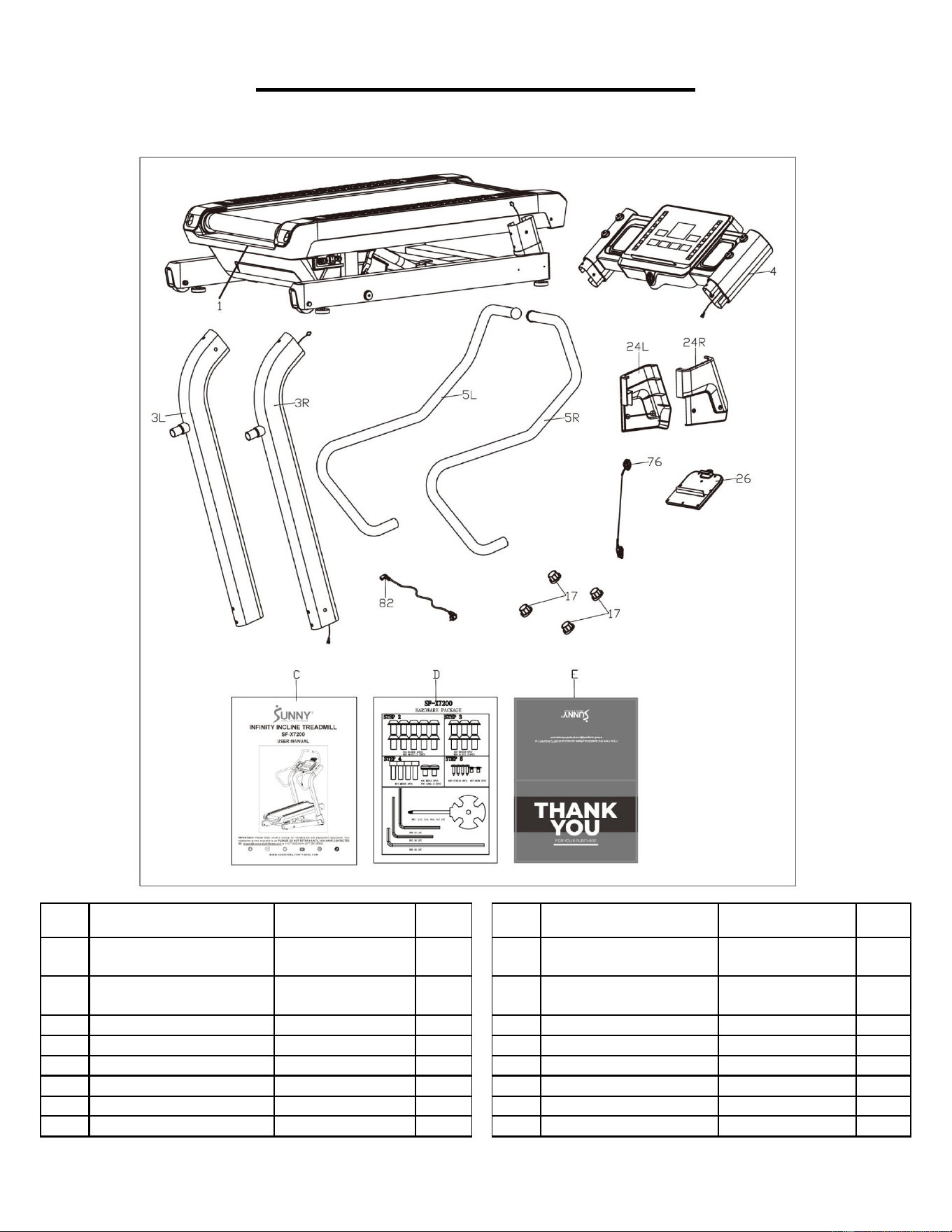
PRE-ASSEMBLY CHECK LIST
Before you start to assemble, please make sure all parts are included.
No.
Description
Spec.
Qty.
No.
Description
Spec.
Qty.
1
Main Frame
1
24R
Right Upright Tube
Cover
203.5X64.7X254
1
3L
Left Upright Tube
1
26
Tablet Holder Upper
Cover
220X170X8.6
1
3R
Right Upright Tube
1
76
Safety Key
1
4
Console Support
1
82
Power Cord
2000MM
1
5L
Left Handrail
1
C
Manual
1
5R
Right Handrail
1
D
Hardware Package
1
17
End Cap
Φ23.6X15.2
4
E
Thank You Card
1
24L
Left Upright Tube Cover
203.5X64.7X254
1
4
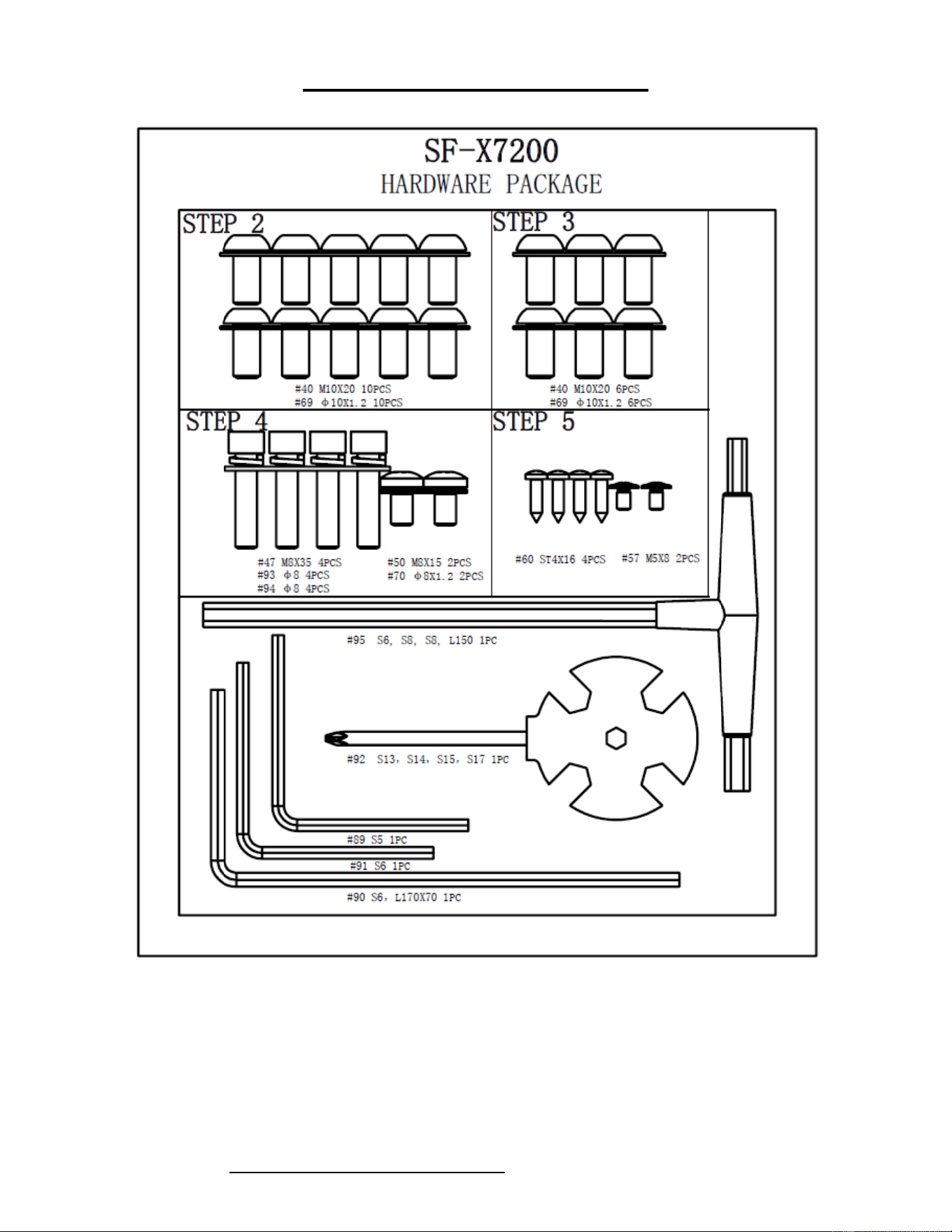
HARDWARE PACKAGE
Ordering Replacement Parts (U.S. and Canadian Customers only)
Please provide the following information in order for us to accurately identify the part(s) needed:
✓ The model number (found on cover of manual)
✓ The product name (found on cover of manual)
✓ The part number found on the “EXPLODED DIAGRAM” (page 17) and “PARTS LIST” (pages
18-19)
Please contact us at [email protected] or 1-877-90SUNNY (877-907-8669).
5
ASSEMBLY INSTRUCTIONS
We value your experience using Sunny Health and Fitness products. For assistance with parts or
troubleshooting, please contact us at suppo[email protected] or 1-877-90SUNNY (877-907-
8669).
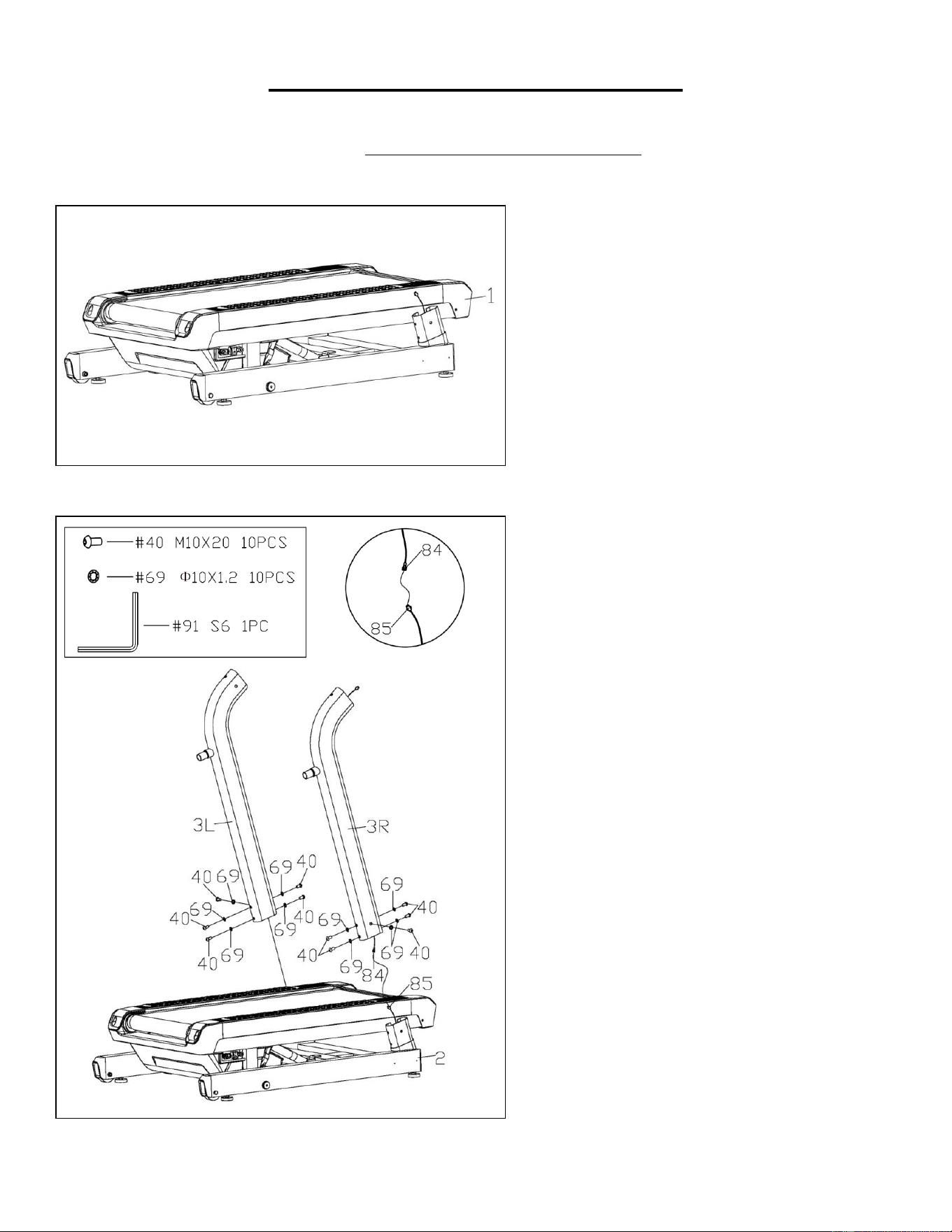
STEP 1:
We recommend having two people to do
the assembly.
Open the carton and remove contents.
Place the Main Frame (No. 1) on level
ground and ensure you have a clean and
adequate workspace.
STEP 2:
Connect the Console Middle Cable (No.
84) with the Console Lower Cable (No.
85).
Pre-secure the Left and Right Upright
Tubes (No. 3L & No. 3R) to the Bottom
Support (No. 2) with 10 Inner Hex Bolts
(No. 40) and 10 Serrated Lock Washers
(No. 69) using Allen Wrench (No. 91).
NOTE: Please do not completely tighten
the Inner Hex Bolts (No. 40) at this step.
NOTE: Be careful not to cut or pinch any
cables when attaching the Left and Right
Upright Tubes (No. 3L & No. 3R).
6
We value your experience using Sunny Health and Fitness products. For assistance with parts or
troubleshooting, please contact us at suppo[email protected] or 1-877-90SUNNY (877-907-
8669).
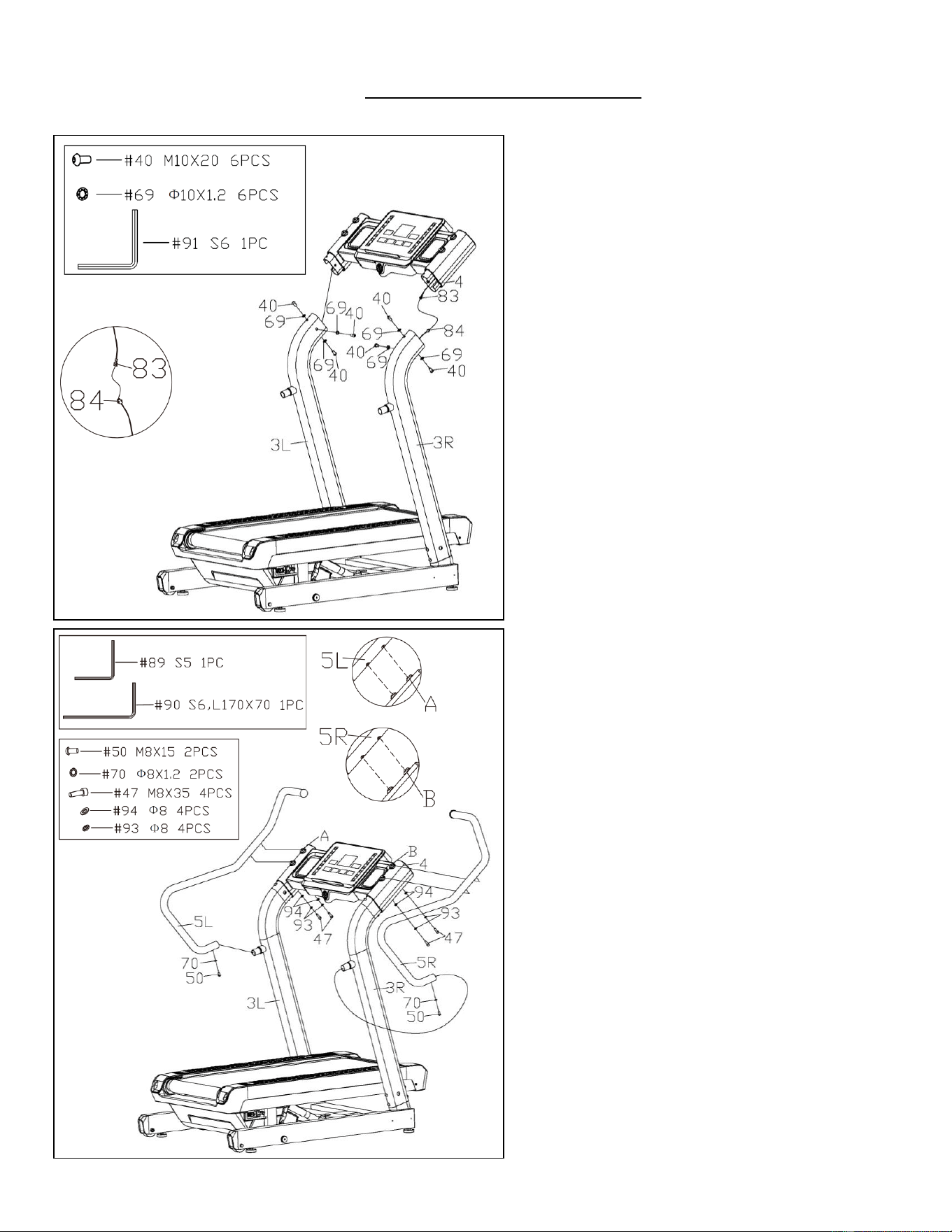
STEP 3:
Connect the Console Upper Cable (No.
83) to the Console Middle Cable (No.
84).
Fasten the Console Support (No. 4) to
the Left and Right Upright Tubes (No.
3L & No. 3R) with 6 Inner Hex Bolts (No.
40) and 6 Serrated Lock Washers (No.
69) using Allen Wrench (No. 91).
NOTE: Be careful not to cut or pinch any
cables when attaching the Console
Support (No. 4).
STEP 4:
Insert the Left and Right Handrails (No.
5L & No. 5R) onto the connecting tubes of
the Left and Right Upright Tubes (No.
3L & No. 3R). Pre-secure with 2 Inner
Hex Flat Head Bolts (No. 50) and 2
Serrated Lock Washers (No. 70) using
Allen Wrench (No. 89).
NOTE: Please do not completely tighten
Inner Hex Flat Head Bolts (No. 50) now.
Align the corresponding holes on Left and
Right Handrails (No. 5L & No. 5R) with
the holes A and B located on the Console
Support (No. 4). Fasten the Left and
Right Handrails (No. 5L & No. 5R) to the
Console Support (No. 4) together with 4
Socket Head Cap Bolts (No. 47), 4
Spring Washers (No. 93) and 4 Flat
Washers (No. 94) using Allen Wrench
(No. 90).
7
We value your experience using Sunny Health and Fitness products. For assistance with parts or
troubleshooting, please contact us at suppo[email protected] or 1-877-90SUNNY (877-907-
8669).
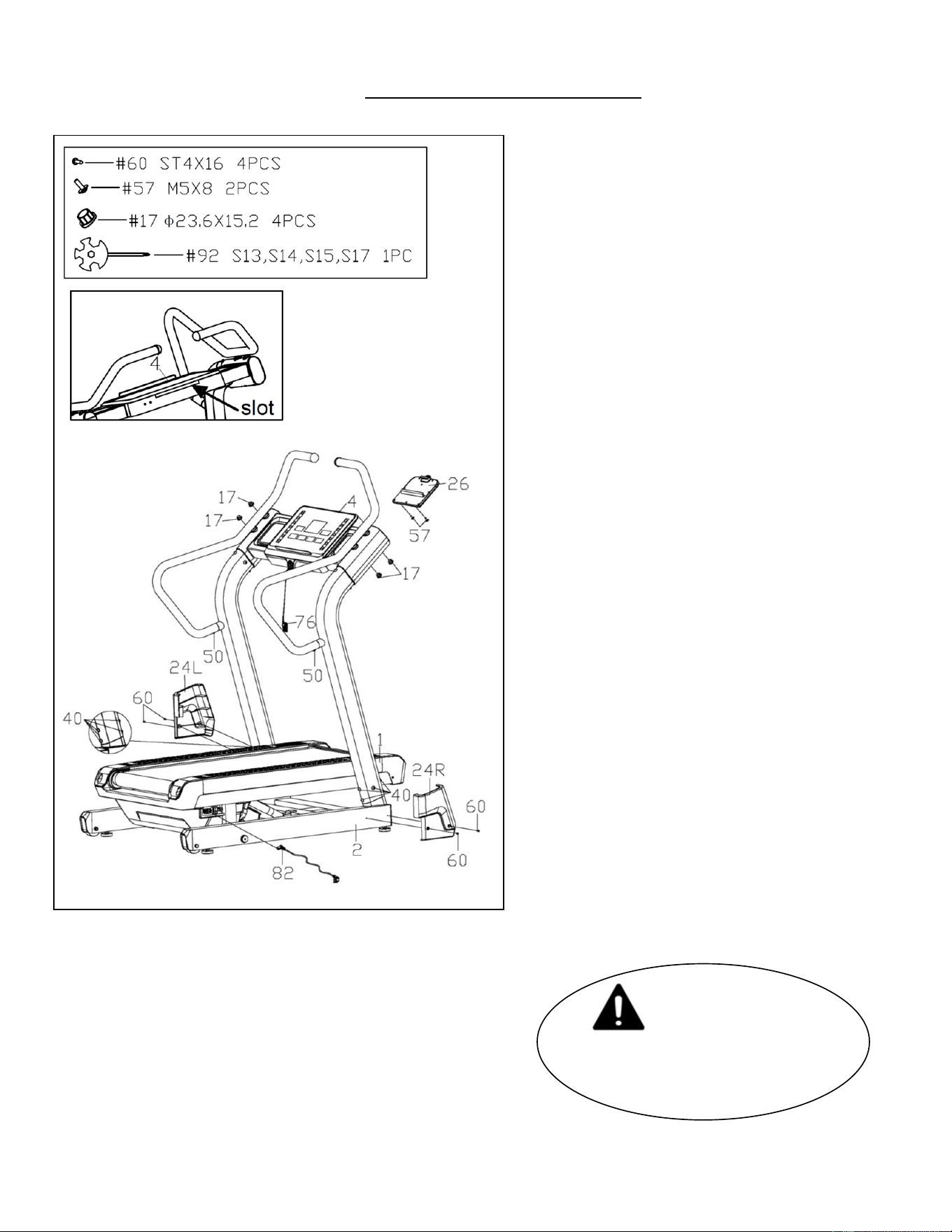
STEP 5:
First, fasten the 10 Inner Hex Bolts (No.
40) from STEP 2 tightly using Allen
Wrench (No. 91).
Then, fasten the 2 Inner Hex Flat Head
Bolts (No. 50) from STEP 4 tightly using
Allen Wrench (No. 89).
Insert the Tablet Holder Upper Cover
(No. 26) into the slot on the Console
Support (No. 4) (as shown in Fig. 1), then
secure with 2 Phillips Screws (No. 57)
using Spanner (No. 92).
Lock the Left and Right Upright Tube
Covers (No. 24L & No. 24R) on the
Bottom Support (No. 2) with 4 Phillips
Tapping Screws (No. 60) using Spanner
(No. 92).
Insert the 4 End Caps (No. 17) on the
Console Support (No. 4).
Attach the Safety Key (No. 76) onto the
safety key seat of the Console Support
(No. 4).
Insert the jack of the Power Cord (No. 82)
to the power interface on the Main Frame
(No. 1), then plug the Power Cord (No.
82) into an outlet.
The assembly is now complete!
IMPORTANT NOTE!
You will need to lubricate
your treadmill before the first
use. See Page 8.
Fig. 1
8
LUBRICATING THE TREADMILL
*IMPORTANT NOTE:
You will need to lubricate your treadmill before the first use.
Lubricating the Running Board (No. 27) and Running Belt (No. 28) is essential as the friction
between the two affects the life span and function of the treadmill. Inspect the Running Board (No.
27) and Running Belt (No. 28) regularly. Should you find any wear on the Running Board (No. 27),
please contact us at: [email protected].
WARNING: Always unplug the treadmill from the electrical outlet before cleaning, lubricating, or
repairing the unit.
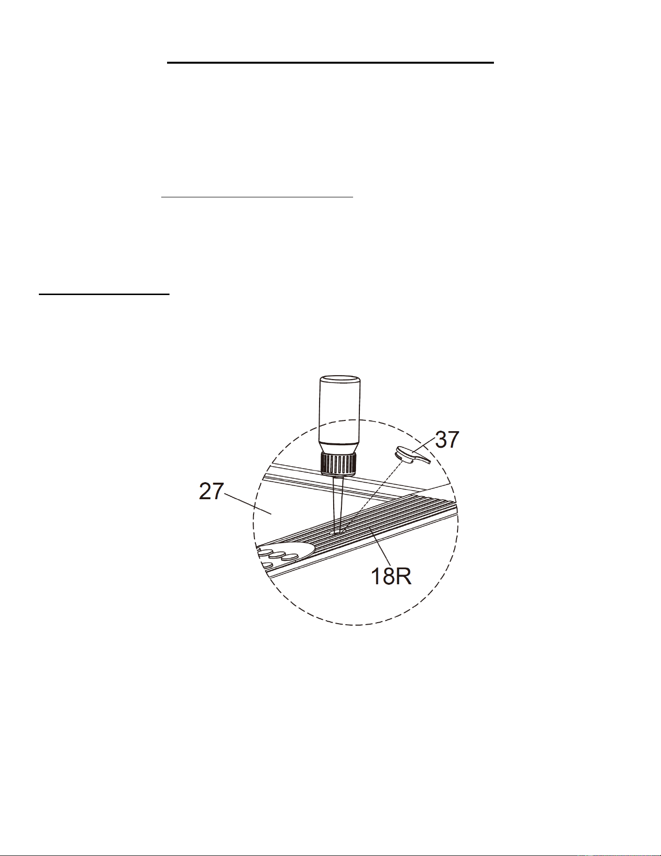
HOW TO LUBRICATE:
Open the Lubricant Plug (No. 37) on the Right Side Rail (No. 18R) and fill the lubricant into the
lubricant injection hole. Put the Lubricant Plug (No. 37) back in place after lubricant filling is finished.
Next, start the treadmill at the lowest speed setting and allow the lubricant to spread over the
Running Board (No. 27).
The following timetable is recommended:
Light user (less than 3 hours/ week) every five months
Medium user (4-7 hours/ week) every two months
Heavy user (more than 7 hours/ week) every month
9
MAINTENANCE & CARE
General cleaning will help prolong the life and performance of your treadmill. Keep the unit clean and
maintained by dusting the components on a regular basis. Clean both sides of the Running Belt (No.
28) to prevent dust from accumulating underneath the Running Belt (No. 28). Keep your running
shoes clean so that dirt from your shoes does not wear out the Running Board (No. 27) and
Running Belt (No. 28). Clean the surface of the Running Belt (No. 28) with a clean damp cloth.
To better maintain the treadmill and prolong its life it is suggested that the treadmill be powered off for
10 minutes every 2 hours of use and fully powered off whenever not in use.
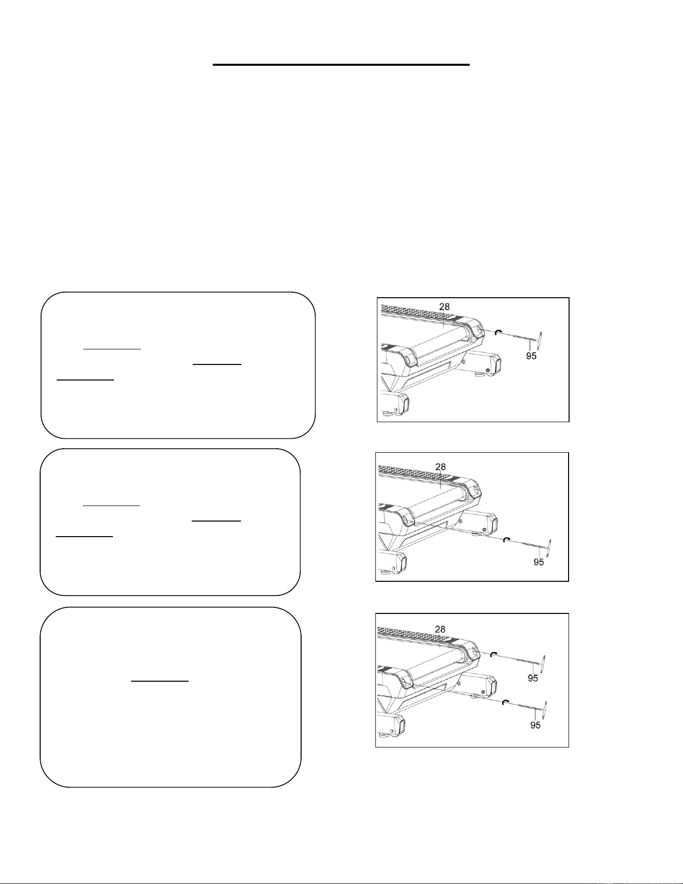
CENTERING THE RUNNING BELT:
Place the treadmill on level ground and set it at 3-5 MPH to check if the Running Belt (No. 28) drifts.
1. If the Running Belt (No. 28) moves to
the right, turn the right adjustment bolt ¼
turn clockwise, then turn the left
adjustment bolt ¼ turn counter-
clockwise. If the Running Belt (No. 28)
does not move, keep adjusting ¼ turn at
a time until it centers. Refer to Fig. 1.
2. If the Running Belt (No. 28) moves
to the left, turn left adjustment bolt ¼
turn clockwise, then turn the right
adjustment bolt ¼ turn counter-
clockwise. If the Running Belt (No.
28) does not move, keep adjusting ¼
turn at a time until it centers. Refer to
Fig. 2.
3. Over time the Running Belt (No.
28) will loosen. To tighten the belt,
turn the left and right adjustment bolts
one full turn clockwise, check the
tension of the Running Belt (No. 28).
Continue this process until Running
Belt (No. 28) is at the correct tension.
Make sure to adjust both sides
equally to ensure correct Running
Belt (No. 28) alignment. Refer to Fig.
3.
Fig. 1
Fig. 2
Fig. 3
10
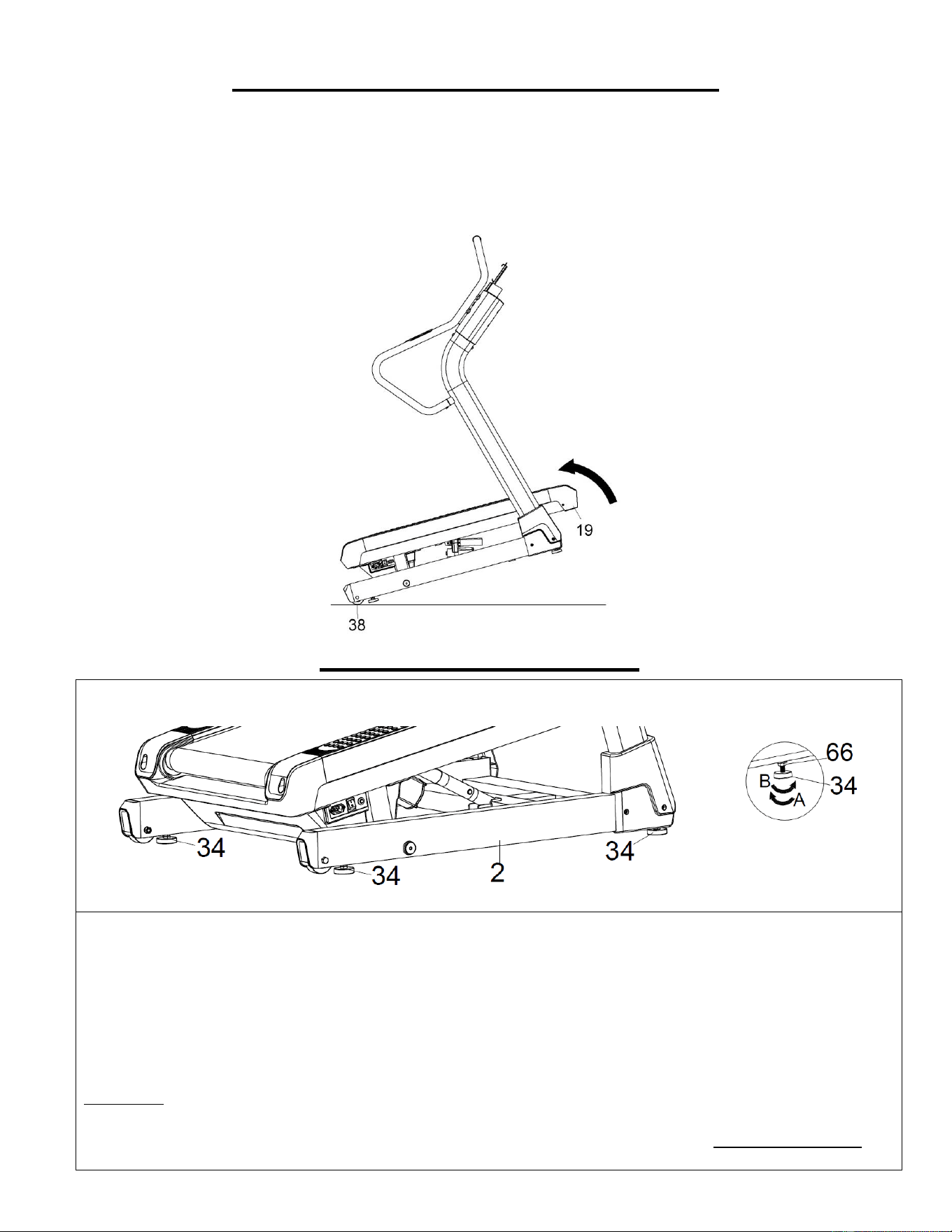
HOW TO MOVE THE TREADMILL
NOTE: It is suggested to have two people to help move the treadmill to avoid injury.
Hold the Front Protective Cover (No. 19) and tilt the treadmill until the Transportation Wheels (No.
38) touch the ground. With the Transportation Wheels (No. 38) on the ground, you can transport the
treadmill with ease.
ADJUSTMENT GUIDE
ADJUSTING THE BALANCE
To achieve a smooth and comfortable use, you must ensure that the treadmill is stable and
secure. If you notice that the treadmill is unbalanced during use, you should adjust the
Adjustable Pads (No. 34). There are a total of 4 Adjustable Pads (No. 34) located beneath the
Bottom Support (No. 2). Simply rotate the Adjustable Pads (No. 34) until the treadmill becomes
level with the floor surface.
To do so, loosen the Hex Thin Nut (No. 66) on the Adjustable Pad (No. 34) by turning it
clockwise (direction A). With the Hex Thin Nut (No. 66) loosened, rotate Adjustable Pad (No.
34) until it sits level with the surface that the treadmill is on. When you have finished adjusting the
Adjustable Pad (No. 34), re-tighten the Hex Thin Nut (No. 66) by turning it counter-clockwise
(direction B). If necessary, repeat this process to adjust the remaining Adjustable Pads (No. 34).
11
GROUNDING INSTRUCTIONS
WARNING: This treadmill requires a power source of 20 amps (120V) to properly operate. For
your safety, as well as the safety of others, please verify that the power source is correct before
powering the equipment. Any power source above or below this level could cause significant damage
to the equipment and/or user.
This product must be grounded. If it should malfunction or breakdown, grounding provides a path of
least resistance for electric current to reduce the risk of electric shock. This product is equipped with a
cord having an equipment-grounding conductor and a grounding plug. The plug must be plugged into
an appropriate outlet that is properly installed and grounded in accordance with all local codes and
ordinances.
DANGER – Improper connection of the equipment-grounding conductor can result in a risk of
electric shock. Check with a qualified electrician or serviceman if you are in doubt as to whether the
product is properly grounded. Do not modify the plug provided with the product – if it will not fit the
outlet, have a proper outlet installed by a qualified electrician.
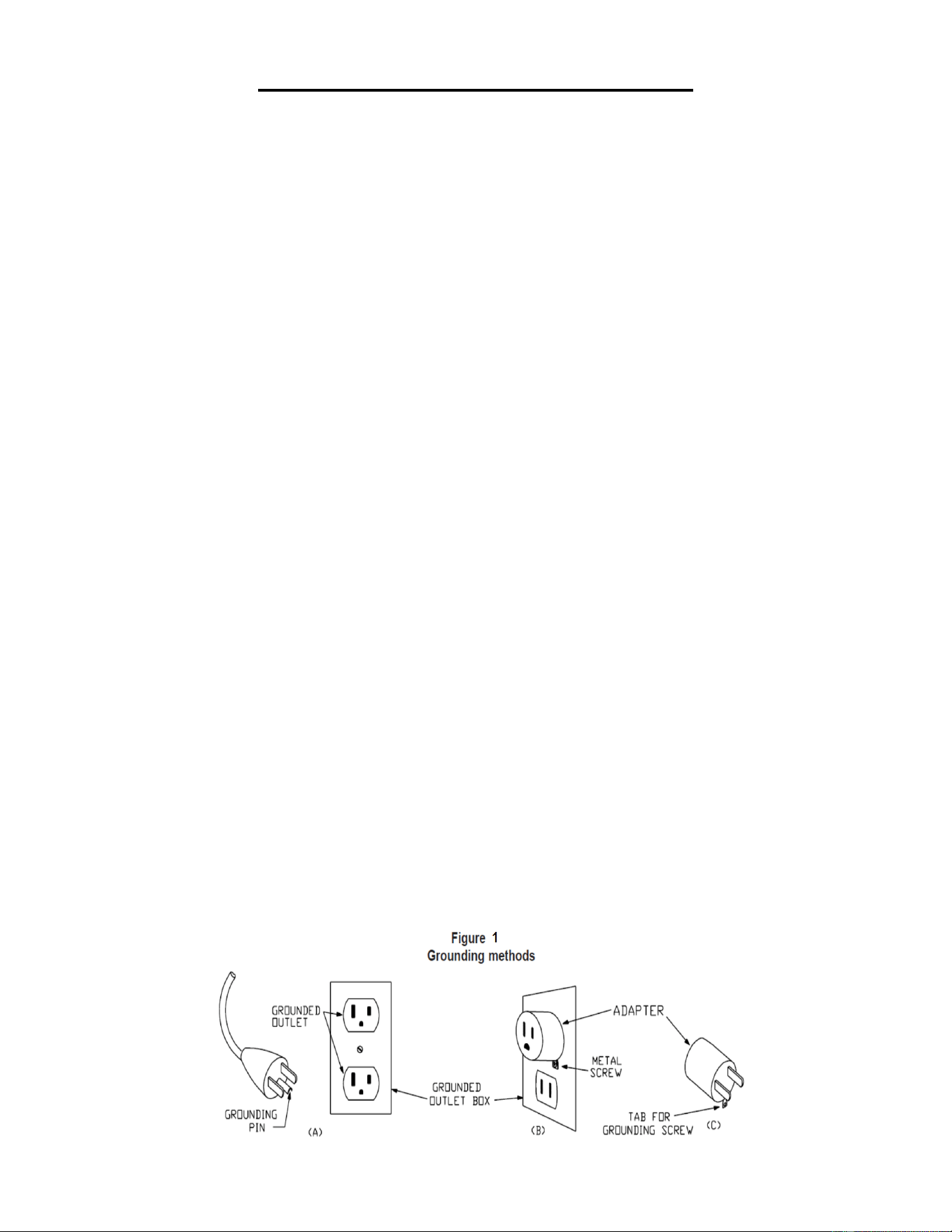
For a grounded, cord-connected product rated less than 15 A and intended for use on a nominal 120V
supply circuit, the instructions in either (1) or (2):
1) This product is for use on a nominal 120V circuit and has a grounding plug that looks like the plug
illustrated in sketch A in Figure 1. A temporary adapter that looks like the adapter illustrated in
sketches B and C may be used to connect this plug to a 2-pole receptacle as shown in sketch B if a
properly grounded outlet is not available.
The temporary adapter should be used only until a properly grounded outlet (sketch A) can be
installed by a qualified electrician. The green colored rigid ear, lug, or the like extending from the
adapter must be connected to a permanent ground such as a properly grounded outlet box cover.
Whenever the adapter is used, it must be held in place by a metal screw.
2) This product is for use on a nominal 120V circuit and has a grounding plug that looks like the plug
illustrated in sketch A in Figure 1. Make sure that the product is connected to an outlet having the
same configuration as the plug. No adapter should be used with this product.
WARNING!
1. NEVER use a ground fault circuit interrupt (GFCI) wall outlet with this treadmill. Route the power
cord away from any moving parts of the treadmill including the elevation mechanism and
transportation wheels.
2. NEVER operate the treadmill using a generator or UPS power supply.
2. NEVER remove any cover without first disconnecting the power cord.
3. NEVER expose the treadmill to rain or moisture. This treadmill is not designed for outdoor use or
use in any other high humidity environment.
12
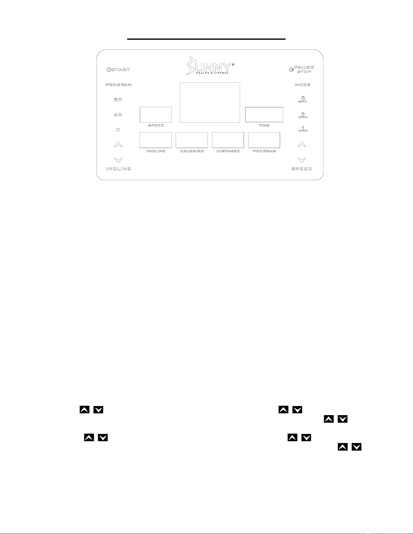
THE DISPLAY CONSOLE
WINDOW AND KEY DESCRIPTION
1. LED WINDOW FUNCTION
1) MAIN WINDOW: Standby or select the three countdown modes of TIME, DISTANCE and
CALORIES; displays the speed dot matrix diagram when selecting the program; displays error;
displays the runway and the number of laps, or the speed lift dot pattern.
2) SPEED WINDOW: Displays the current running speed. Data range: 0.0~5.0 MPH.
3) TIME WINDOW: Display the running time. Data range: 0:00~99:59.
4) INCLINE WINDOW: Display the incline. Data range: -5%~50%.
5) PROGRAM WINDOW: Displays the selected running program from “P01~P12”, “U01~U03”.
6) CALORIES WINDOW: Displays the calorie consumption value of the exercise. Data range:
0.0-999.
7) DISTANCE WINDOW: Displays the accumulated distance. Data range: 0.00~99.9.
2. KEY FUNCTION
1) PROGRAM KEY: In the standby state, press the “PROGRAM” key to select the program:
manual mode-P01-P02- -... -P12-U01-U02-U03.
2) MODE KEY: In the standby state, press the “MODE” key to select the mode: manual mode
(normal mode), time countdown mode, distance countdown mode, or calories countdown
mode.
3) START KEY: In the standby or pause state, press the “START” key to start the treadmill.
4) PAUSE/STOP KEY: When the treadmill is running, press the “PAUSE/STOP” key to pause the
treadmill. Time, distance, and calories data will be retained. The speed will go to zero. Press
the “PAUSE/STOP” key again to stop the treadmill and all data will be cleared to zero.
5) SPEED KEY: In the setting state, pressing the “SPEED ” keys will increase or
decrease the set value. When the treadmill is running, pressing the “SPEED ” keys will
increase or decrease the speed.
6) INCLINE KEY: In the setting state, pressing the “INCLINE ” keys will increase
or decrease the set value. When the treadmill is running, pressing the “INCLINE ” keys
will increase or decrease the incline.
7) SPEED SHORTCUT KEYS (1MPH, 3MPH, 5MPH): When the treadmill is running, pressing the
speed shortcut keys will adjust the treadmill speed directly to the speed value identified on the
key.
8) INCLINE SHORTCUT KEYS (0%, 25%, 50%): When the treadmill is running, pressing the
incline shortcut keys will adjust the incline to the incline value marked on the key.
13
9) In the standby state, press and hold the “SPEED ” keys for 3 seconds to view the total
distance. Press the "PAUSE/STOP" key for 3 seconds to clear the total distance. Then remove
the Safety Key (No. 76) and reinsert back into the safety key seat to return the treadmill back
to standby state.
10) In the standby state, press and hold the INCLINE ” keys for 3 seconds to enter the
incline self-test. After the incline self-test is finished, the treadmill will return to the standby
state.
PROGRAM INSTRUCTIONS
1. SCHEMATIC DESCRIPTION
1) Manual mode, which includes: normal mode, time countdown mode, calories countdown mode,
and distance countdown mode.
2) 12 fixed programs: P01, P02, …,P12.
3) 3 user programs: U01, U02, U03.
2. START INSTRUCTIONS
1) Attach the Safety Key (No. 76) to the safety key seat on the console support.
2) Press the “START” key, the main window will show: 3-2-1, and beep for each 3 countdowns,
then start the treadmill.
3. MANUAL MODE
1) How to get into the manual mode.
A. Turn on the power switch and go directly to the normal mode in the manual mode.
B. In the standby state, press the “MODE” key to select the normal mode in the manual mode.
2) Three setting functions in manual mode: time setting, distance setting, and calories setting.
A. In manual mode, the time window is 0:00.
B. In manual mode, press the “MODE” key to enter the time countdown mode. The time
window shows the time and flashes, and the initial time is: 30:00, then press the “SPEED
” keys, or “INCLINE ” keys to set the value. Time setting range: 5:00~99:00.
C. In the time countdown mode: press the “MODE” key to enter the distance countdown
mode. The distance window shows the initial distance 1.00 mile, then press the “SPEED
” keys, or “INCLINE ” keys to set the value. Distance setting range: 0.50~99.9
miles, and each increase or decrease is 0.1 mile.
D. In the distance countdown mode, press the “MODE” key to enter the calories countdown
mode. The calories window shows the initial calories 50.0 kcal, then press the “SPEED
” keys, or “INCLINE ” keys to set the value. Calories setting range: 10.0~999 kcal,
and each increase or decrease is 1 kcal.
3) Operation in the manual mode
A. Press the “START” key for 3 seconds, the treadmill will start running with an initial speed of
0.3 MPH.
B. Press the “SPEED ” keys to adjust the speed.
C. Press the “INCLINE ” keys to adjust the incline.
D. Press the speed shortcut keys to quickly set the speed identified by the key.
E. Press the incline shortcut keys to quickly set the incline identified by the key.
F. When the treadmill is running, press the "PAUSE/STOP" key and the treadmill will stop
running.
G. When the set time, calories, or distance decreases to zero, the console will beep 1 short
time. The speed will slowly decrease until it comes to a complete stop, then the console will
beep 3 long times, and the main window display “End”. After 5 seconds, the console will go
back to the standby state, beep 2 long times, and the main window will display “Welcome”.
H. Parameters with no value set will count upward. The value will return to zero after reaching
maximum display range for calories and distance. The treadmill will stop if the time
exceeds 99:59 (100 minutes) in manual mode.
14
4. FIXED PROGRAM
1) In the standby state, press “PROGRAM” key and the program window will show “P01, P02,
-…P12”. After choosing the program, the time window will show the initial time: 30 minutes.
Pressing the “SPEED ” keys, or “INCLINE ” keys to set the time, and only time
can be adjusted. The time setting range is from 5:00 to 99:00.
2) Press the “START” key, the treadmill will start running, and the speed will gradually increase to
the speed indicated in the first section of the program (see the program value table for details).
3) Press the “SPEED ” keys to adjust the speed.
4) Press the “INCLINE ” keys to adjust the incline.
5) Press the speed shortcut keys to quickly set the speed represented by the key.
6) Press the incline shortcut keys to quickly set the incline represented by the key.
7) Each program is divided into 20 segments, and operation time for each segment is 1/20 of the
set time.
8) When switching from one segment to another, the console will beep three times.
9) When the setting time decreases to zero, the console will beep 1 short time. The speed will
slowly decrease until it comes to a complete stop, then the console will beep 3 long times, and
the main window displays “End”. After 5 seconds, the console will go back to the standby
state, beep 2 long times, and the main window will display “Welcome”.
Program Table
Setup time / 20 = each segment of the running time
1
2
3
4
5
6
7
8
9
10
11
12
13
14
15
16
17
18
19
20
P01
SPEED
1.2
1.2
1.2
1.2
1.8
1.8
1.8
1.8
2.4
2.4
2.4
2.4
3
3
3
3
3
1.8
1.8
0.6
INCLINE
0
1
1
1
1
1
2
2
2
2
3
3
3
2
2
3
2
2
2
2
P02
SPEED
1.2
1.8
1.8
1.8
1.8
2.4
2.4
3
3
3
2.4
2.4
3
3
3
2.4
2.4
3
1.8
1.2
INCLINE
0
1
2
3
4
5
4
5
4
2
1
2
3
2
1
1
2
3
3
2
P03
SPEED
1.2
1.2
1.2
1.8
1.8
1.8
2.4
2.4
2.4
2.4
3
3
3.6
3.6
3.6
3
3
3
2.4
1.8
INCLINE
0
2
2
4
4
4
6
6
6
7
7
8
8
8
8
6
6
6
4
3
P04
SPEED
1.2
1.8
1.8
2.4
3
3.6
3.6
3.6
3
3
3
3.6
3.6
3.6
3.6
3
3
3
2.4
2.4
INCLINE
1
1
2
2
4
4
5
5
5
6
6
6
8
8
10
10
8
6
6
3
P05
SPEED
1.2
3
3
3
3.6
3.6
3.6
4.8
4.2
4.2
3.6
3
2.4
1.8
1.8
1.8
3
3
2.4
2.4
INCLINE
0
2
8
8
8
9
9
10
10
12
12
12
14
14
14
13
13
12
10
6
P06
SPEED
1.2
3.6
3.6
3.6
4.2
4.2
4.2
4.2
3.6
3.6
4.8
4.8
4.2
4.2
3.6
3.6
3
3
3.6
2.4
INCLINE
0
8
10
14
16
18
20
22
24
25
25
22
20
18
17
16
15
15
12
3
P07
SPEED
1.2
1.8
1.8
3
1.8
1.8
4.2
4.2
3.6
3.6
3
3
2.4
4.8
4.8
4.8
3.6
3.6
3
1.8
INCLINE
0
8
12
13
13
13
15
15
15
16
16
18
18
20
20
22
22
23
20
5
P08
SPEED
1.2
2.4
3.6
3.6
3.6
3
4.8
4.8
3.6
4.2
4.2
3
3
3
3
4.8
4.2
4.2
3.6
3.6
INCLINE
2
2
6
6
8
7
9
12
12
14
16
20
22
22
18
18
18
15
15
5
P09
SPEED
0.6
1.2
1.2
1.8
1.8
1.2
1.2
1.8
1.8
1.2
1.2
1.8
1.8
2.4
2.4
1.8
1.8
1.8
1.2
0.6
INCLINE
24
25
26
28
29
25
26
28
29
25
26
28
29
25
26
25
26
25
25
0
P10
SPEED
0.6
1.2
1.8
1.8
1.8
2.4
2.4
3
3
2.4
2.4
1.8
1.8
1.8
1.2
1.8
1.8
1.2
1.2
0.6
INCLINE
24
28
25
25
28
25
28
25
28
28
25
25
28
27
24
28
30
32
34
0
P11
SPEED
0.6
1.2
1.8
2.4
3
1.8
2.4
3
1.8
2.4
3
2.4
1.8
2.4
2.4
1.8
1.8
1.2
1.2
0.6
INCLINE
20
22
24
26
28
30
26
28
24
26
28
30
30
32
34
36
34
34
32
0
P12
SPEED
0.6
1.2
1.2
1.8
1.8
2.4
2.4
1.8
1.8
1.2
1.8
1.2
1.8
1.8
1.8
1.2
1.2
1.8
1.2
0.6
INCLINE
20
22
24
24
26
26
28
28
30
30
28
26
24
22
20
22
24
26
25
0

15
5. USER PROGRAM
The treadmill has three user programs that allow users to set up according to their personal
preferences: U01, U02, U03.
1) User program settings:
In standby state, continuously press the “PROGRAM” key until the user program (U01-U03) is
selected. Press the "MODE" key to confirm the setting, and then adjust the first time-period.
When setting speed, use the “SPEED ” keys or speed shortcut keys, and use the
“INCLINE ” keys to set the incline. Press the "MODE" key to complete the setting for the
first time-period and enter the setting state for the second time-period until all 20 time-periods
are set. After the setting is completed, the data will be saved until you reset it, this data will not
be lost due to power outage.
2) Start the user program:
A. Press the “PROGRAM” key continuously in standby state until the user program (U01-U03)
is selected. Set the running time before pressing the “START” key to start the program.
B. After the user program and run time is set, press the “START” key to start immediately.
3) User program settings description:
Each program divides the movement time into 20 time-periods. Speed, incline, and running
time settings for all 20 time-periods must be set before pressing the “START” key to start the
treadmill.
DISPLAY RANGE OF VARIOUS PARAMETERS
PARAMETER
INITIAL VALUE
SET INITIAL VALUE
SETTING RANGE
DISPLAY RANGE
TIME (minute: second)
0:00
30:00
5:00-99:00
0:00-99:59
SPEED (MP/H)
0.0
-
0.3-5.0
0.0-5.0
INCLINE (%)
0.00
0.00
-5-50
-5-50
DISTANCE (MILE)
0.00
1.00
0.50-99.9
0.00-99.9
CALORIES (KCAL)
0.0
50.0
10.0-999
0.0-999
SAFETY KEY FUNCTION
Removing the Safety Key (No. 76) in any mode will rapidly decrease the speed of the treadmill until it
stops. All keys will be invalid. The console will beep 3 times and “----/---” will be displayed on the main
window. The main window moving display “SAFETY KEY DISCONNECTED”. Insert the Safety Key
(No. 76) back into the console to re-enter into standby state and ready for you to input commands.
POWER SAVING MODE
This console has power saving function. In the standby state, if there is no commands input for 10
minutes, the console will enter power saving mode, shutting down the display automatically. The
console can be awakened by pressing any key.
SHUTDOWN
You can turn off the treadmill at any time by turning off the power switch, which does not damage the
treadmill.
MATTERS THAT NEED ATTENTION
1. Check the power supply before exercising; check whether the Safety Key (No. 76) is working.
2. If any abnormal situation occurs during exercise, remove the Safety Key (No. 76) and the
treadmill will quickly come to a stop. Put the Safety Key (No. 76) back into the console to reset
the equipment and wait for input instructions.

16
3. If there is any problem with this machine, please contact us ([email protected]).
Non-professional personnel should not try to remove or repair the machine, to avoid damage to
the equipment.
TROUBLESHOOTING
Error
Possible reasons
Solutions
E01
Controller can not receive signal
from inverter.
1.Check the cable between the controller and inverter.
2.Replace the cable between the controller and inverter.
3.Replace the controller.
4.Replace the inverter.
E03
Overvoltage.
Stop use, check external cable.
E04
Overcurrent.
1.Replace the motor.
2.Check transmission parts, add lubricant.
3.Replace the inverter.
E05
Overload.
1.Check transmission parts, add lubricant.
2.Replace the motor.
E06
Inverter MCU breakdown.
Replace the inverter.
E07
Inverter overheated.
1.Stop use and use it after the temperature has returned
to normal.
2.Replace the inverter.
E08
Inverter can not receive signal from
controller.
1.Check the cable between the controller and inverter.
2.Replace the cable between the controller and inverter.
3.Replace the controller.
4.Replace the inverter.
E09
Inverter inside communication error
1.
Replace the inverter.
E10
Inverter inside communication error
2.
Replace the inverter.
E11
Received boot signal, but before
the shutdown signal has not been
received.
Replace the inverter.
E12
Lifting fault.
1.Check the cable of lifting motor.
2.Replace the lifting motor.
3.Replace the inverter.
E13
Reverse switch action.
Put the treadmill horizontally.
E14
Stator phase fault.
Stop use, check external cable.
E15
Current sensor U fault.
Replace the inverter.
E16
Current sensor W fault.
Replace the inverter.
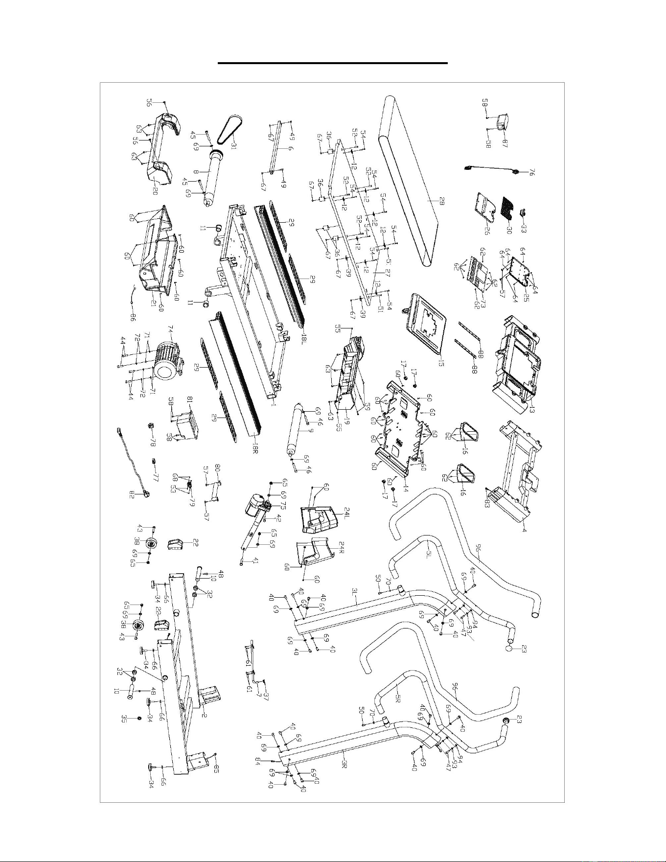
17
EXPLODED DIAGRAM

18
PARTS LIST
No.
Description
Spec.
Qty.
No.
Description
Spec.
Qty.
1
Main Frame
1
31
Belt
250J
1
2
Bottom Support
1
32
Spacer
Φ32XΦ25X14
4
3L
Left Upright Tube
1
33
Tablet Holder Clip
70.6X37.4X26.
3
1
3R
Right Upright Tube
1
34
Adjustable Pad
Φ53XM10X13
4
4
Console Support
1
35
Grommet
Φ12XΦ24X9
1
5L
Left Handrail
1
36
Cushion
Φ30X32
4
5R
Right Handrail
1
37
Lubricant Plug
34.5X20X8
1
6
Strengthen Tube
1
38
Transportation Wheel
Φ75X26
2
7
Lubricant Tube
Connection
1
39
Plastic Cushion
35XΦ10X2.0
2
8
Front Roller
Φ20X680XΦ90X
Φ63X580
1
40
Inner Hex Bolt
M10X20
16
9
Rear Roller
Φ20X649XΦ56X5
65
1
41
Hex Bolt
M10X65
1
10
Axle
Φ20X649XΦ56X5
65
2
42
Hex Bolt
M10X45
1
11
Spacer
Φ38XΦ25X39
2
43
Hex Bolt
M10X60
2
12
Pressing Plate
25X20X2.0
8
44
Socket Head Cap Bolt
M10X30
4
13
Console Upper
Cover
906X360X84
1
45
Socket Head Cap Bolt
M10X70
2
14
Console Bottom
Cover
906X343.7X94.5
1
46
Socket Head Cap Bolt
M10X65
2
15
Console Board
473.4X356X82
1
47
Socket Head Cap Bolt
M8X35
4
16
Bottle Holder
2
48
Socket Head Cap Bolt
M8X20
2
17
Front Handlebar End
Cap
Φ23.6X15.2
4
49
Socket Head Cap Bolt
M6X15
2
18L
Left Side Rail
104X77.6X1029
1
50
Inner Hex Flat Head Bolt
M8X15
2
18R
Right E Side Rail
104X77.6X1029
1
51
Inner Hex Sunk Bolt
M6X30
2
19
Front Protective
Cover
718X143.5X158
1
52
Inner Hex Sunk Bolt
M6X25
4
20
Rear Protective
Cover
718X154.6X142
1
53
Cross Sunk Head Screw
M3X15
2
21
Motor Cover
695X377.5X164
1
54
Cross Pan Head Bolt
M5X30
8
22
Roller Cover
100X60X50
2
55
Phillips Sunk Tapping
Screw
ST4.0X16
2
23
End Cap
Φ44X32
2
56
Phillips Screw
M5X16
2
24L
Left Upright Tube
Cover
203.5X64.7X254
1
57
Phillips Screw
M5X8
4
24R
Right Upright Tube
Cover
203.5X64.7X254
1
58
Phillips Screw
M4X8
6
25
Tablet Holder Bottom
Cover
220X170X27.6
1
59
Phillips Tapping Screw
ST4X35
3
26
Tablet Holder Upper
Cover
220X170X8.6
1
60
Phillips Tapping Screw
ST4X16
38
27
Running Board
1020X693Xt18
1
61
Phillips Tapping Screw
ST4.0X12
4
28
Running Belt
510X2405Xt2.5
1
62
Phillips Tapping Screw
ST2.9X8
16
29
Rubber Cushion
428.2X90X3.3
4
63
Phillips Tapping Screw
ST4.0X16
8
30
Rubber Pad
212.8X99.3X1.4
1
64
Phillips Tapping Screw
ST2.9X6
8

19
Version 1.0
No.
Description
Spec.
Qty.
No.
Description
Spec.
Qty.
65
Nylon Nut
M10
4
81
Inverter
1
66
Hex Thin Nut
M10
4
82
Power Cord
2000MM
1
67
Hex Nut
M6
8
83
Console Upper Cable
950MM
1
68
Hex Nut
M3
2
84
Console Middle Cable
1450MM
1
69
Serrated Lock
Washer
Φ10X1.2
24
85
Console Lower Cable
1700MM
1
70
Serrated Lock
Washer
Φ8X1.2
2
86
Controller Cable
550MM
1
71
Flat Washer
Φ10X2.0
4
87
Filter
1
72
Spring Washer
Φ10
4
88
Keyboard
2
73
Console
1
89
Allen Wrench
S5
1
74
Ac Motor
2.5HP
1
90
Allen Wrench
S6, L170X70
1
75
Incline Motor
1/8HP
1
91
Allen Wrench
S6
1
76
Safety Key
1
92
Spanner
S13, S14,
S15, S17
1
77
Circuit Breaker
AC 250V
1
93
Spring Washer
Φ8
4
78
Switch
250V/15A
1
94
Flat Washer
Φ8
4
79
Power Socket
15A
1
95
T-shaped Wrench
S6, S8, S8,
L150
1
80
Rheostat
1
96
Foam Grip
Φ36XT3X172
0
2