Please give us a chance to make it right and do better !
Contact our friendly customer service department for help first.
Replacements for missing or damaged parts will be shipped ASAP !
Contact Us!
Do NOT return this item.
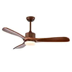
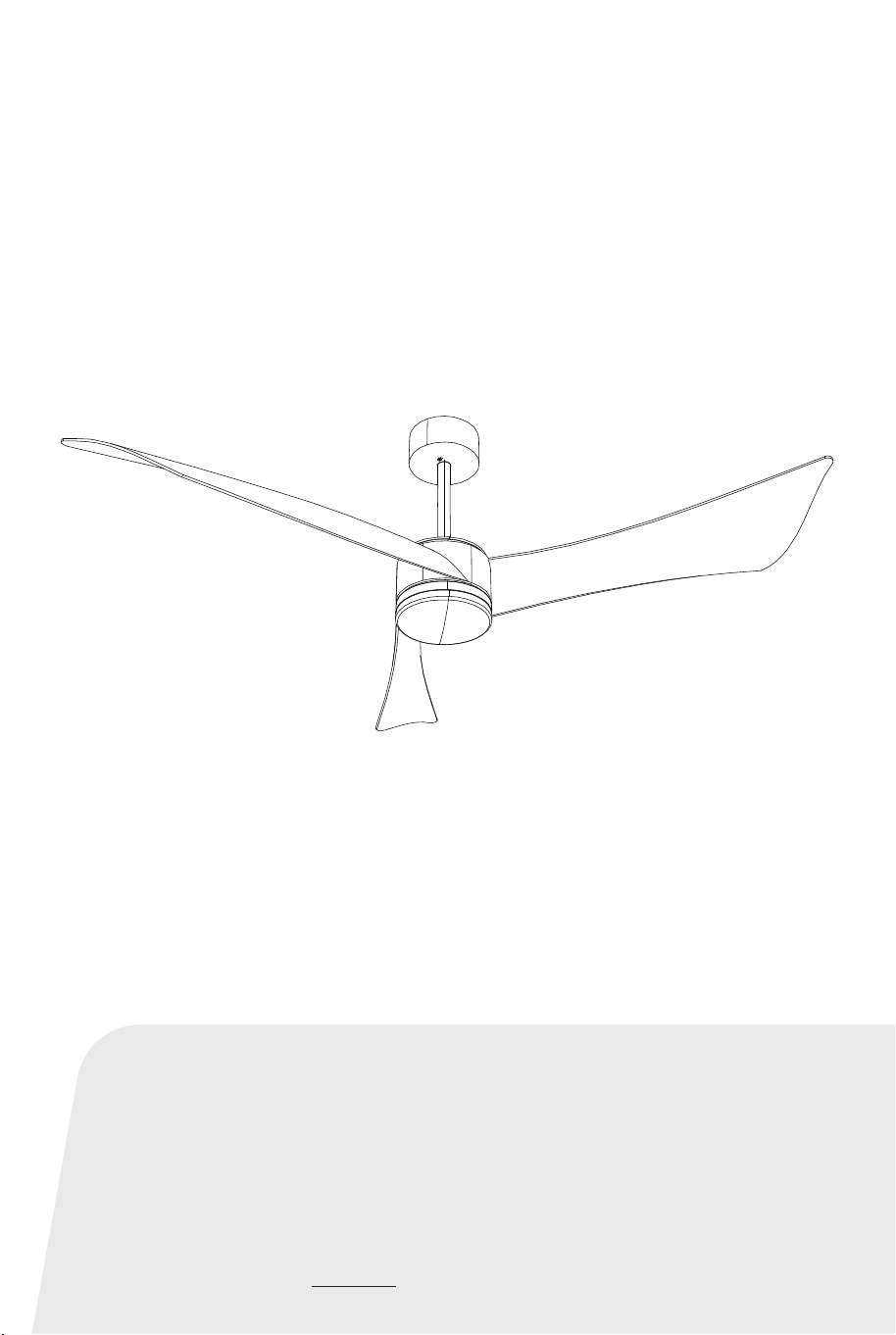
CEILING FAN
ES10186US
USER’S MANUAL
THIS INSTRUCTION BOOKLET CONTAINS IMPORTANT SAFETY INFORMATION. PLEASE READ AND KEEP FOR FUTURE REFERENCE.
US office: Fontana UK office: Ipswich AU office: Truganina
DE office: Hamburg
FR office: Saint Vigor d'Ymonville
PL office: Gdańsk
US:cs.us@costway.com
UK:cs.uk@costway.com
Before You Start
Please read all instructions carefully.
Retain instructions for future reference.
Separate and count all parts and hardware.
Read through each step carefully and follow the proper order.
We recommend that, where possible, all items are assembled
near to the area in which they will be placed in use, to avoid
moving the product unnecessarily once assembled.
Always place the product on a flat, steady and stable surface.
Keep all small parts and packaging materials for this product
away from babies and children as they potentially pose a serious
choking hazard.
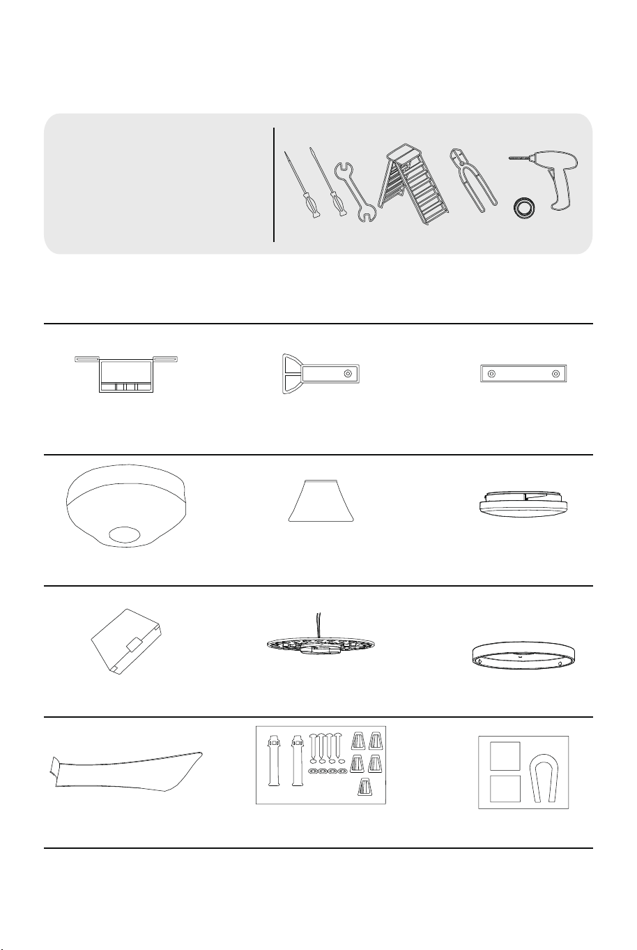
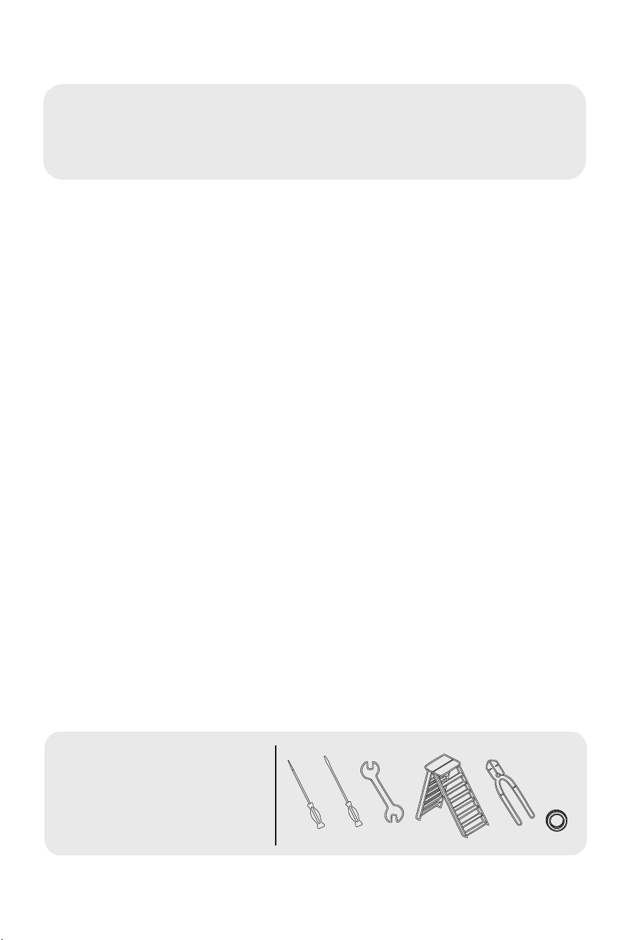
1) Tools Ready
2) Parts Inspection
• Philips screwdriver
• Blade screwdriver
• Adjustable pliers or wrench
• Step ladder
• Wire cutter
• Electrical tape
• Lmpact drill
Hanger bracket 5-inch down rod 10-inch downrod
1 x1 2 x1 3 x1
4 x1 5 x1 6 x1
7 x1 8 x1 10 x1
11 x3 12 x5
13 x2
Canopy Decorative cover Translucent lampshade
Remote controller Lighting
Light chassis
Fan blade Expansion screws
Balance package
02 03
Before You Start
Please read all instructions carefully.
Retain instructions for future reference.
Separate and count all parts and hardware.
Read through each step carefully and follow the proper order.
We recommend that, where possible, all items are assembled
near to the area in which they will be placed in use, to avoid
moving the product unnecessarily once assembled.
Always place the product on a flat, steady and stable surface.
Keep all small parts and packaging materials for this product
away from babies and children as they potentially pose a serious
choking hazard.
1) Tools Ready
2) Parts Inspection
• Philips screwdriver
• Blade screwdriver
• Adjustable pliers or wrench
• Step ladder
• Wire cutter
• Electrical tape
• Lmpact drill
Hanger bracket 5-inch down rod 10-inch downrod
1 x1 2 x1 3 x1
4 x1 5 x1 6 x1
7 x1 8 x1 10 x1
11 x3 12 x5
13 x2
Canopy Decorative cover Translucent lampshade
Remote controller Lighting
Light chassis
Fan blade Expansion screws
Balance package
02 03
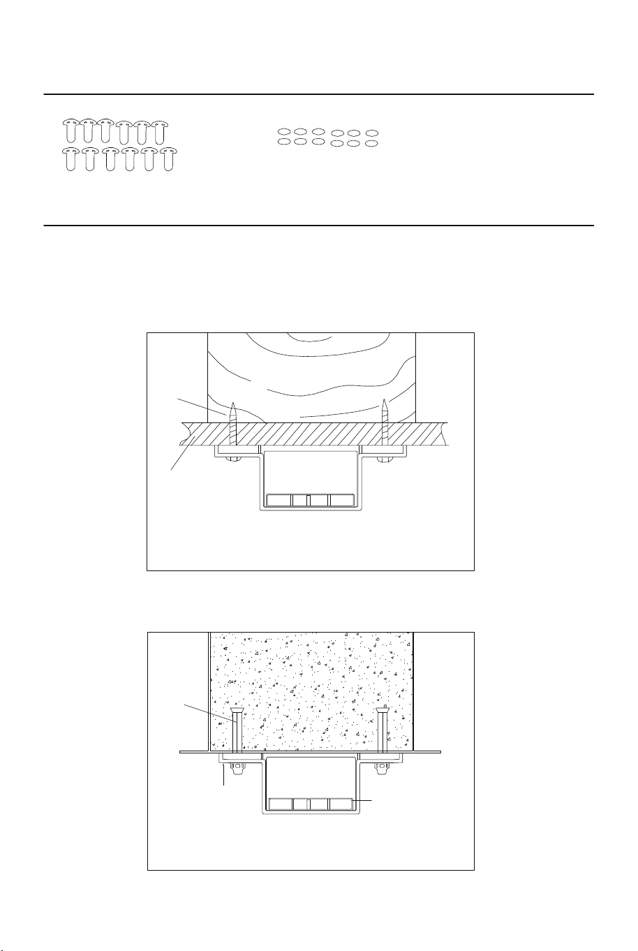
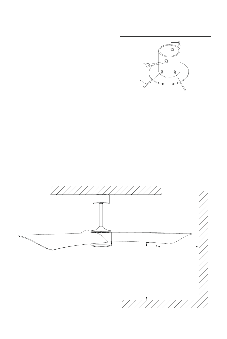
3) Installation of Bracket
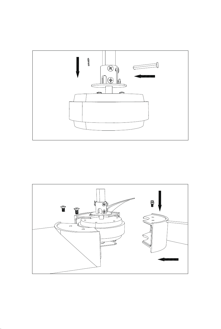
4) Install the Blades
Use wood screws to fix bracket for wooden or false ceiling.
Use expansion screws to fix bracket for concrete ceiling before that
will need to drill dia.8mm expansion bolts.
1.
Install the boom safety pin boom and the hanger.(Figure 1)
1.
2.
Install the fan blades to the motor in order and screw on the fan blade
screws in turn.(Figure 2)
2.
14 x12
Figure 1
Figure 2
Expansion
screw
Fixed
seat
Lift the
ball
15 x12
Blade screw Shim
Wood
screws
Beam
04 05
3) Installation of Bracket
4) Install the Blades
Use wood screws to fix bracket for wooden or false ceiling.
Use expansion screws to fix bracket for concrete ceiling before that
will need to drill dia.8mm expansion bolts.
1.
Install the boom safety pin boom and the hanger.(Figure 1)
1.
2.
Install the fan blades to the motor in order and screw on the fan blade
screws in turn.(Figure 2)
2.
14 x12
Figure 1
Figure 2
Expansion
screw
Fixed
seat
Lift the
ball
15 x12
Blade screw Shim
Wood
screws
Beam
04 05
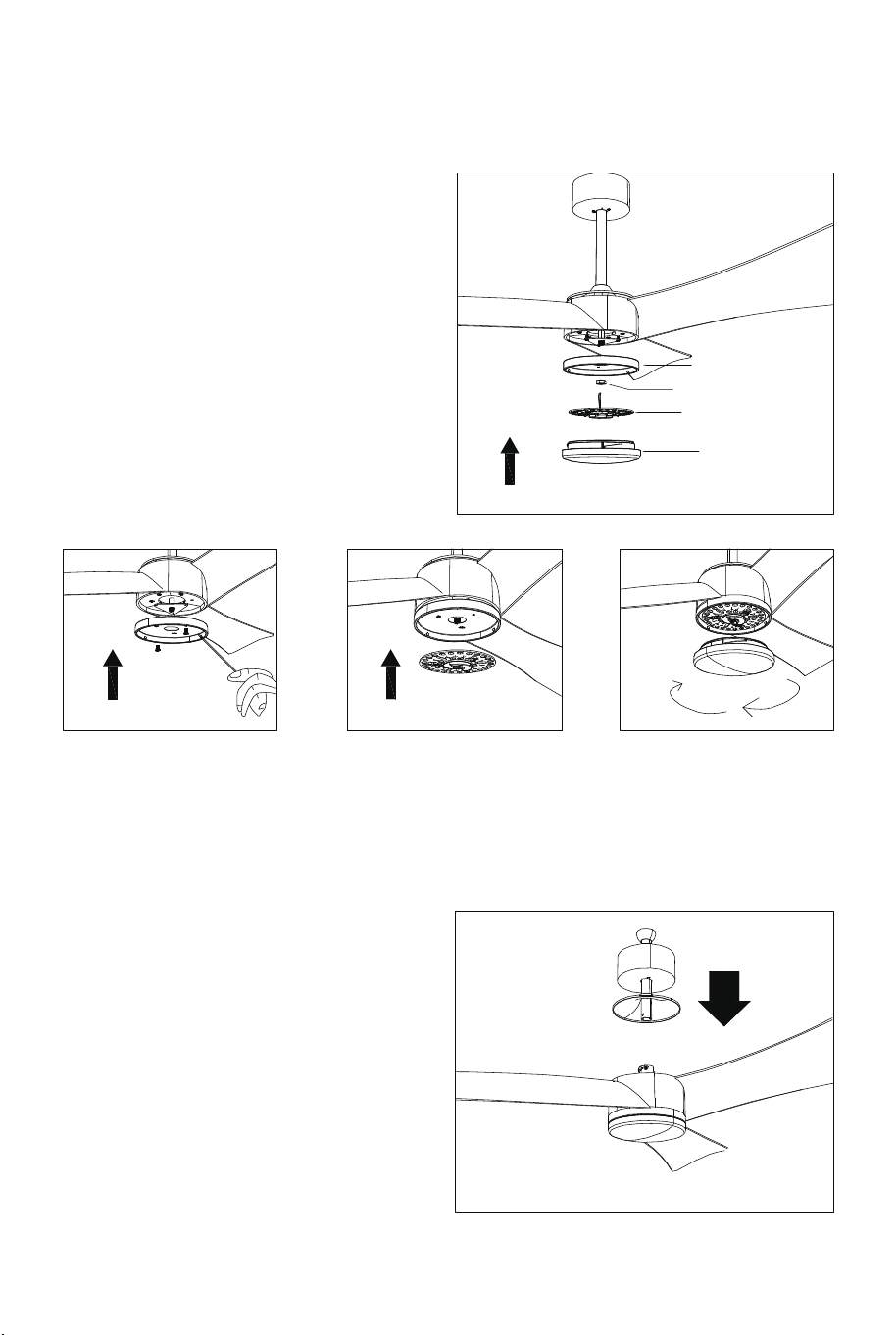
5) Lamp Installation
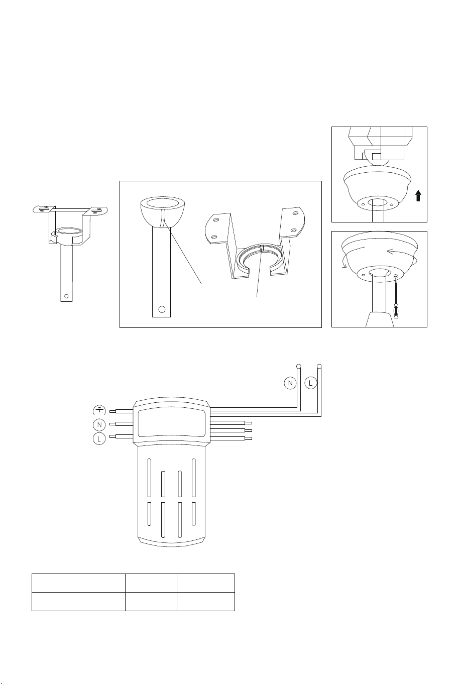
6) Installation of downrod, canopy and
decorative cover selection of downrod
7) Installation Height
1. Connect the corresponding wires
at the bottom of the lamp and the
motor.
2. Tighten the three screws on the
edge of the switch cover.
3. Take out the decorative nuts,
nuts, iron washers and plastic
washers pre—locked on the lamp
tube.
4. lnstall glass, tighten plastic
washer, iron washer and nut in turn.
5. lnstall the decorative frame and
fasten the decorative nut.
1. To select the correct downrod,
either 5-inch or 10-inch according to
the ceiling height. Put the canopy
and decorative cover through the
downrod;
2. Remove the locking pin and the
long pin, then remove the two
downrod set screws;
3. Fix the downrod set into the fan
body, lock the downrod to the fan
body with set screws.
4. Mount the bracket onto outlet box
by the screws, spring washers and flat
washers.
5. Hang the ball joint and the fan onto
the bracket, make sure the guide pin
of the bracket is fitted into slot of ball
joint.
6. Insert the remote control receiver
between the bracket and the downrod.
7. Connect wires from supply and the
bracket to the wiring terminals.
8. Attach the canopy to the bracket by
the aligning canopy holes with the
bracket holes. Fix the canopy to
bracket with set screws.
9. Install the blade brackets and
blades with screws.
Figure 1 Figure 2
Figure 3
Light source
chassis
Fan blades to the ground shall
not less than 7.5ft.
Light source
Locking
pin
Pin
Downrod
setscrew
Downrod
setscrew
Lampshade
Hex nuts
1.6ft
7.5ft
06 07
5) Lamp Installation
6) Installation of downrod, canopy and
decorative cover selection of downrod
7) Installation Height
1. Connect the corresponding wires
at the bottom of the lamp and the
motor.
2. Tighten the three screws on the
edge of the switch cover.
3. Take out the decorative nuts,
nuts, iron washers and plastic
washers pre—locked on the lamp
tube.
4. lnstall glass, tighten plastic
washer, iron washer and nut in turn.
5. lnstall the decorative frame and
fasten the decorative nut.
1. To select the correct downrod,
either 5-inch or 10-inch according to
the ceiling height. Put the canopy
and decorative cover through the
downrod;
2. Remove the locking pin and the
long pin, then remove the two
downrod set screws;
3. Fix the downrod set into the fan
body, lock the downrod to the fan
body with set screws.
4. Mount the bracket onto outlet box
by the screws, spring washers and flat
washers.
5. Hang the ball joint and the fan onto
the bracket, make sure the guide pin
of the bracket is fitted into slot of ball
joint.
6. Insert the remote control receiver
between the bracket and the downrod.
7. Connect wires from supply and the
bracket to the wiring terminals.
8. Attach the canopy to the bracket by
the aligning canopy holes with the
bracket holes. Fix the canopy to
bracket with set screws.
9. Install the blade brackets and
blades with screws.
Figure 1 Figure 2
Figure 3
Light source
chassis
Fan blades to the ground shall
not less than 7.5ft.
Light source
Locking
pin
Pin
Downrod
setscrew
Downrod
setscrew
Lampshade
Hex nuts
1.6ft
7.5ft
06 07
8) Hanging Ceiling Fan
Place the lobes in the hanger and turn the pipe so the groove on the lobes
engages the lugs on the dome (inside the hanger).
RF wireless digital transmission technology, one—to—one control, the
weight rate is less than one part of a million (if there is any damage,
please contact the after-sales service.)
In the allowable space, the load can be controlled by any angle of the
remote control and the direction is not limited.
1. The remote control and receiver are paired as learning
codes. The remote control is turned to receive the controller
within one minute after the receiver is powered on; Long press
the natural wind button about 5 seconds, in the sound of a
drop, that learning success, can be used normally: (note: no
learning is accepted if the power is energized for more than
one minute).
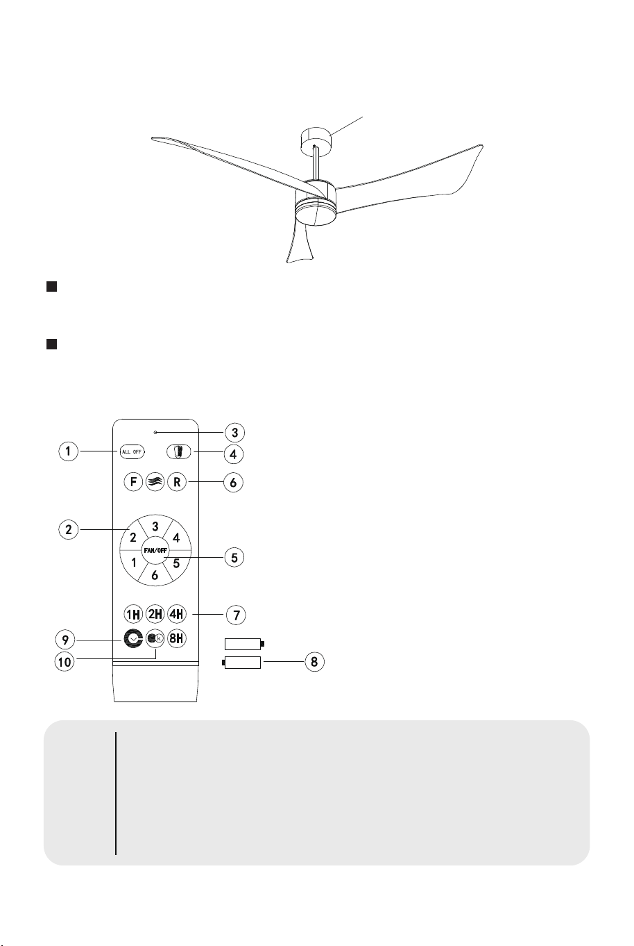
1. Turn off all loads
2. Fan speed control
3. LED indicator light
4. Turn on the light
5. Fan off
6. Fan positive and negative rotation
control
7. Fan timing control
8. The remote control uses a pair of
1.5v batteries
9. Automatically turn off fan and light
after 1 minute
10. Light color
The lug groove must engage the hanger lug.
Schematic diagram of controller wiring
Schematic diagram of controller installation
Instructions for remote control
Tips:
earth wire
white line
Red Line
grey line
pink thread
white line (input
zero line)
Input: 120V
The controller
Blue line
(input
fire line)
black thread
Power meter
Power supply Fan Lamp
120V 35W 18W
Lobed coneave groove
hanger lugs
08 09
8) Hanging Ceiling Fan
Place the lobes in the hanger and turn the pipe so the groove on the lobes
engages the lugs on the dome (inside the hanger).
RF wireless digital transmission technology, one—to—one control, the
weight rate is less than one part of a million (if there is any damage,
please contact the after-sales service.)
In the allowable space, the load can be controlled by any angle of the
remote control and the direction is not limited.
1. The remote control and receiver are paired as learning
codes. The remote control is turned to receive the controller
within one minute after the receiver is powered on; Long press
the natural wind button about 5 seconds, in the sound of a
drop, that learning success, can be used normally: (note: no
learning is accepted if the power is energized for more than
one minute).
1. Turn off all loads
2. Fan speed control
3. LED indicator light
4. Turn on the light
5. Fan off
6. Fan positive and negative rotation
control
7. Fan timing control
8. The remote control uses a pair of
1.5v batteries
9. Automatically turn off fan and light
after 1 minute
10. Light color
The lug groove must engage the hanger lug.
Schematic diagram of controller wiring
Schematic diagram of controller installation
Instructions for remote control
Tips:
earth wire
white line
Red Line
grey line
pink thread
white line (input
zero line)
Input: 120V
The controller
Blue line
(input
fire line)
black thread
Power meter
Power supply Fan Lamp
120V 35W 18W
Lobed coneave groove
hanger lugs
08 09
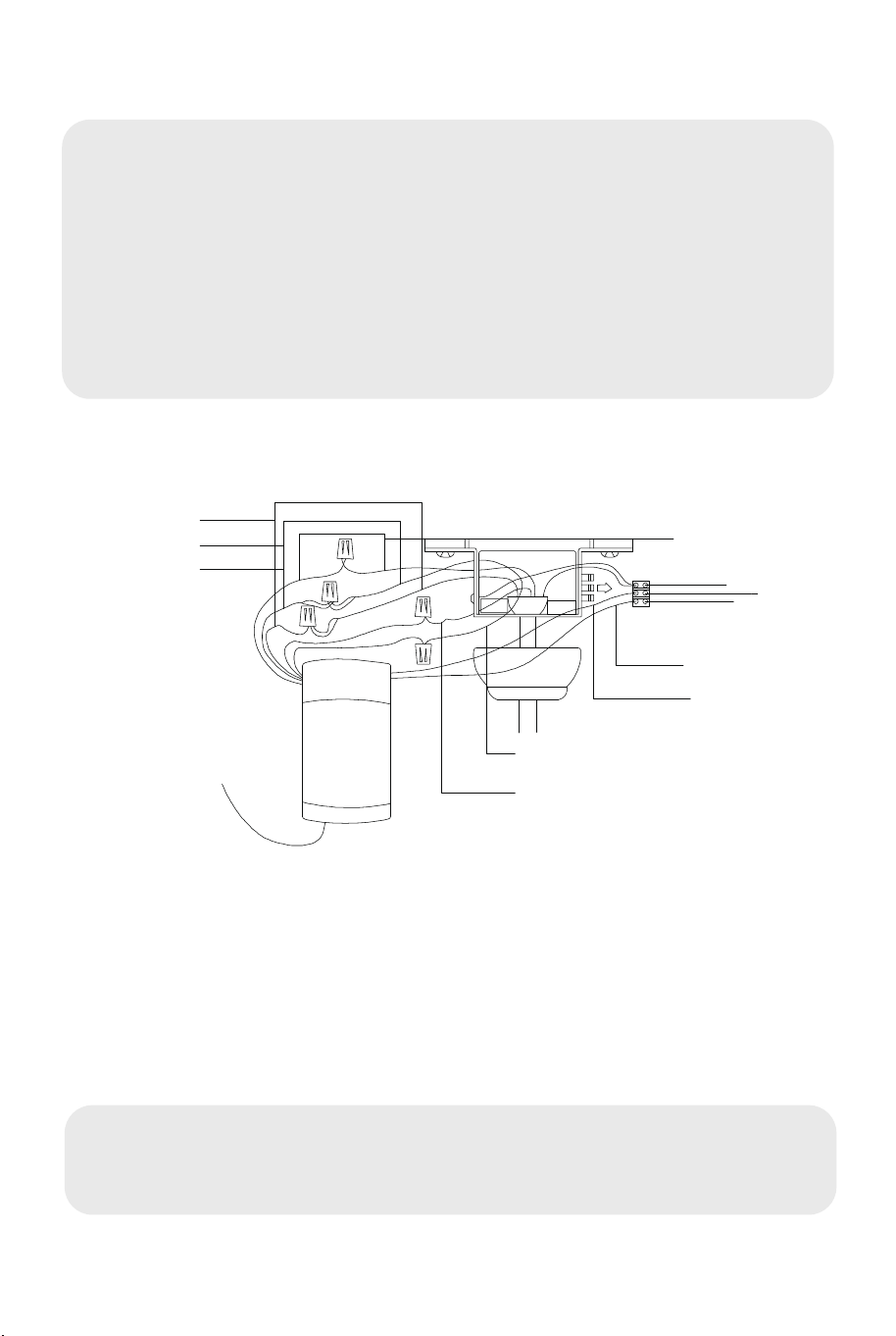
9) Connect the Power Cord
10) The Balance Adjustment of the Fan
Safety Instructions
Fan is installed, if it shakes up and down, please check the screws in blades,
downrod, and the lamp kit if they are fixed. If not, please fix them with screw
driver. lf the fan still shakes, please use the balancing kit stools and check the
instruction of balancing kit inside the carton.
1. In order to reduce the occurrence of electric shock, an all-pole isolating switch
must be installed at the connection between the power supply line and the fan
(switch contacts opening distance should be more than 0.1"). If you lack of electrical
knowledge, ask a qualified technician to install the product.
2. To avoid electrical shock hazard, when installing the ceiling fan, power off before
removing it. It should be installed in the order of earth wire, live line and zero line.
When dismantling, it must be dismantled in the order of zero line, live line and earth
wire.
3. In order to reduce electric shock or prevent from accidents, do not use non-local
speed controller or switches.
4. When installing the ceiling fan, make sure that the screws of each component are
firmly fixed.
5. When the ceiling fan rotates, the blades should not touch anything to avoid
danger.
6. Choose a suitable location to install the ceiling fan, and the ceiling fan blade
should be more than 7.5ft away from the ground to prevent blade collision
accidents.
7. To change the rotation direction of the fan, turn off the product, adjust the
reversing switch, and wait for the blades to stop rotating.
8. For the installation of the ceiling fan and the connection of the power supply,
please read the installation steps of the ceiling fan carefully.
9. Do not directly clean the ceiling fan blades with clean water or detergent. To
remove dust, use a dry cloth or a slightly damp cloth. Before cleaning the ceiling
fan, you must disconnect the ceiling fan from the power switch.
2. When the remote control cannot control the controller, please check
whether the battery is loaded correctly;
3. Too low battery voltage will affect the distance of remote control and
may cause remote control failure. Please replace the battery in time.
4. When not in use for a long time, please remove the battery of the
remote control;
5. During the installation, the celling cover of the fan shall not compress
all the wires, which may easily cause the wires to break and short
circuit.
2. Keep ceiling fans clean regularly. Only use a soft brush or a lint—free
cloth to clean it gently. Do not use a damp cloth or other destructive
cleaner.
3. Don't add lubricating oil or lubricant to any part of this product.
Warm Tips: the Maintenance of Ceiling Fans
1. Because the ceiling fan always runs, please check regularly whether
the hanger, fan blade, leaf rack and other parts are loose. If yes, please
fasten them in time to ensure the fan runs with safety.
Tools Needed
• Phillips Screwdriver
• Blade Screwdriver
• Adjustable Pliers or Wrench
• Step Ladder
• Wire Cutter
• Electrical Tape
Motor W(yellow)
G in earth
AC in N
AC in N(white)
AC in L
AC in L(black)
Light L(blue)
Light N(white)
Remote Control
Receiver
A:DC
Motor V(red)
Motor U(grey)
10 11

Please give us a chance to make it right and do better !
Contact our friendly customer service department for help first.
Replacements for missing or damaged parts will be shipped ASAP !
Contact Us!
Do NOT return this item.
CEILING FAN
ES10186US
USER’S MANUAL
THIS INSTRUCTION BOOKLET CONTAINS IMPORTANT SAFETY INFORMATION. PLEASE READ AND KEEP FOR FUTURE REFERENCE.
US office: Fontana UK office: Ipswich AU office: Truganina
DE office: Hamburg
FR office: Saint Vigor d'Ymonville
PL office: Gdańsk
US:cs.us@costway.com
UK:cs.uk@costway.com