THIS INSTRUCTION BOOKLET CONTAINS IMPORTANT SAFETY INFORMATION. PLEASE READ AND KEEP FOR FUTURE REFERENCE.
EN
DE
FR
ES
IT
PL
With your inspiring rating, COSTWAY will be more consistent to offer you EASY
SHOPPING EXPERIENCE, GOOD PRODUCTS and EFFICIENT SERVICE!
Mit Ihrer inspirierenden Bewertung wird COSTWAY konsistenter sein, um Ihnen EIN
SCHÖNES EINKAUFSERLEBNIS, GUTE PRODUKTE und EFFIZIENTEN SERVICE zu
bieten!
Avec votre évaluation inspirante, COSTWAY continuera à fournir une EXPÉRIENCE
D’ACHAT PRATIQUE, des PRODUITS DE QUALITÉ et un SERVICE EFFICACE !
Con su calificación inspiradora, COSTWAY será más consistente para ofrecerle
EXPERIENCIA DE COMPRA FÁCIL, BUENOS PRODUCTOS y SERVICIO EFICIENTE.
Con la tua valutazione incoraggiante, COSTWAY sarà più coerente per offrirti
ESPERIENZA DI ACQUISTO FACILE, BUONI PRODOTTI e SERVIZIO EFFICIENTE!
Dzięki twojej opinii COSTWAY będzie mógł oferować jeszcze WYGODNIEJSZE
ZAKUPY, LEPSZE PRODUKTY i SPRAWNIEJSZĄ OBSŁUGĘ KLIENTA.
US office: Fontana UK office: Ipswich AU office: Truganina
DE office: Hamburg
FR office: Saint Vigor d'Ymonville
PL office: Gdańsk
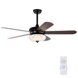
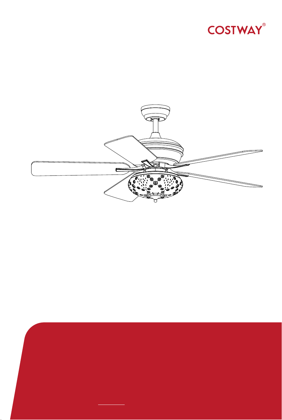
Ceiling Fan
ES10099US
USER’S MANUAL
EN
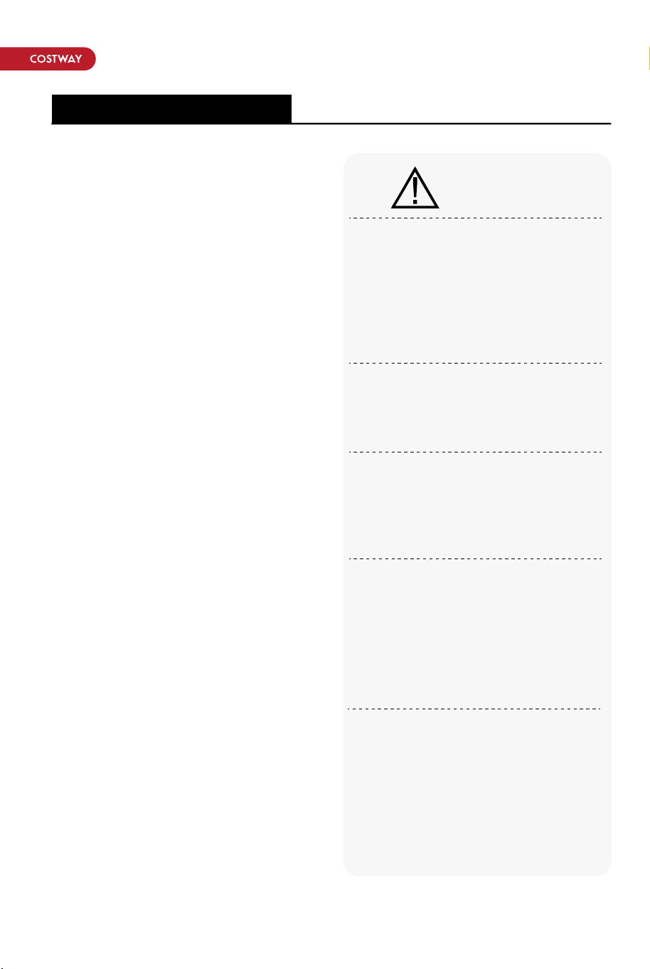
Safety Information
1.To reduce the risk of electric
shock,the electricity has been
turned off at the circuit breaker or
fuse box before begin.
2.The outlet box and support
structure must be securely
mounted and capable of reliably
supporting 35lbs(15.9kg).
3.The fan must be mounted with a
minimum of 2.3m(7.5ft) clearance
from the trailing edge of the blades
to the floor.
4.Do not operate the reversing
switch while the fan blades are in
motion. You must turn the fan off
and stop the blades before you
reverse the blade direction.
5.Do not place objects in the path
of the blades.
6.To avoid personal injury or
damage to the fan and other
items, please be careful when
walking around or cleaning the fan.
7.After making electrical
connections , spliced conductors
should be turned upward and
pushed carefully up into the outlet
box. The wires should be spread
apart with the grounded
conductor and the
equipment-grounding conductor on
one side of the outlet box.
8.All setscrews must be checked
and retightened where necessary
before installation.
To reduce the risk of personal
injury, do not bend the blade
brackets (also referred to as
flanges) during assembly or after
installation. Do not insert objects
in the path of the
blades.
Remove the rubber motor stops
on the bottom of the fan before
installing the blades or testing the
motor.
To reduce the risk of fire or
electric shock,do not use this fan
with any solid-statespeed control
device.
To avoid possible electric shock,
turn the electricity off at the main
fuse box before
wiring.If you feel you do not have
enough electrical wiring
knowledge or experience,contact
a licensed electrician.
To reduce the risk of fire, electric
shock, or personal injury, mount
to outlet box marked "Acceptable
for fan support of 35 lbs.(15.9
kg)or less" and use the screws
provided with the outletbox.
WARNING:
Pre-Installation
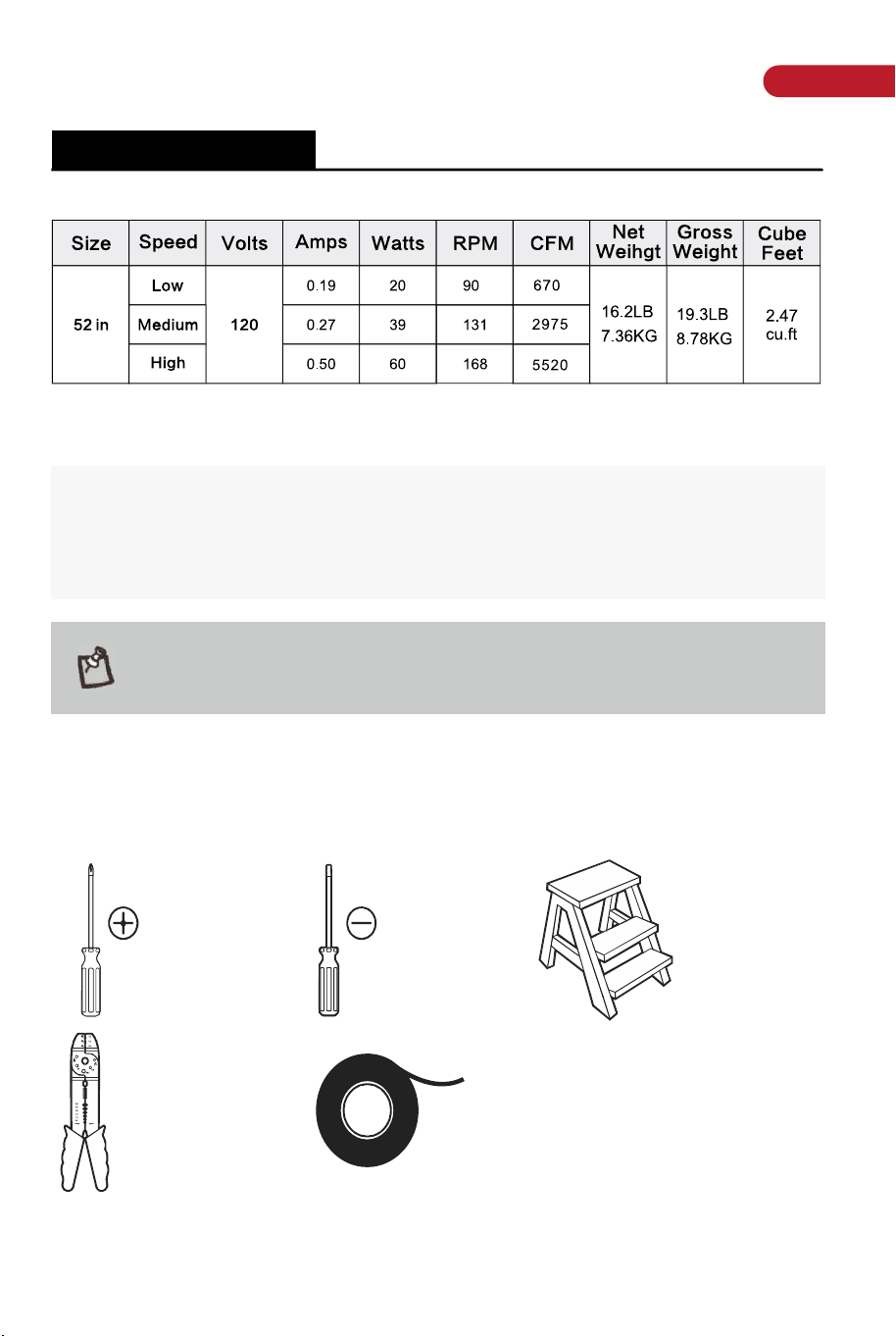
SPECIFICATION
The above data are for reference only, actually the motor speed of each
ceiling fan is a little different. Any product is subject to actual products
as standard.
NOTE: These are a pproximate measures. They do notinclude the
amps and wattage used by the light kit.
Specifications & measurements shown are subject to± 5% variations.
TOOLS REQUIRED
Phillips
screwdriver
Wire stripper
Flat blade
screwdriver
Electrical tape
Step ladder
02 03
EN
Safety Information
1.To reduce the risk of electric
shock,the electricity has been
turned off at the circuit breaker or
fuse box before begin.
2.The outlet box and support
structure must be securely
mounted and capable of reliably
supporting 35lbs(15.9kg).
3.The fan must be mounted with a
minimum of 2.3m(7.5ft) clearance
from the trailing edge of the blades
to the floor.
4.Do not operate the reversing
switch while the fan blades are in
motion. You must turn the fan off
and stop the blades before you
reverse the blade direction.
5.Do not place objects in the path
of the blades.
6.To avoid personal injury or
damage to the fan and other
items, please be careful when
walking around or cleaning the fan.
7.After making electrical
connections , spliced conductors
should be turned upward and
pushed carefully up into the outlet
box. The wires should be spread
apart with the grounded
conductor and the
equipment-grounding conductor on
one side of the outlet box.
8.All setscrews must be checked
and retightened where necessary
before installation.
To reduce the risk of personal
injury, do not bend the blade
brackets (also referred to as
flanges) during assembly or after
installation. Do not insert objects
in the path of the
blades.
Remove the rubber motor stops
on the bottom of the fan before
installing the blades or testing the
motor.
To reduce the risk of fire or
electric shock,do not use this fan
with any solid-statespeed control
device.
To avoid possible electric shock,
turn the electricity off at the main
fuse box before
wiring.If you feel you do not have
enough electrical wiring
knowledge or experience,contact
a licensed electrician.
To reduce the risk of fire, electric
shock, or personal injury, mount
to outlet box marked "Acceptable
for fan support of 35 lbs.(15.9
kg)or less" and use the screws
provided with the outletbox.
WARNING:
Pre-Installation
SPECIFICATION
The above data are for reference only, actually the motor speed of each
ceiling fan is a little different. Any product is subject to actual products
as standard.
NOTE: These are a pproximate measures. They do notinclude the
amps and wattage used by the light kit.
Specifications & measurements shown are subject to± 5% variations.
TOOLS REQUIRED
Phillips
screwdriver
Wire stripper
Flat blade
screwdriver
Electrical tape
Step ladder
02 03
EN
Pre-Installation(continued)Pre-Installation(continued)
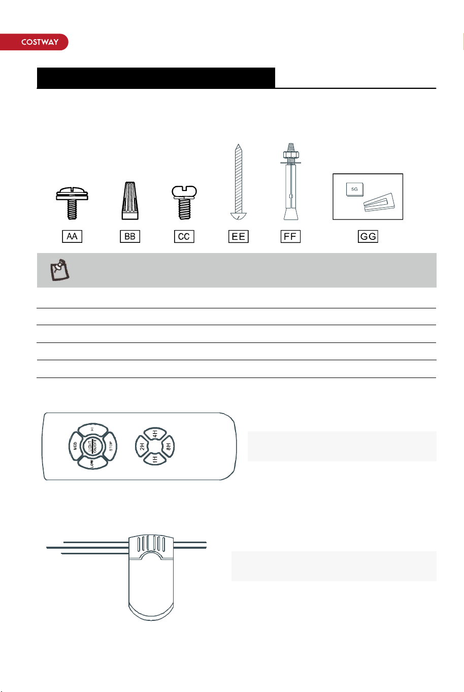
HARDWARE INCLUDED
components table
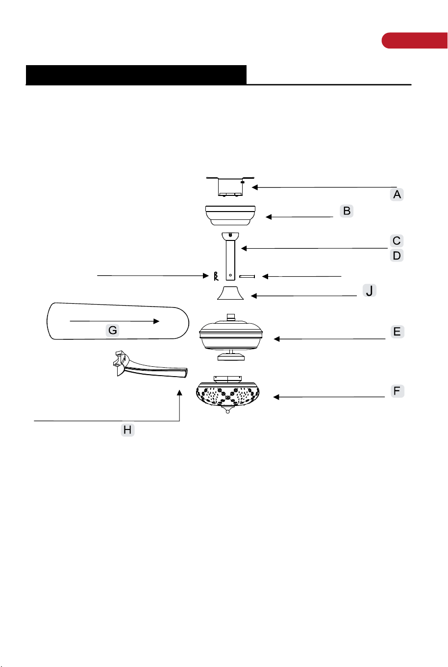
PACKAGE ONTENTS
NOTE: Hardware not shown to actual size
AA
BB
CC
EE
FF
GG
Remote control (Transmitter)x1
Remote control (receiver)x1
16
3
1
4
2
1
Blade attachment screw and fiber washer
Plastic wire nut (not to scale)
Blade arm screw and lock washer
Mounting screws
Expansion Bolts
Balanced parts package
Slide-on mounting bracket
Canopy
13cmBall/downrod assembly
Hanging Pin
Coupling cover
Fan-motor assembly
Light kit fitter assembly
"R"Locking Pin
Blade (5PCS)
25.5cmBall/downrod assembly(standby)
Arm(with pre-installed screws)
5pcs
Please check whether above accessories are completed or
not?Yes,and install.
04 05
EN
Pre-Installation(continued)Pre-Installation(continued)
HARDWARE INCLUDED
components table
PACKAGE ONTENTS
NOTE: Hardware not shown to actual size
AA
BB
CC
EE
FF
GG
Remote control (Transmitter)x1
Remote control (receiver)x1
16
3
1
4
2
1
Blade attachment screw and fiber washer
Plastic wire nut (not to scale)
Blade arm screw and lock washer
Mounting screws
Expansion Bolts
Balanced parts package
Slide-on mounting bracket
Canopy
13cmBall/downrod assembly
Hanging Pin
Coupling cover
Fan-motor assembly
Light kit fitter assembly
"R"Locking Pin
Blade (5PCS)
25.5cmBall/downrod assembly(standby)
Arm(with pre-installed screws)
5pcs
Please check whether above accessories are completed or
not?Yes,and install.
04 05
EN
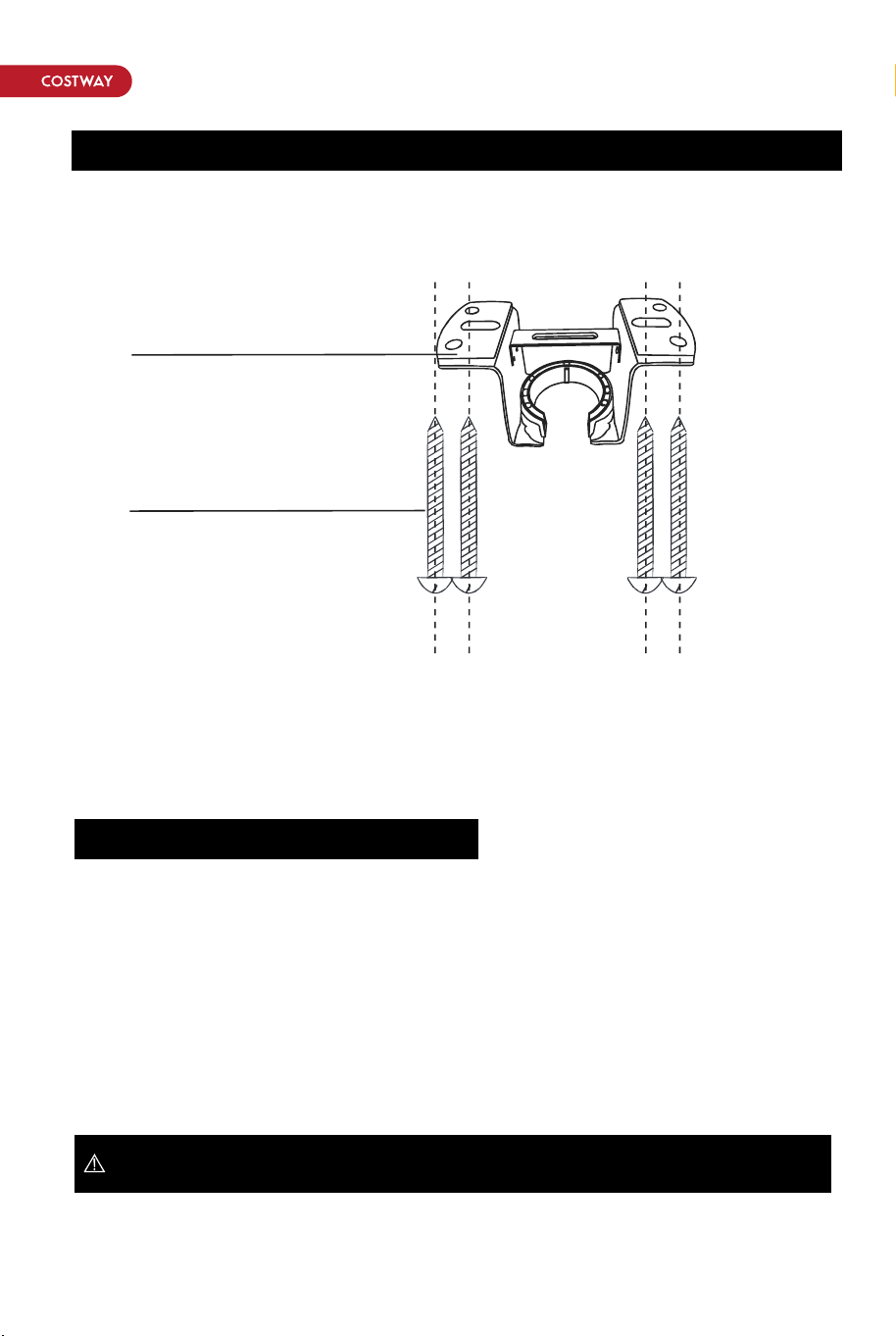
Installation of the hanging bracket (suspension part)
WOODEN CEILING
CONCRETE CEILING
SWITCH OFFTHE ELECTRICAL MAINSATTHE CIRCUIT
BREAKER FUSE Box.
SWITCH OFF THE ELECTRICAL MAINS AT THE CIRCUIT
BREAKER FUSE Box
STEP 1 A-WOODEN CEILING
STEP 2 A-CONCRETE CEILING
IMPORTANT: SCREWS MUST BE TIGHTENED TILL SNUG
IMPORTANT: SCREWS MUST BE TIGHTENED TILL SNUG
Mounting Bracket<A>
Self tapping screw<B>
For wooden ceiling, use wood screw to drill on the wooden beam or the
"junction box" to fix the hanging bracket (selection is made according to
actual requirements of the customers).
1) Use the Mounting Bracket (A) as a guide, mark the spots where the 4
Self Tapping Screws (B) will be drilled.
2) Remove the Mounting Bracket (A), drill 4 holes for 3MM diameter, install
the mounting bracket onto wooden ceiling with the 4 Self Tapping Screws
(B).
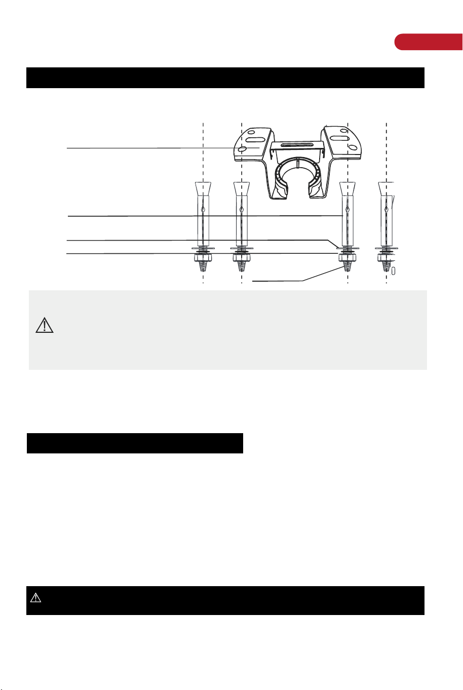
Installation of the hanging bracket (suspension part)
Mounting Bracket<A>
Expension Bolts<B>
Flat Washers <C>
Spring Washers<D>
Nuts<E>
Note: According to the ceiling of different materials, use different
screws to fix the hanging bracket.Don't fix the hanging bracket on
the wood ceiling less than 12MM to prevent danger caused by
loosening of screws.
After the hanging bracket is completed, ensure that it can withstand
the tension test of more than 150 LBS for safety.
For concrete ceiling, use the percussion bit with diameter 8mm to drill holes
according to the length of expansion screws. Then use the attached
expansion screws to fix the hanging bracket onto the ceiling (selection is
made according to actual requirements of the customers).
1 )Use the Mounting Bracket (A) as a guide, mark the spots where the 4
Expansion Bolts (B) will be drilled.
2)Remove the Mounting Bracket (AA), drill 4 holes and insert 4 Expansion
Bolts (B) into the concrete ceiling, install the mounting bracket and secure
with Flat Washers (C), Spring Washers (D) and Nuts (E)
06 07
EN
Installation of the hanging bracket (suspension part)
WOODEN CEILING
CONCRETE CEILING
SWITCH OFFTHE ELECTRICAL MAINSATTHE CIRCUIT
BREAKER FUSE Box.
SWITCH OFF THE ELECTRICAL MAINS AT THE CIRCUIT
BREAKER FUSE Box
STEP 1 A-WOODEN CEILING
STEP 2 A-CONCRETE CEILING
IMPORTANT: SCREWS MUST BE TIGHTENED TILL SNUG
IMPORTANT: SCREWS MUST BE TIGHTENED TILL SNUG
Mounting Bracket<A>
Self tapping screw<B>
For wooden ceiling, use wood screw to drill on the wooden beam or the
"junction box" to fix the hanging bracket (selection is made according to
actual requirements of the customers).
1) Use the Mounting Bracket (A) as a guide, mark the spots where the 4
Self Tapping Screws (B) will be drilled.
2) Remove the Mounting Bracket (A), drill 4 holes for 3MM diameter, install
the mounting bracket onto wooden ceiling with the 4 Self Tapping Screws
(B).
Installation of the hanging bracket (suspension part)
Mounting Bracket<A>
Expension Bolts<B>
Flat Washers <C>
Spring Washers<D>
Nuts<E>
Note: According to the ceiling of different materials, use different
screws to fix the hanging bracket.Don't fix the hanging bracket on
the wood ceiling less than 12MM to prevent danger caused by
loosening of screws.
After the hanging bracket is completed, ensure that it can withstand
the tension test of more than 150 LBS for safety.
For concrete ceiling, use the percussion bit with diameter 8mm to drill holes
according to the length of expansion screws. Then use the attached
expansion screws to fix the hanging bracket onto the ceiling (selection is
made according to actual requirements of the customers).
1 )Use the Mounting Bracket (A) as a guide, mark the spots where the 4
Expansion Bolts (B) will be drilled.
2)Remove the Mounting Bracket (AA), drill 4 holes and insert 4 Expansion
Bolts (B) into the concrete ceiling, install the mounting bracket and secure
with Flat Washers (C), Spring Washers (D) and Nuts (E)
06 07
EN
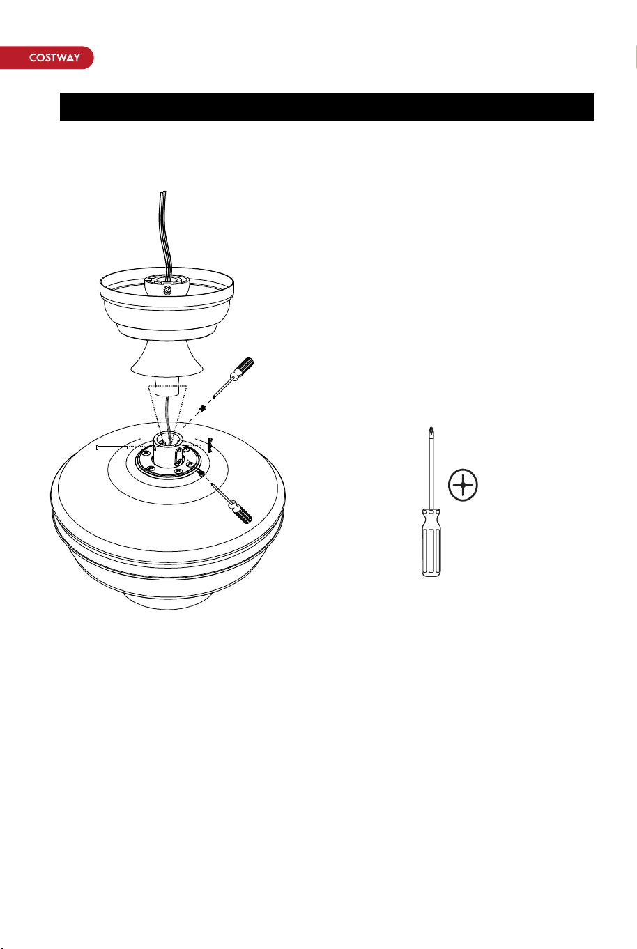
Install the hanging part of the ceiling fan
Assembly - Hanging the Fan(continued)
1. Thread the suspender through the suspended clock and coupling cover.
2.Then insert the tail of the suspender from the lifting head of the motor.
3.After the lateral pin is threaded out from the suspended head position,
insert R type pin.
4.Tighten the lifting head screws.
5.Hang the fan of the hanging pipe into the hanger.
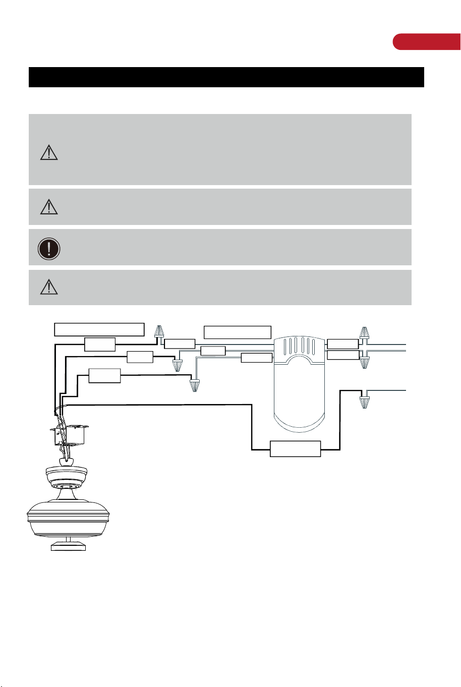
a.The motor white wire to the white " to motor N" wire
from Receiver with a wire nut.
b.The motor black wire to the black"to motor L" wire
from Receiver with a wire nut.
c.The lamp blue wire to the blue"to Light" wire from
Receiver with a wire nut.
d.The white wire from Outlet Box to the red"AC in N"
wire from Receiver with a wire nut.
e.The black wire from Outlet Box to the red“AC in L" wire from Receiver with
a wire nut.
Connect the supply ground wire to green ground wire from canopy and the
green ground wire from the hanger bracket together using a wire nut.
Tuck all wire nuts and wires carefully up into the Outlet Box,EXCEPT
antenna,which should remain outside Outlet Box
1.Making the electrical connections
Phillips
screwdriver
WARNING: Each wire not supplied with this fan is designed to
accept up to one 12-gauge house wire and two wires from the
fan.lf you have larger than 12-gauge house wiring or more
than one house wire to connect to the fan wiring, consult an
electrician for the proper size wire nuts to use.
WARNING: Remove the rubber motor stops on the bottom of
fan before installing the blades or testing the motor.
IMPORTANT: Use the plastic wire connectors supplied with your
fan. Secure the connectors with electrical tape and ensure there
are no loose strands or connections.
WARNING: Ensure that the wires are fifirmly connected
without looseness.
From CEILING FAN
From controller
Ground wire
FOR AC IN L
FOR AC IN N
GREEN
BLACK
BLACK
BLACK
BLUE
BLUE
WHITE
WHITE
WHITE
08 09
EN
Install the hanging part of the ceiling fan
Assembly - Hanging the Fan(continued)
1. Thread the suspender through the suspended clock and coupling cover.
2.Then insert the tail of the suspender from the lifting head of the motor.
3.After the lateral pin is threaded out from the suspended head position,
insert R type pin.
4.Tighten the lifting head screws.
5.Hang the fan of the hanging pipe into the hanger.
a.The motor white wire to the white " to motor N" wire
from Receiver with a wire nut.
b.The motor black wire to the black"to motor L" wire
from Receiver with a wire nut.
c.The lamp blue wire to the blue"to Light" wire from
Receiver with a wire nut.
d.The white wire from Outlet Box to the red"AC in N"
wire from Receiver with a wire nut.
e.The black wire from Outlet Box to the red“AC in L" wire from Receiver with
a wire nut.
Connect the supply ground wire to green ground wire from canopy and the
green ground wire from the hanger bracket together using a wire nut.
Tuck all wire nuts and wires carefully up into the Outlet Box,EXCEPT
antenna,which should remain outside Outlet Box
1.Making the electrical connections
Phillips
screwdriver
WARNING: Each wire not supplied with this fan is designed to
accept up to one 12-gauge house wire and two wires from the
fan.lf you have larger than 12-gauge house wiring or more
than one house wire to connect to the fan wiring, consult an
electrician for the proper size wire nuts to use.
WARNING: Remove the rubber motor stops on the bottom of
fan before installing the blades or testing the motor.
IMPORTANT: Use the plastic wire connectors supplied with your
fan. Secure the connectors with electrical tape and ensure there
are no loose strands or connections.
WARNING: Ensure that the wires are fifirmly connected
without looseness.
From CEILING FAN
From controller
Ground wire
FOR AC IN L
FOR AC IN N
GREEN
BLACK
BLACK
BLACK
BLUE
BLUE
WHITE
WHITE
WHITE
08 09
EN
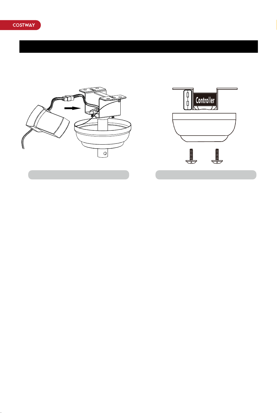
1.Carefully push the canopy to the
bottom of the mounting bracket,
make two sliding holes aligned to
the two prominent screws on the
mounting bracket, and then turn
clockwise until tight.
2.Push the canopy ring to the
bottom of the canopy,slide the
inner holes aligned to the two
prominent screws on the mounting
bracket again, and turn the canopy
ring clockwise until tight.
1. Remove the mounting bracket
from the canopy by loosening the
two canopy screws locatedin the
L shaped slots.
2. Remove and save the two
canopy screws in the round holes.
This will enable you to remove
the mountingbracket
Phillips
screwdriver
Phillips
screwdriver
Assembly - Hanging the Fan( continued)
Install remote control
Preparing for mounting
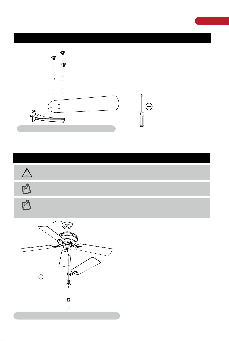
Assembly - Attaching the Fan Blades
Assembly - Attaching the Fan Blades
Attaching the blades to the arms
1:Pass the red washer through the screw.
2:Tighten the screw through the blade and tighten it on the arms.
3:Repeat the above steps to tighten the four sets of blades.
WARNING: Remove the rubber motor stops on the bottom of the
fan before installing the blades or testing the motor.
NOTE: Your fan blades are reversible.Select the blade side finish
which best accentuates your decor.
NOTE: Your fan features revolutionary advancements for quick and
easy blade installation.Including an alignment post and captive
blade arm screws.
1: Fasten the arm to the
fan-motor assembly by
inserting the alignment post in
the slot on the bottom of the
motor and tightening the
pre-installed arm screws.
2: Repeat this step for the
remaining blade assemblies.
Fastening the blade arms to the motor
10 11
Preparing for mounting
1. Attaching the blades to the arms
2. Fastening the blade
arms to the motor
EN
1.Carefully push the canopy to the
bottom of the mounting bracket,
make two sliding holes aligned to
the two prominent screws on the
mounting bracket, and then turn
clockwise until tight.
2.Push the canopy ring to the
bottom of the canopy,slide the
inner holes aligned to the two
prominent screws on the mounting
bracket again, and turn the canopy
ring clockwise until tight.
1. Remove the mounting bracket
from the canopy by loosening the
two canopy screws locatedin the
L shaped slots.
2. Remove and save the two
canopy screws in the round holes.
This will enable you to remove
the mountingbracket
Phillips
screwdriver
Phillips
screwdriver
Assembly - Hanging the Fan( continued)
Install remote control
Preparing for mounting
Assembly - Attaching the Fan Blades
Assembly - Attaching the Fan Blades
Attaching the blades to the arms
1:Pass the red washer through the screw.
2:Tighten the screw through the blade and tighten it on the arms.
3:Repeat the above steps to tighten the four sets of blades.
WARNING: Remove the rubber motor stops on the bottom of the
fan before installing the blades or testing the motor.
NOTE: Your fan blades are reversible.Select the blade side finish
which best accentuates your decor.
NOTE: Your fan features revolutionary advancements for quick and
easy blade installation.Including an alignment post and captive
blade arm screws.
1: Fasten the arm to the
fan-motor assembly by
inserting the alignment post in
the slot on the bottom of the
motor and tightening the
pre-installed arm screws.
2: Repeat this step for the
remaining blade assemblies.
Fastening the blade arms to the motor
10 11
Preparing for mounting
1. Attaching the blades to the arms
2. Fastening the blade
arms to the motor

THIS INSTRUCTION BOOKLET CONTAINS IMPORTANT SAFETY INFORMATION. PLEASE READ AND KEEP FOR FUTURE REFERENCE.
EN
DE
FR
ES
IT
PL
With your inspiring rating, COSTWAY will be more consistent to offer you EASY
SHOPPING EXPERIENCE, GOOD PRODUCTS and EFFICIENT SERVICE!
Mit Ihrer inspirierenden Bewertung wird COSTWAY konsistenter sein, um Ihnen EIN
SCHÖNES EINKAUFSERLEBNIS, GUTE PRODUKTE und EFFIZIENTEN SERVICE zu
bieten!
Avec votre évaluation inspirante, COSTWAY continuera à fournir une EXPÉRIENCE
D’ACHAT PRATIQUE, des PRODUITS DE QUALITÉ et un SERVICE EFFICACE !
Con su calificación inspiradora, COSTWAY será más consistente para ofrecerle
EXPERIENCIA DE COMPRA FÁCIL, BUENOS PRODUCTOS y SERVICIO EFICIENTE.
Con la tua valutazione incoraggiante, COSTWAY sarà più coerente per offrirti
ESPERIENZA DI ACQUISTO FACILE, BUONI PRODOTTI e SERVIZIO EFFICIENTE!
Dzięki twojej opinii COSTWAY będzie mógł oferować jeszcze WYGODNIEJSZE
ZAKUPY, LEPSZE PRODUKTY i SPRAWNIEJSZĄ OBSŁUGĘ KLIENTA.
US office: Fontana UK office: Ipswich AU office: Truganina
DE office: Hamburg
FR office: Saint Vigor d'Ymonville
PL office: Gdańsk
Ceiling Fan
ES10099US
USER’S MANUAL