THIS INSTRUCTION BOOKLET CONTAINS IMPORTANT SAFETY INFORMATION. PLEASE READ AND KEEP FOR FUTURE REFERENCE.
EN
DE
FR
ES
IT
PL
With your inspiring rating, COSTWAY will be more consistent to offer you EASY
SHOPPING EXPERIENCE, GOOD PRODUCTS and EFFICIENT SERVICE!
Mit Ihrer inspirierenden Bewertung wird COSTWAY konsistenter sein, um Ihnen EIN
SCHÖNES EINKAUFSERLEBNIS, GUTE PRODUKTE und EFFIZIENTEN SERVICE zu
bieten!
Avec votre évaluation inspirante, COSTWAY continuera à fournir une EXPÉRIENCE
D’ACHAT PRATIQUE, des PRODUITS DE QUALITÉ et un SERVICE EFFICACE !
Con su calificación inspiradora, COSTWAY será más consistente para ofrecerle
EXPERIENCIA DE COMPRA FÁCIL, BUENOS PRODUCTOS y SERVICIO EFICIENTE.
Con la tua valutazione incoraggiante, COSTWAY sarà più coerente per offrirti ESPE-
RIENZA DI ACQUISTO FACILE, BUONI PRODOTTI e SERVIZIO EFFICIENTE!
Dzięki twojej opinii COSTWAY będzie mógł oferować jeszcze WYGODNIEJSZE
ZAKUPY, LEPSZE PRODUKTY i SPRAWNIEJSZĄ OBSŁUGĘ KLIENTA.
US office: Fontana UK office: Ipswich AU office: Truganina
DE office: Hamburg
FR office: Saint Vigor d'Ymonville
PL office: Gdańsk
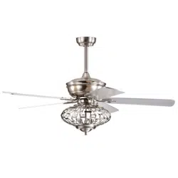
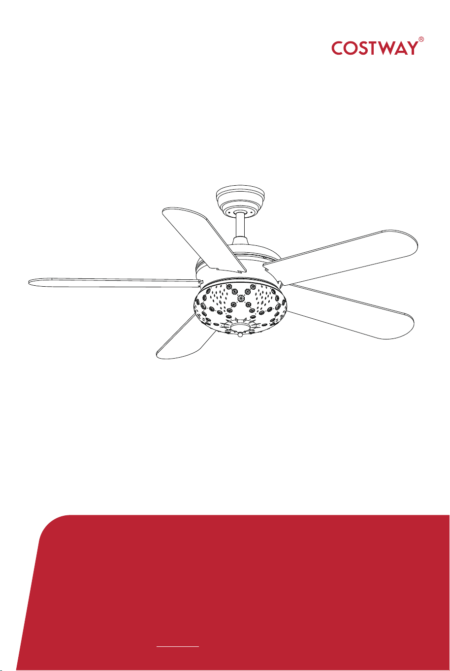
52" CEILING FAN
ES10100US
USER’S MANUAL

HW61891
02 03
Safety Information
1. To reduce the risk of electric shock, the electricity has been turned
off at the circuit breaker or fuse box before begin.
2. All wiring must be in accordance with the National Electrical Code
NASI/NFPA 70-1999 and local electrical codes.Electrical installation
should be performed by a qualified licensed electrician.
3. The outlet box and support structure must be securely mounted and
capable of reliably supporting 35 lbs. (15.9kg). Use only UL listed outlet
boxes marked "Acceptable for Fan Support of 35 lbs (15.9kg) or less."
4. The fan must be mounted with a minimum of 7ft (2m) clearance
from the trailing edge of the blades to the floor.
5. Do not operate the reversing switch while the fan blades are in
motion. You must turn the fan off and stop the blades before you
reverse the blade direction.
6. Do not place objects in the path of the blades.
7. To avoid personal injury or damage to the fan and other items,
please be careful when working around or cleaning the fan.
8. Electrical diagrams are for reference only. Light kits that are not
packed with the fan must be UL-listed and marked suitable for use with
the model fan you are installing. Switches must be UL General Use
Switches. Refer to the instructions packaged with the light kits and
switches for proper assembly.
9. After making electrical connections, spliced conductors should be
turned upward and pushed carefully up into the outlet box. The wires
should be spread apart with the grounded conductor and the
equipment-grounding conductor on one side of the outlet box.
10. All setscrews must be checked and retightened where necessary
before installation.
• To reduce the risk of personal injury,do not bend the blade brackets
(also referred to as flanges) during assembly or after installation. Do
not insert objects in the path of the blades.
WARNING
• Remove the rubber motor stops on the bottom of the fan before
installing the blades or testing the motor.
• To reduce the risk or fire or electric shock,do not use this fan with
any solid-state speed control device.
• To avoid possible electric shock, turn the electricity off at the main
fuse box before wiring. If you feel you do not have enough electrical
wiring knowledge or experience, contact a licensed electrician.
• Electrical diagrams are for reference only. Optional use of any light
kit shall be UL-listed and marked suitable for use with this fan.
• To reduce the risk of fire, electric shock,or personal injury, mount to
outlet box marked"Acceptable for fan support of 35 lbs. (15.9 kg)or
less " and use the screws provided with the outlet box.
04 05
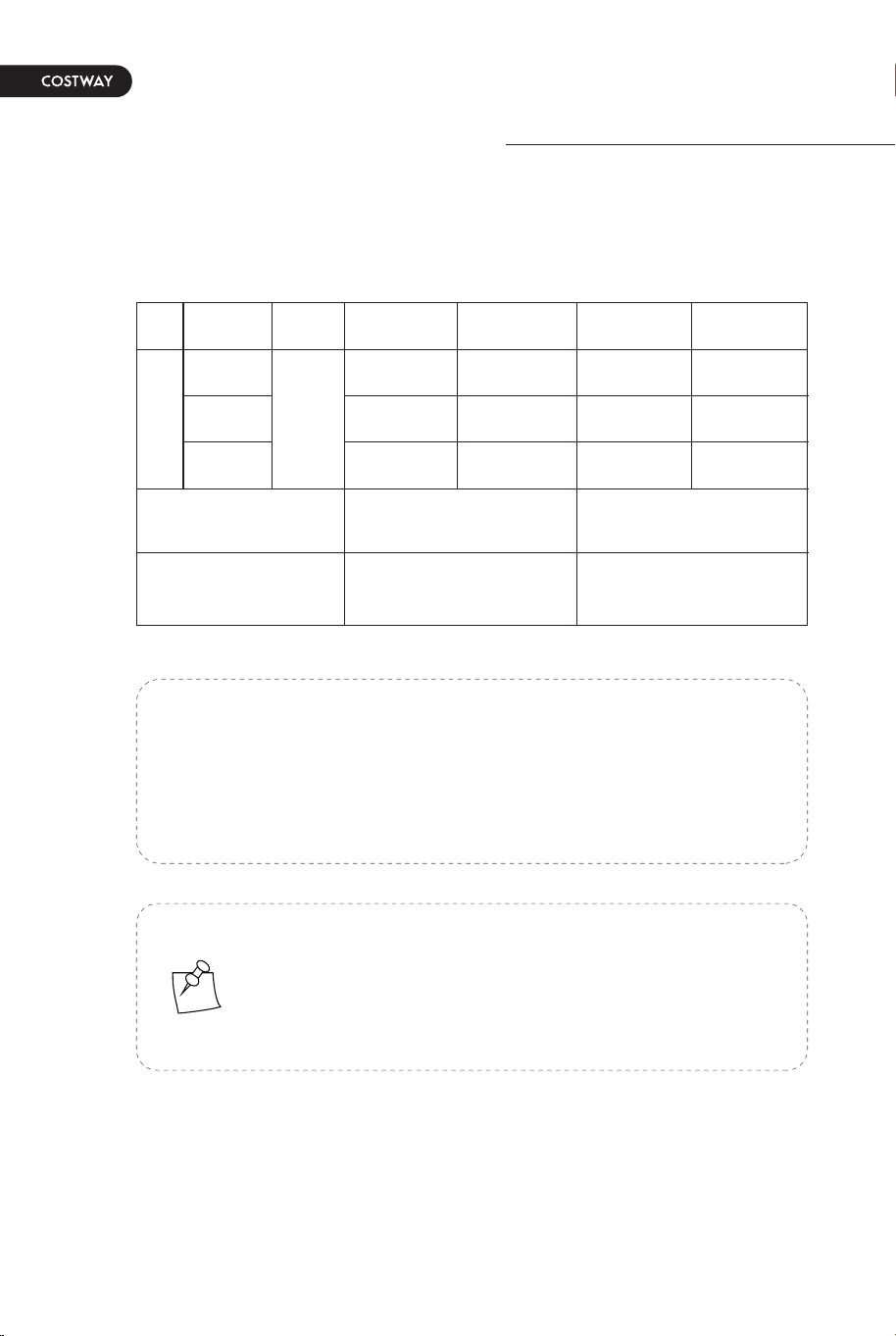
The above data are for reference only, actually the motor speed
of each ceiling fan is a little different. Any products are subject to
actual products as standard.
NOTE: These are approximate measures.They do not
include the amps and wattage used by the light kit.
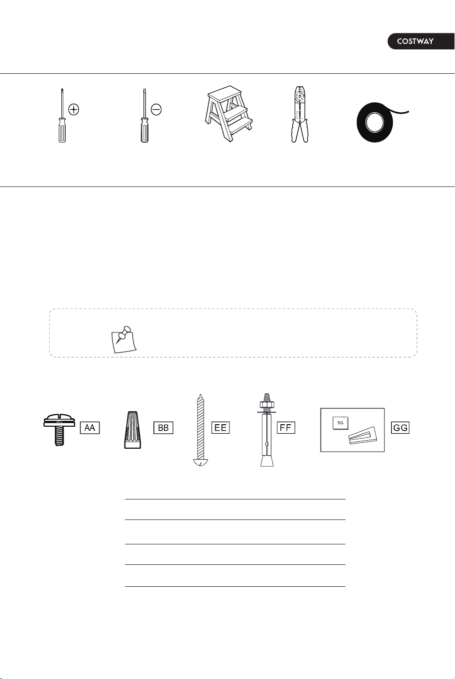
TOOLS REQUIRED
HARDWARE INCLUDED
HW61891
Pre-Installation
SPECIFICATION
Size Volts Amps Watts RPM CFM
Net Weight Gross Weight Cubic Feet
52in 120
16.71LB
7.58KG
19.84LB
9.00KG
2.47 cu.ft
Speed
Low
Medium
High
0.19
0.27
0.50
20
39
60
90
131
180
670
2975
5520
NOTE: Hardware not shown to actual size.
Specifications & measurements shown are subject to ±5% variations.
components table
Phillips
screwdriver
Flat blade
screwdriver
Step
ladder
AA
BB
EE
FF
GG
Wire
stripper
Electrical
tape
Blade attachment screw and fiber washer
Plastic wire nut (not to scale)
Mounting screws
Expansion bolts
Balanced parts package
04 05
The above data are for reference only, actually the motor speed
of each ceiling fan is a little different. Any products are subject to
actual products as standard.
NOTE: These are approximate measures.They do not
include the amps and wattage used by the light kit.
TOOLS REQUIRED
HARDWARE INCLUDED
HW61891
Pre-Installation
SPECIFICATION
Size Volts Amps Watts RPM CFM
Net Weight Gross Weight Cubic Feet
52in 120
16.71LB
7.58KG
19.84LB
9.00KG
2.47 cu.ft
Speed
Low
Medium
High
0.19
0.27
0.50
20
39
60
90
131
180
670
2975
5520
NOTE: Hardware not shown to actual size.
Specifications & measurements shown are subject to ±5% variations.
components table
Phillips
screwdriver
Flat blade
screwdriver
Step
ladder
AA
BB
EE
FF
GG
Wire
stripper
Electrical
tape
Blade attachment screw and fiber washer
Plastic wire nut (not to scale)
Mounting screws
Expansion bolts
Balanced parts package
06 07
Installation of the hanging
bracket (suspension part)
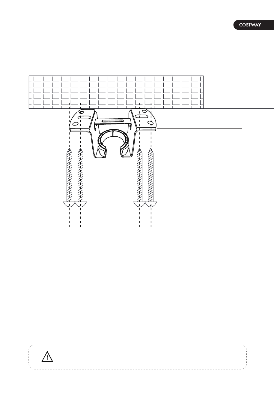
WOODEN CEILING
PACKAGE CONTENTS
For wooden ceiling, use wood screw to drill on the wooden beam or the
"junction box" to fix the hanging bracket (selection is made according to
actual requirements of the customers).
SWITCH OFF THE ELECTRICAL MAINS AT THE CIRCUIT BREAKER FUSE BOX.
1)Use the Mounting Bracket (A) as a guide, mark the spots where the 4 Self
Tapping Screws (B) will be drilled.
2)Remove the Mounting Bracket (A), drill 4 holes for 3MM diameter, install the
mounting bracket onto wooden ceiling with the 4 Self Tapping Screws (B).
Mounting
Bracket<A>
STEP 1A-WOODEN CEILING
Self tapping
screw<B>
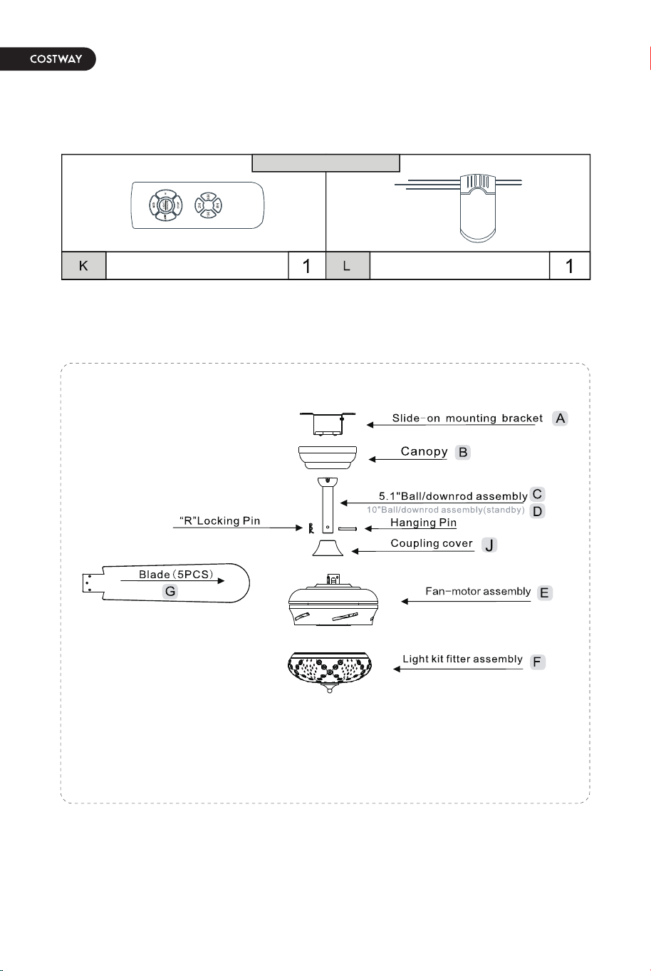
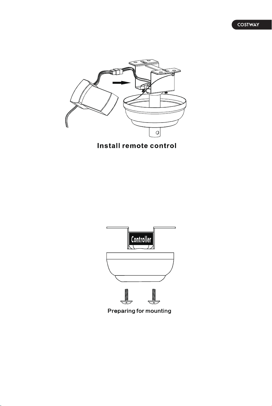
Remote control(Transmitter) Remote control(receiver)
remote control<ONLY>
IMPORTANT : SCREWS MUST BE TIGHTENED TILL SNUG
Pls check whether above accessories are completed or not? Yes, and install.
06 07
Installation of the hanging
bracket (suspension part)
WOODEN CEILING
PACKAGE CONTENTS
For wooden ceiling, use wood screw to drill on the wooden beam or the
"junction box" to fix the hanging bracket (selection is made according to
actual requirements of the customers).
SWITCH OFF THE ELECTRICAL MAINS AT THE CIRCUIT BREAKER FUSE BOX.
1)Use the Mounting Bracket (A) as a guide, mark the spots where the 4 Self
Tapping Screws (B) will be drilled.
2)Remove the Mounting Bracket (A), drill 4 holes for 3MM diameter, install the
mounting bracket onto wooden ceiling with the 4 Self Tapping Screws (B).
Mounting
Bracket<A>
STEP 1A-WOODEN CEILING
Self tapping
screw<B>
Remote control(Transmitter) Remote control(receiver)
remote control<ONLY>
IMPORTANT : SCREWS MUST BE TIGHTENED TILL SNUG
Pls check whether above accessories are completed or not? Yes, and install.
08 09
Install the hanging part of the ceiling fan.
Assembly - Hanging the Fan(continued)
Phillips
screwdriver
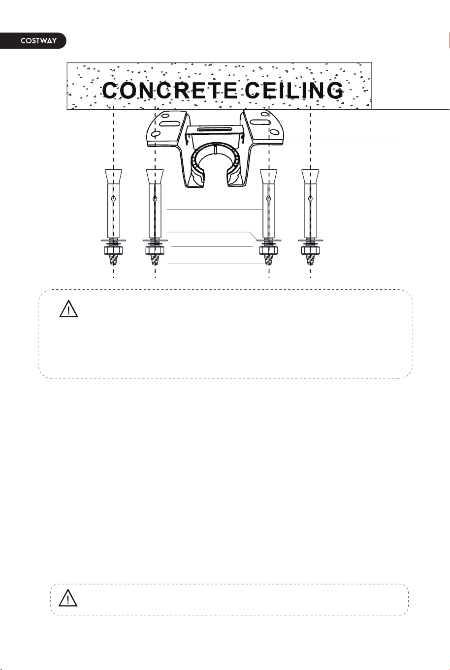
For concrete ceiling, use the percussion bit with diameter 8mm to drill holes
according to the length of expansion screws. Then use the attached expansion
screws to fix the hanging bracket onto the ceiling (selection is made according
to actual requirements of the customers).
SWITCH OFF THE ELECTRICAL MAINS AT THE CIRCUIT BREAKER FUSE BOX.
1)Use the Mounting Bracket (A) as a guide, mark the spots where the 4
Expansion Bolts (B) will be drilled.
2)Remove the Mounting Bracket (A), drill 4 holes and insert 4 Expansion Bolts
(B) into the concrete ceiling, install the mounting bracket and secure with Flat
Washers (C), Spring Washers (D) and Nuts (E).
Expansion Bolts<B>
Nuts<E>
Flat Washers <C>
Spring Washers<D>
1. Install downrod assembly
1. Making the electrical connections
STEP 2A - CONCRETE CEILING
IMPORTANT : SCREWS & NUTS MUST BE TIGHTENED TILL SNUG
Note: According to the ceiling of different materials, use different screws
to fix the hanging bracket.Don't fix the hanging bracket on the wood
ceiling less than 12MM to prevent danger caused by loosening of screws.
After the hanging bracket is completed, ensure that it can withstand the
tension test of more than 68KG for safety.
Mounting
Bracket<A>
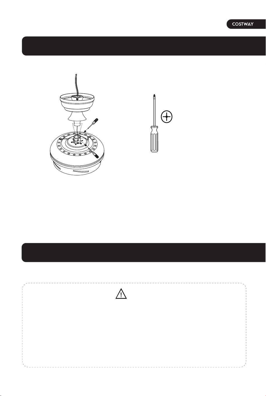
1. Thread the suspender through the suspended clock and coupling cover.
2. Then insert the tail of the suspender from the lifting head of the motor.
3. After the lateral pin is threaded out from the suspended head position,insert
R type pin.
4. Tighten the lifting head screws.
5. Hang the fan of the hanging pipe into the hanger.
• Each wire not supplied with this fan is designed to accept up to one
12-gauge house wire and two wires from the fan. If you have larger than
12-gauge house wiring or more than one house wire to connect to the fan
wiring, consult an electrician for the proper size wire nuts to use.
• Remove the rubber motor stops on the bottom of fan before installing the
blades or testing the motor.
WARNING
08 09
Install the hanging part of the ceiling fan.
Assembly - Hanging the Fan(continued)
Phillips
screwdriver
For concrete ceiling, use the percussion bit with diameter 8mm to drill holes
according to the length of expansion screws. Then use the attached expansion
screws to fix the hanging bracket onto the ceiling (selection is made according
to actual requirements of the customers).
SWITCH OFF THE ELECTRICAL MAINS AT THE CIRCUIT BREAKER FUSE BOX.
1)Use the Mounting Bracket (A) as a guide, mark the spots where the 4
Expansion Bolts (B) will be drilled.
2)Remove the Mounting Bracket (A), drill 4 holes and insert 4 Expansion Bolts
(B) into the concrete ceiling, install the mounting bracket and secure with Flat
Washers (C), Spring Washers (D) and Nuts (E).
Expansion Bolts<B>
Nuts<E>
Flat Washers <C>
Spring Washers<D>
1. Install downrod assembly
1. Making the electrical connections
STEP 2A - CONCRETE CEILING
IMPORTANT : SCREWS & NUTS MUST BE TIGHTENED TILL SNUG
Note: According to the ceiling of different materials, use different screws
to fix the hanging bracket.Don't fix the hanging bracket on the wood
ceiling less than 12MM to prevent danger caused by loosening of screws.
After the hanging bracket is completed, ensure that it can withstand the
tension test of more than 68KG for safety.
Mounting
Bracket<A>
1. Thread the suspender through the suspended clock and coupling cover.
2. Then insert the tail of the suspender from the lifting head of the motor.
3. After the lateral pin is threaded out from the suspended head position,insert
R type pin.
4. Tighten the lifting head screws.
5. Hang the fan of the hanging pipe into the hanger.
• Each wire not supplied with this fan is designed to accept up to one
12-gauge house wire and two wires from the fan. If you have larger than
12-gauge house wiring or more than one house wire to connect to the fan
wiring, consult an electrician for the proper size wire nuts to use.
• Remove the rubber motor stops on the bottom of fan before installing the
blades or testing the motor.
WARNING
10 11
1. Preparing for mounting
1. Carefully push the canopy to the bottom of the mounting bracket, make two
sliding holes aligned to the two prominent screws on the mounting bracket, and
then turn clockwise until tight.
2. Push the canopy ring to the bottom of the canopy, slide the inner holes
aligned to the two prominent screws on the ounting bracketagain, and turn the
canopy ring clockwise until tight.
1. Remove the mounting bracket from the canopy by loosening the two canopy
screws located in the L shaped slots.
2. Remove and save the two canopy screws in the round holes. This will enable
you to remove the mountingbracket
•
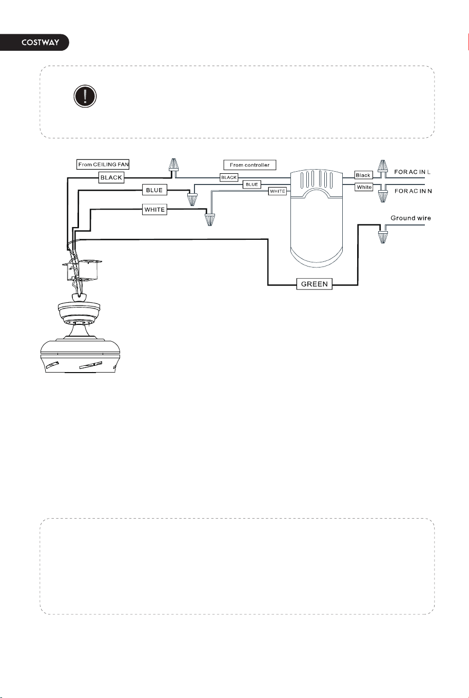
Connect the supply ground wire to green ground wire from canopy and the green
ground wire from the hanger bracket together using a wire nut.
• Tuck all wire nuts and wires carefully up into the Outlet Box, EXCEPT antenna,
which should remain outside Outlet Box.
Use the plastic wire connectors (BB) supplied with your fan.
Secure the connectors with electrical tape and ensure there
are no loose strands or connections.
IMPORTANT
a. The motor white wire to the white “to motor N” wire from Recevier with a wire nut.
b. The motor black wire to the black “to motor L” wire from Receiver with a wire nut.
c. The lamp blue wire to the blue “to Light” wire from Receiver with a wire nut.
d. The white wire from Outlet Box to the red “AC in N” wire from Receiver with a wire nut.
e. The black wire from Outlet Box to the red “AC in L” wire from Receiver with a wire nut.
10 11
1. Preparing for mounting
1. Carefully push the canopy to the bottom of the mounting bracket, make two
sliding holes aligned to the two prominent screws on the mounting bracket, and
then turn clockwise until tight.
2. Push the canopy ring to the bottom of the canopy, slide the inner holes
aligned to the two prominent screws on the ounting bracketagain, and turn the
canopy ring clockwise until tight.
1. Remove the mounting bracket from the canopy by loosening the two canopy
screws located in the L shaped slots.
2. Remove and save the two canopy screws in the round holes. This will enable
you to remove the mountingbracket
•
Connect the supply ground wire to green ground wire from canopy and the green
ground wire from the hanger bracket together using a wire nut.
• Tuck all wire nuts and wires carefully up into the Outlet Box, EXCEPT antenna,
which should remain outside Outlet Box.
Use the plastic wire connectors (BB) supplied with your fan.
Secure the connectors with electrical tape and ensure there
are no loose strands or connections.
IMPORTANT
a. The motor white wire to the white “to motor N” wire from Recevier with a wire nut.
b. The motor black wire to the black “to motor L” wire from Receiver with a wire nut.
c. The lamp blue wire to the blue “to Light” wire from Receiver with a wire nut.
d. The white wire from Outlet Box to the red “AC in N” wire from Receiver with a wire nut.
e. The black wire from Outlet Box to the red “AC in L” wire from Receiver with a wire nut.
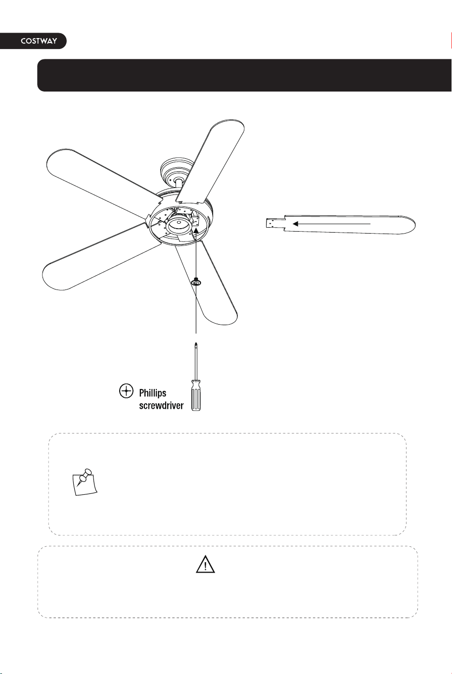
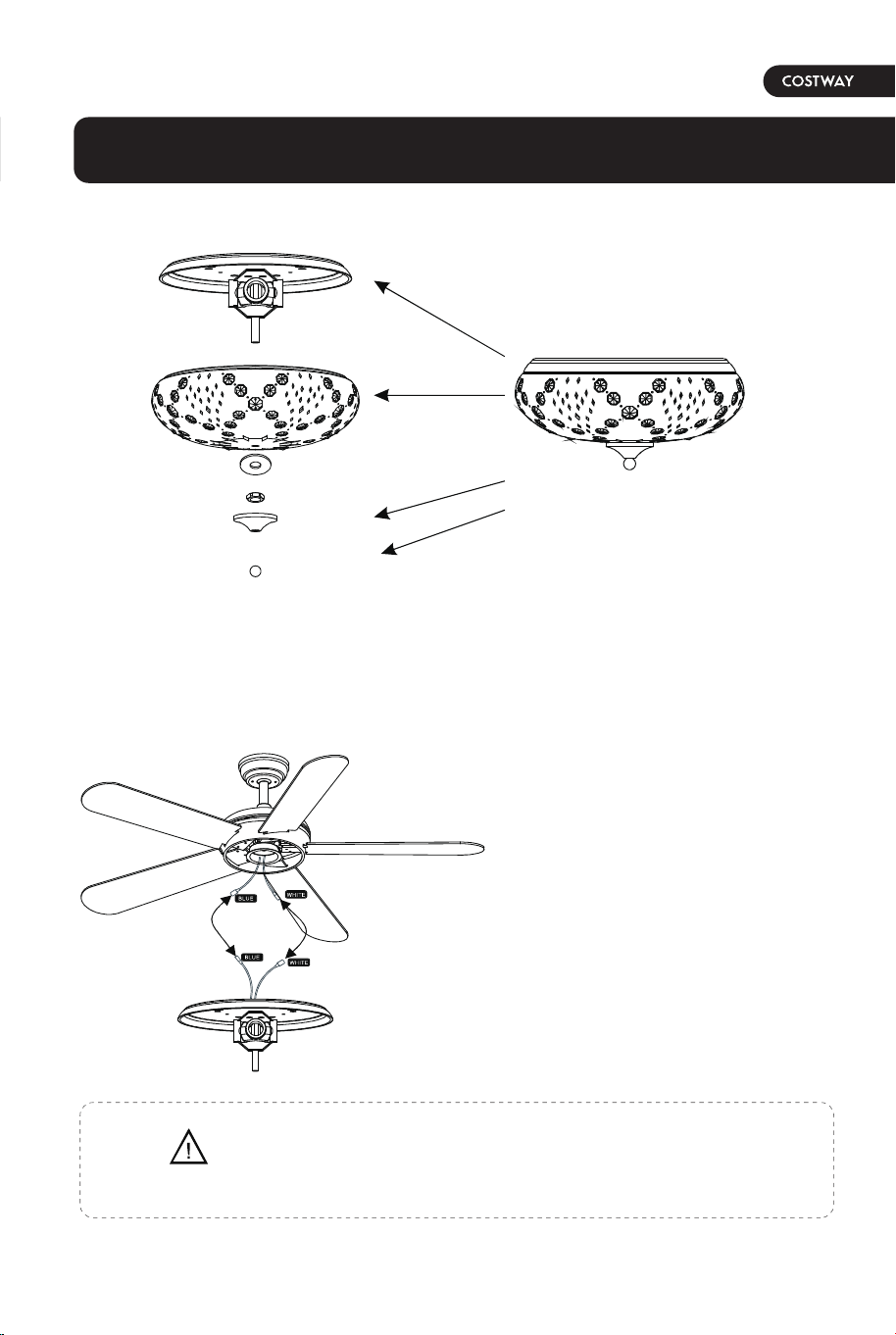
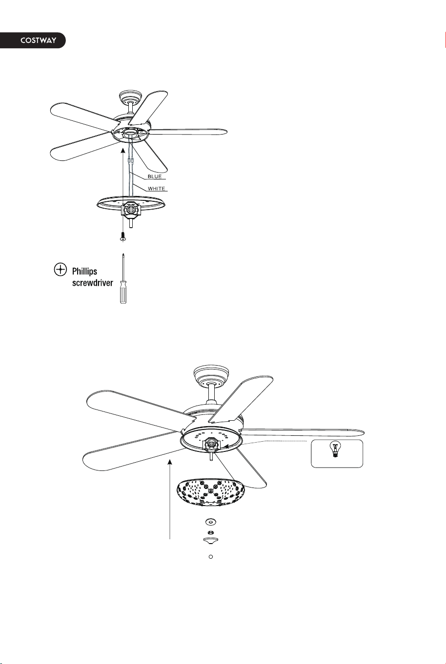
Assembly - Attaching the Fan Blades
1. Fastening the blade arms to the motor
1. Install the crystal shade & bulb
2. Connecting lamp wire
1. Fasten the arm to the fan-motor
assembly by inserting the alignment
post in the slot on the bottom of the
motor and tightening the preinstalled
arm screws.
2. Repeat this step for the remaining
blade assemblies.
1. Insert the "white" line in the
switching box of the motor into the
"white" line of the light and tie
insulated rubber tape.
2. Insert the "blue" line in the
switching box of the motor into the
"blue" line of the light and tie
insulated rubber tape.
Remove the rubber motor stops on the bottom of fan before installing the
blades or testing the motor.
WARNING
NOTE: Your fan features revolutionary advancements for
quick and easy blade installation. Including an alignment
post and captive blade arm screws.
Your fan blades are reversible. Select the blade side finish
which best accentuates your decor.
12 13
To reduce the risk of electric shock,disconnect the electrical
circuit to the fan before installing the light fixture.
CAUTION
Assembly - Attaching the Lights
1. After removing the bottom decoration of the lampshade,
get the parts and prepare for the next step of installation
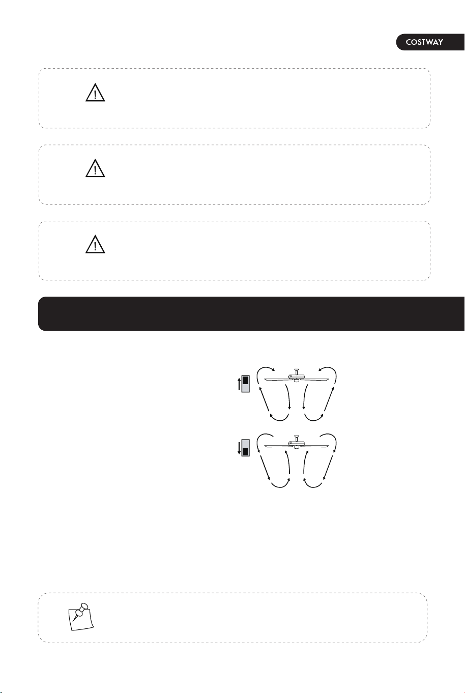
OPERATING YOUR FAN
3. Tighten the screw of the box cover.
4. Install the crystal shade & bulb
The appropriate speed settings for
warm or cool weather depends on
factors such as the room size, ceiling
height, and number of fans.
The slide switch (XX) controls the
direction of the blades: forward
(switch down) or reverse (switch
up).
1. Take the wire into the switching
box of the motor.
2. Align the opening of switching box
of the light at switch locking position
of the forward and reverse rotation of
the motors switching box. Place the
cover. Screw in the screw of the
switching box.
A. Warm weather-(Forward) A Downward airflow creates a cooling effect. This
allows you to set your air conditioner on a higher setting without affecting your
comfort.
B. Cool weather-(Reverse) An upward airflow moves warm air off the ceiling. This
allows you to set heating unit on a lower setting without affecting your comfort.
NOTE: Wait for the fan to stop before reversing the direction
of the blade rotation.
Make sure the power is off before attaching or
removing the shatter resistant bowl.
WARNING
Allow the shatter resistant bowl to cool completely before
rermoving.
CAUTION
Do not over tighten the hex nut,overtightening the
hex nut may cause the shatter resistant bowl to
break.
CAUTION
14 15
Operation
A.Warm Weather
(SUMMER TIME)
B.Cool Weather
(WINTER TIME)
ONLY USE E26 BULB
1. Select the appropriate bulb and install it on the lamp holder.
2. Instal the lampshade in the specified position.
Troubleshooting
• Check the main and branch circuit fuses or breakers.
• Check the line wire connections to the fan and switch wire
connections in the switch housing.
• Ensure all motor housing screws are snug.
• Ensure the screws that attach the fan blade bracket to the
motor hub are tight.
• Ensure the wire nut connections are not rattling against
each other or the interior wall of the switch housing.
• Allow a 24-hour "breaking in" period. Most noises
associated with a new fan disappear during this time.
• lf you are using the Ceiling Fan light kit, ensure the screws
securing the glassware are tight. Check that the light bulbs
are also secure.
• Ensure the canopy is a short distance from the ceiling. lt
should not touch the ceiling.
• Ensure your outlet box is secure and rubber isolator pads
were used between the mounting plate and outlet box.
• Check that all blades and bladearm screws are secure.
• Most fan wobble problems are caused when blade levels are
unequal.
• Check this level by selecting a point on the ceilin above the
tip of ine of the blades.
• Measure from a point on the center of each blade to the
point on the ceiling. Measure this distance.
• Rotate the fan until the next blade is positioned for
measurement.
• Repeat for each blade. Any measurement deviation should
be within 1/8 in.
• Run the fan for ten minutes. If the fan continues to wobble
please contact Customer Service.
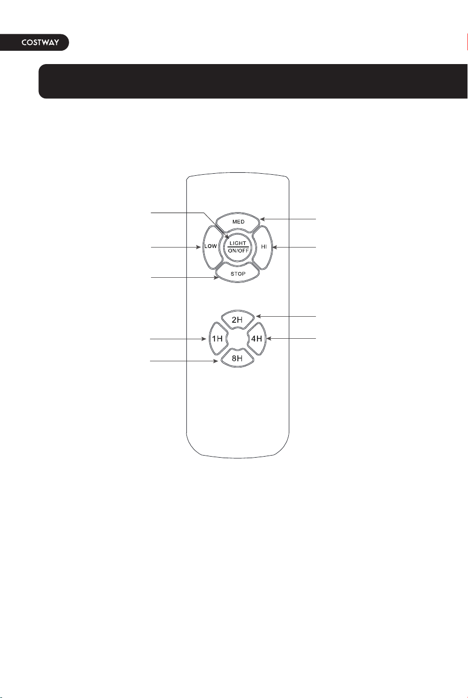
Use of remote control
Fan Speed Low Level
Fan STOP
Auto off after 1hr
Auto off after 8hr
Fan Speed Hight Level
Fan Speed Middle Level
LIGHT ON/OFF
Auto off after 4hr
Auto off after 2hr
Problem
The fan will
not start.
The fan
wobbles.
Solution
16 17
Troubleshooting
• Check the main and branch circuit fuses or breakers.
• Check the line wire connections to the fan and switch wire
connections in the switch housing.
• Ensure all motor housing screws are snug.
• Ensure the screws that attach the fan blade bracket to the
motor hub are tight.
• Ensure the wire nut connections are not rattling against
each other or the interior wall of the switch housing.
• Allow a 24-hour "breaking in" period. Most noises
associated with a new fan disappear during this time.
• lf you are using the Ceiling Fan light kit, ensure the screws
securing the glassware are tight. Check that the light bulbs
are also secure.
• Ensure the canopy is a short distance from the ceiling. lt
should not touch the ceiling.
• Ensure your outlet box is secure and rubber isolator pads
were used between the mounting plate and outlet box.
• Check that all blades and bladearm screws are secure.
• Most fan wobble problems are caused when blade levels are
unequal.
• Check this level by selecting a point on the ceilin above the
tip of ine of the blades.
• Measure from a point on the center of each blade to the
point on the ceiling. Measure this distance.
• Rotate the fan until the next blade is positioned for
measurement.
• Repeat for each blade. Any measurement deviation should
be within 1/8 in.
• Run the fan for ten minutes. If the fan continues to wobble
please contact Customer Service.
Use of remote control
Fan Speed Low Level
Fan STOP
Auto off after 1hr
Auto off after 8hr
Fan Speed Hight Level
Fan Speed Middle Level
LIGHT ON/OFF
Auto off after 4hr
Auto off after 2hr
Problem
The fan will
not start.
The fan
wobbles.
Solution
16 17
18
• Because of the fan's natural movement, some connections may become loose.
Check the support connections, brackets, and blade attachments twice a year.
Make sure they are secure. It is not necessary to remove the fan from the
ceiling.
• Clean your fan periodically to help maintain its new appearance over the
years. Do not use water when cleaning, as this could damage the motor or the
wood, or possibly cause an electric shock. Use only a soft brush or lint-free
cloth to avoid scratching the finish. The plathing is sealed with a lacquer to
minimize discoloration or tarnishing.
• You can apply a light coat of furniture polish to the wood for additional
protection and enhanced beauty. Cover small scratches with a light application
of shoe polish.
• You do not need to oil your fan. The motor has permanently-lubricated sealed
ball bearings.
Make sure the power is off before cleaning your fan.
WARNING
Care and Cleaning

THIS INSTRUCTION BOOKLET CONTAINS IMPORTANT SAFETY INFORMATION. PLEASE READ AND KEEP FOR FUTURE REFERENCE.
EN
DE
FR
ES
IT
PL
With your inspiring rating, COSTWAY will be more consistent to offer you EASY
SHOPPING EXPERIENCE, GOOD PRODUCTS and EFFICIENT SERVICE!
Mit Ihrer inspirierenden Bewertung wird COSTWAY konsistenter sein, um Ihnen EIN
SCHÖNES EINKAUFSERLEBNIS, GUTE PRODUKTE und EFFIZIENTEN SERVICE zu
bieten!
Avec votre évaluation inspirante, COSTWAY continuera à fournir une EXPÉRIENCE
D’ACHAT PRATIQUE, des PRODUITS DE QUALITÉ et un SERVICE EFFICACE !
Con su calificación inspiradora, COSTWAY será más consistente para ofrecerle
EXPERIENCIA DE COMPRA FÁCIL, BUENOS PRODUCTOS y SERVICIO EFICIENTE.
Con la tua valutazione incoraggiante, COSTWAY sarà più coerente per offrirti ESPE-
RIENZA DI ACQUISTO FACILE, BUONI PRODOTTI e SERVIZIO EFFICIENTE!
Dzięki twojej opinii COSTWAY będzie mógł oferować jeszcze WYGODNIEJSZE
ZAKUPY, LEPSZE PRODUKTY i SPRAWNIEJSZĄ OBSŁUGĘ KLIENTA.
US office: Fontana UK office: Ipswich AU office: Truganina
DE office: Hamburg
FR office: Saint Vigor d'Ymonville
PL office: Gdańsk
52" CEILING FAN
ES10100US
USER’S MANUAL