Loading ...
Loading ...
Loading ...
C
C
A
7
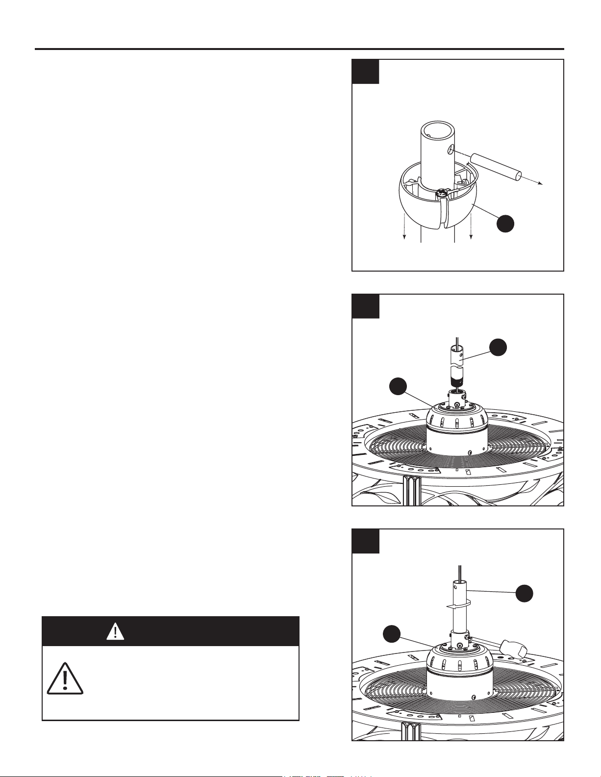
ASSEMBLY INSTRUCTIONS
1. Remove the hanger ball portion from the
downrod/hanger ball assembly (C) by loosen-
ing the set screw in the hanger ball until the
ball falls freely down the downrod. Remove the
pin from the downrod, then remove the hanger
ball. Retain the pin and hanger ball for
reinstallation in Step 5. (Fig. 1)
1
2
3
C
A
2. Loosen the two set screws in the downrod
support of the motor assembly (A). Route the
black, white and blue wires through the
downrod of the downrod/hanger ball assembly
(C). (Fig. 2)
3. Thread the downrod of the downrod/hanger
ball assembly (C) into the downrod support
on top of the motor assembly (A). Install the
clevis pin from the downrod/hanger ball
assembly (C) by aligning the holes in the
downrod support of the motor assembly (A)
with the holes in the downrod of the
downrod/hanger ball assembly (C). Secure
clevis pin with hairpin clip from the
downrod/hanger ball assembly (C). Tighten
the two set screws in the downrod support of
the motor assembly (A). (Fig. 3)
WARNING
It is critical that the clevis pin in the
downrod support is properly installed and
the set screws is securely tightened.
Failure to do so could result in the fan
falling.
Loading ...
Loading ...
Loading ...