Loading ...
Loading ...
Loading ...
11
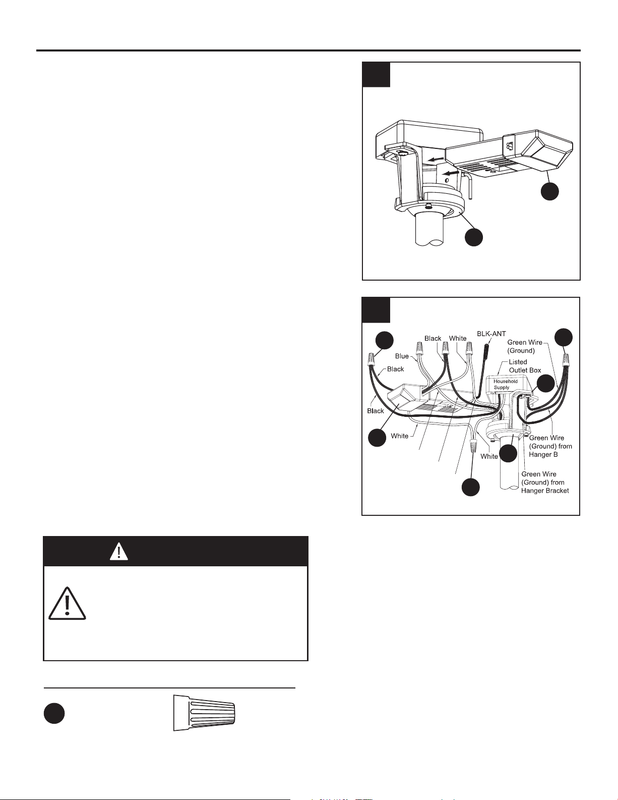
WIRING INSTRUCTIONS (Continued)
3. Slide the receiver unit (G) into the open end of
the hanger bracket (B). (Fig. 3)
G
B
3
G
B
C
AA
AA
AA
4
Blue to Light
Black to Motor
White to Motor
all
4. Connect green wires from hanger bracket (B)
and downrod/hanger ball assembly (C) to bare
(ground) wire using wire connector (AA).
Connect black wire from receiver unit (G)
marked “AC IN L” to black supply wire using wire
connector (AA).Connect white wire from
receiver unit (G) marked “AC IN N” to white
supply wire using wire connector (AA). Connect
white wire from receiver unit (G) marked “TO
MOTOR N” to white wire from fan using wire
connector supplied with receiver unit (G).
Connect black wire from receiver unit marked
“TO MOTOR L” to black wire from fan using wire
connector. Lastly, connect blue wire from
receiver unit (G) to the blue fan light
wire using
wire connector. (Fig. 4)
WARNING
Check to see that all connections are
tight, including ground, and that no bare
wire is visible at the wire connectors
except for the ground wire. Do not
operate fan until the blades are in place.
Noise and motor damage could result.
Hardware Used
AA
x 3
Wire
Connectors
Loading ...
Loading ...
Loading ...