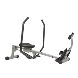
ROWING MACHINE
WITH BLUETOOTH
SF-RW521020
USER MANUAL
English, Page 1~12 IMPORTANT! Please retain owner’s manual for maintenance and adjustment instructions. Your satisfaction
is very important to us, PLEASE DO NOT RETURN UNTIL YOU HAVE CONTACTED US:
[email protected] or 1-877-90SUNNY (877-907-8669).
Español, Page 13~24 ¡IMPORTANTE! Conserve el manual del propietario para las instrucciones de mantenimiento y ajuste. Su
satisfacción es muy importante para nosotros, NO DEVUELVA HASTA HABERNOS ONTACTADO:
[email protected] ó 1-877-90SUNNY (877-907-8669).
Français, Page 25~36 IMPORTANT! Veuillez conserver le manuel du propriétaire pour les instructions de réglage et d’entretien.
Votre satisfaction est très importante pour nous, VEUILLEZ NE PAS EFFECTUER DE RETOUR AVANT
DE NOUS AVOIR CONTACTÉ: [email protected] ou 1-877-90SUNNY (877-907-8669).
Deutsche, Seite 37~48 WICHTIG! Bitte bewahren Sie das Benutzerhandbuch für Wartungs- und Einstellanweisungen auf. Ihre
Zufriedenheit ist besonders wichtig für uns, BITTE SCHICKEN SIE DAS PRODUKT NICHT ZURÜCK,
oder 1-877-90SUNNY (877-907-8669).
Italiano, Pagina 49~60 IMPORTANTE! Conservare il manuale utente per le istruzioni di manutenzione e regolazione. La vostra
soddisfazione è molto importante per noi, VI PREGHIAMO DI NON EFFETTUARE RESI SENZA AVERCI
PRIMA CONTATTATO: [email protected] o 1- 877 - 90SUNNY (877-907-8669).

1
IMPORTANT SAFETY INFORMATION
We thank you for choosing our product. To ensure your safety and health, please use this
equipment correctly. It is important to read this entire manual before assembling and using the
equipment. Safe and effective use can only be achieved if the equipment is assembled, maintained,
and used properly. It is your responsibility to ensure that all users of the equipment are informed of
all warnings and precautions.
1. Before starting any exercise program, you should consult your physician to determine if you
have any medical or physical conditions that could put your health and safety at risk or prevent
you from using the equipment properly. Your physician’s advice is essential if you are taking
medication that affects your heart rate, blood pressure, or cholesterol level.
2. Be aware of your body’s signals. Incorrect or excessive exercise can damage your health. Stop
exercising if you experience any of the following symptoms: pain, tightness in your chest,
irregular heartbeat, shortness of breath, lightheadedness, dizziness, or feelings of nausea. If
you do experience any of these conditions, you should consult your physician before continuing
with your exercise program.
3. Keep children and pets away from the equipment. The equipment is designed for adult use
only.
4. Use the equipment on a solid, flat level surface with a protective cover for your floor or carpet.
To ensure safety, the equipment should have at least 2 feet (60 CM) of free space all around it.
5. Ensure that all nuts and bolts are securely tightened before using the equipment. The safety of
the equipment can only be maintained if it is regularly examined for damage and/or wear and
tear.
6. Always use the equipment as indicated. If you find any defective components while assembling
or checking the equipment, or if you hear any unusual noises coming from the equipment
during exercise, discontinue use of the equipment immediately and do not use until the problem
has been rectified.
7. Wear suitable clothing while using the equipment. Avoid wearing loose clothing that may
become entangled in the equipment.
8. Do not place fingers or objects into the moving parts of the equipment.
9. The maximum weight capacity of this unit is 285 lbs (130 kgs).
10. This equipment is not suitable for therapeutic use.
11. To avoid bodily injury and/or damage to the product or property, proper lifting and moving are
required.
12. Your product is intended for use in cool and dry conditions. You should avoid storage in
extreme cold, hot or damp areas as this may lead to corrosion and other related problems.
13. This equipment is designed for indoor and home use only; it is not intended for commercial
use.
2
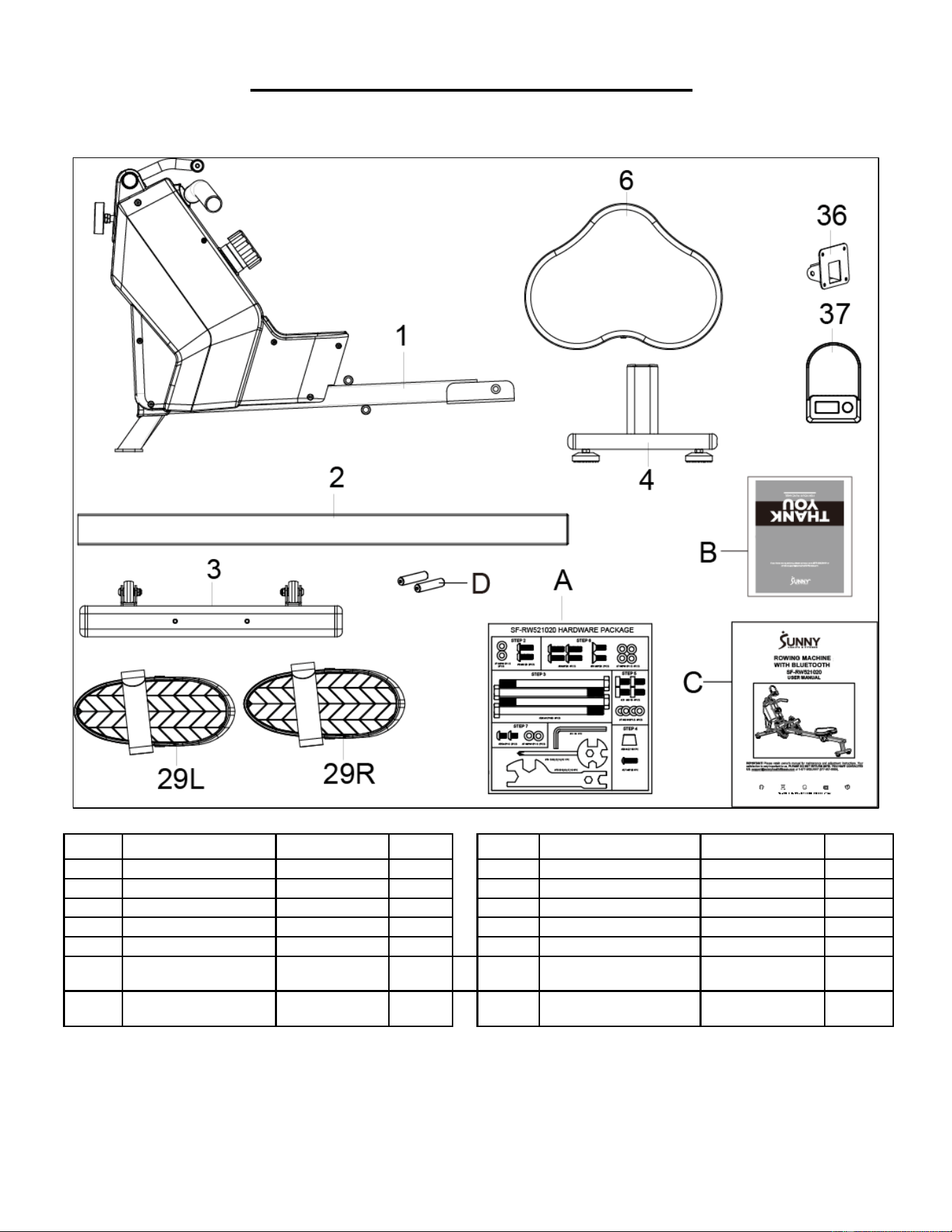
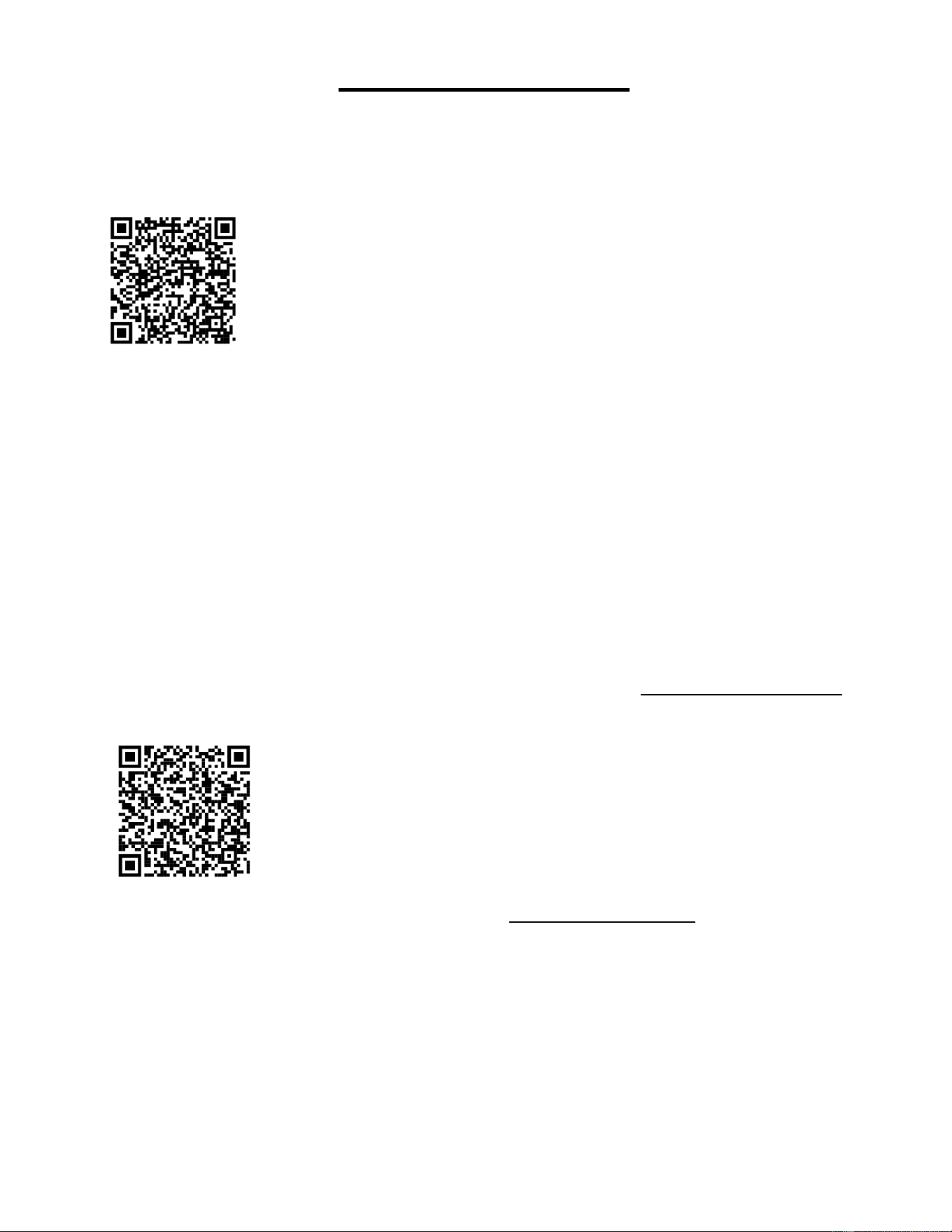
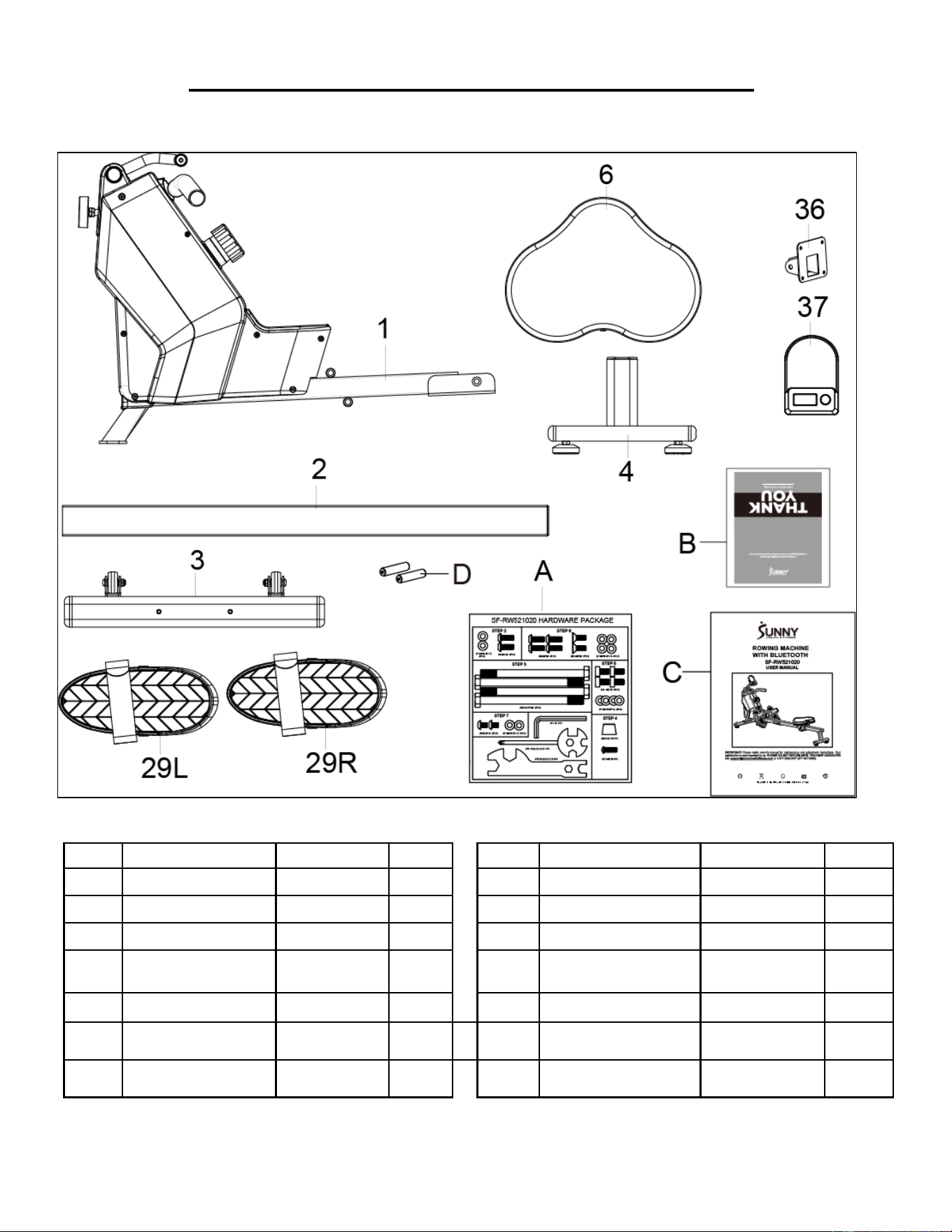
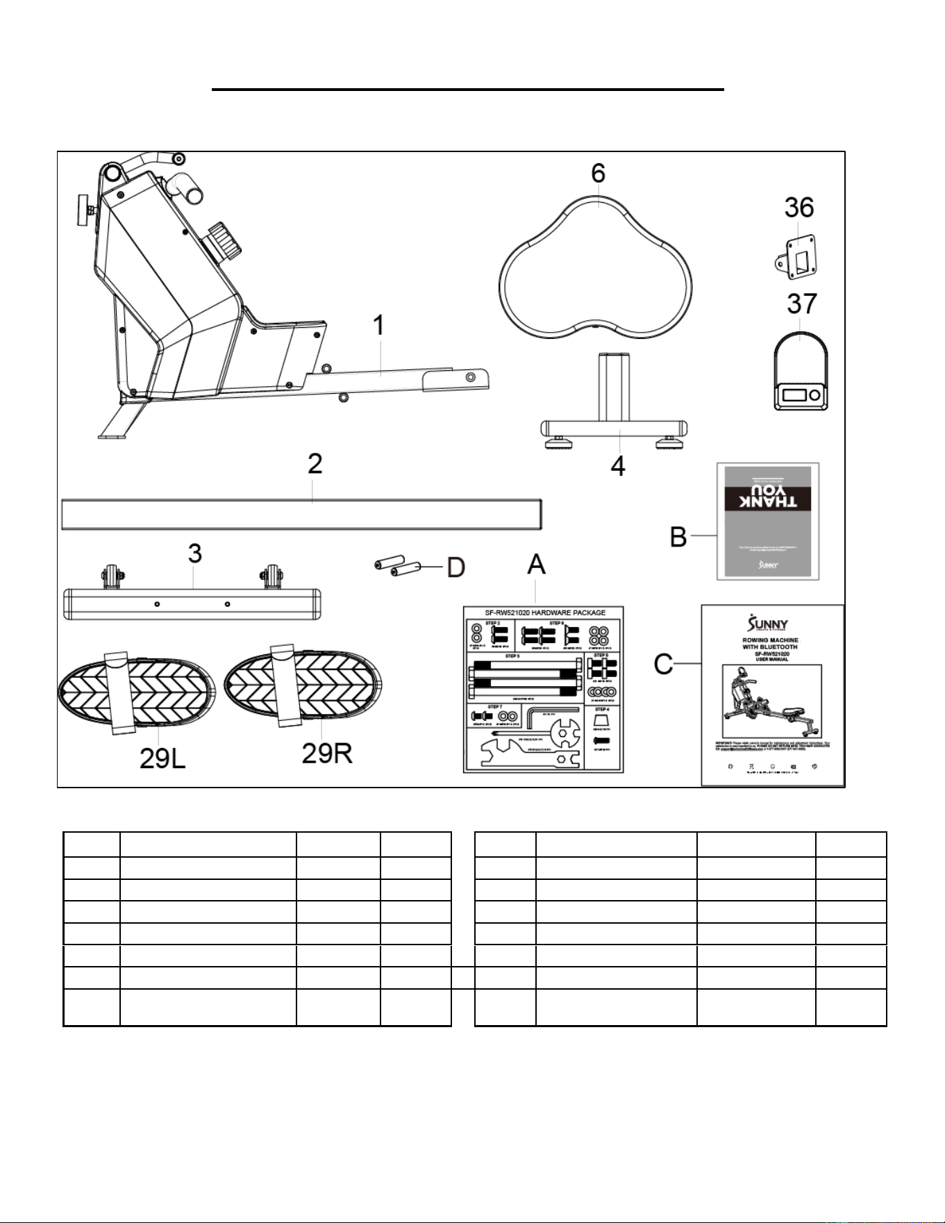
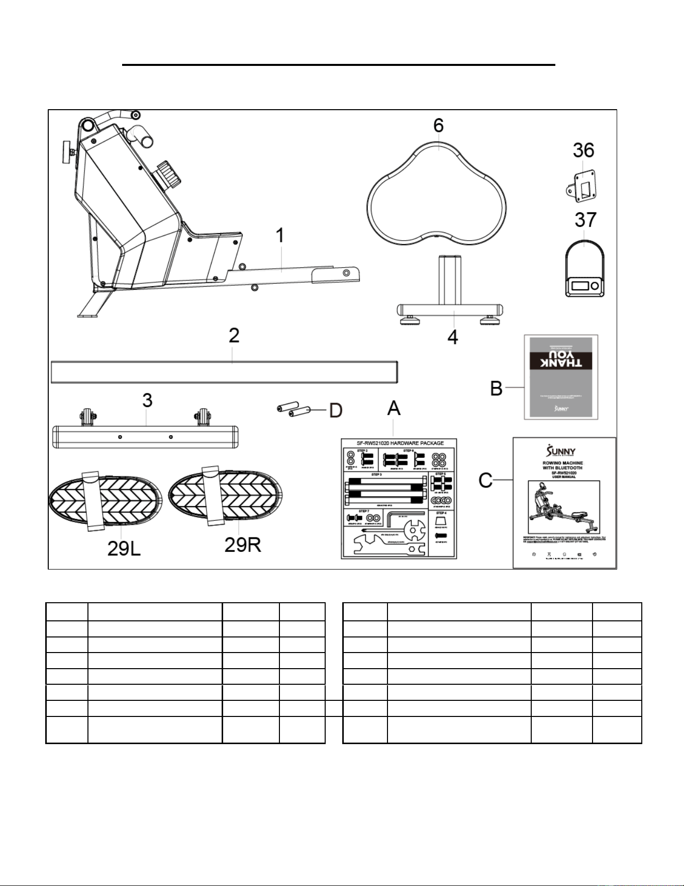
PRE-ASSEMBLY CHECK LIST
Before you start to assemble, please make sure all parts are included:
No.
Description
Spec.
Qty.
No.
Description
Spec.
Qty.
1
Main Frame
1
29L
Left Pedal
1
2
Sliding Rail
1
29R
Right Pedal
1
3
Front Stabilizer
1
A
Hardware Package
1
4
Rear Stabilizer
1
B
Thank You Card
1
6
Seat
1
C
Manual
1
36
Computer Support
1
D
AAA Battery
2
37
Computer
1
3
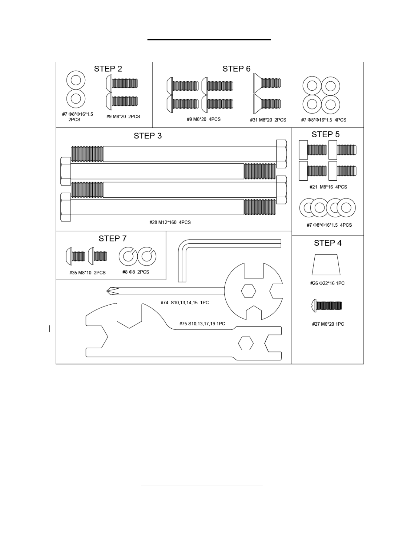
HARDWARE PACKAGE
Ordering Replacement Parts (U.S. and Canadian Customers only)
Please provide the following information in order for us to accurately identify the part(s) needed:
✓ The model number (found on cover of manual).
✓ The product name (found on cover of manual).
✓ The part number found on the “EXPLODED DIAGRAM” (pages 61-62) and “PARTS LIST” (page
12).
Please contact us at [email protected] or 1-877-90SUNNY (877-907-8669)
4
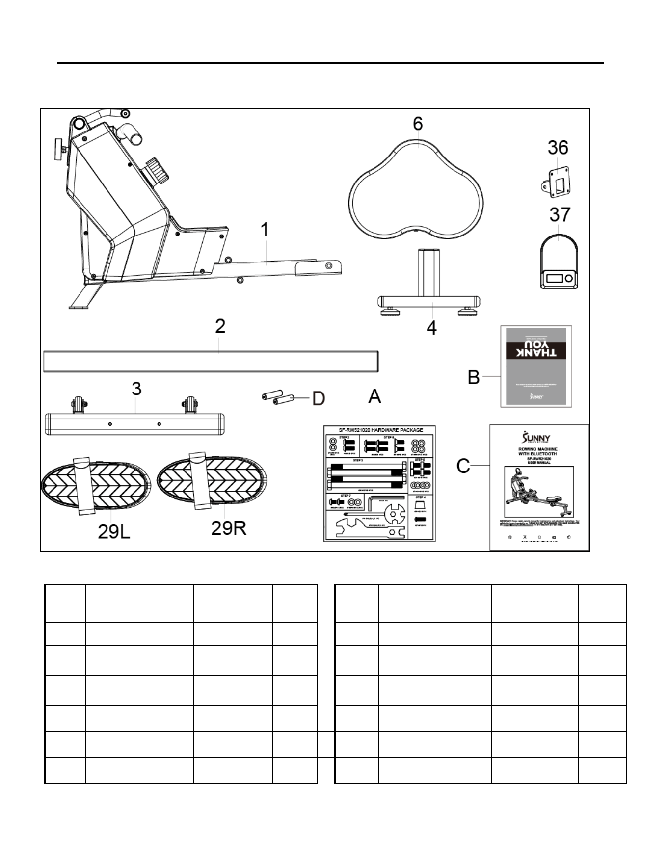
ASSEMBLY INSTRUCTIONS
We value your experience using Sunny Health and Fitness products. For assistance with parts or
troubleshooting, please contact us at suppo[email protected] 1-877-90SUNNY (877-907-
8669).
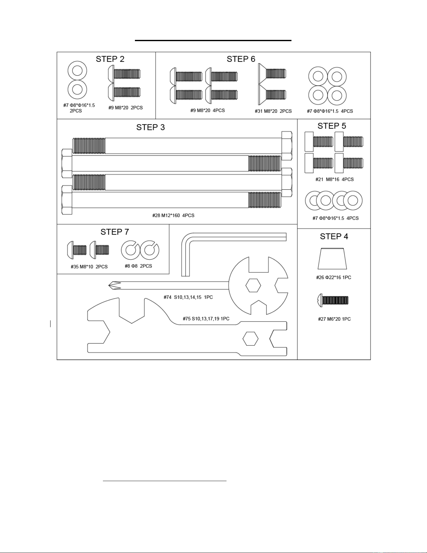
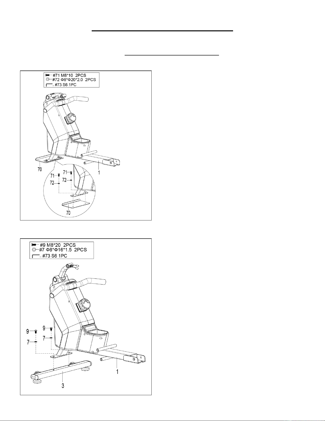
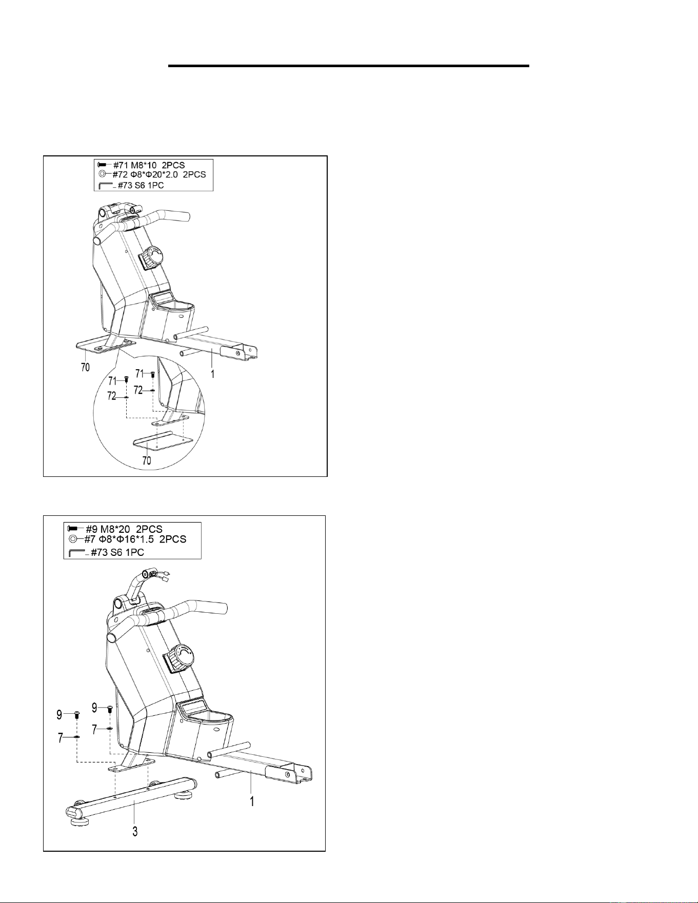
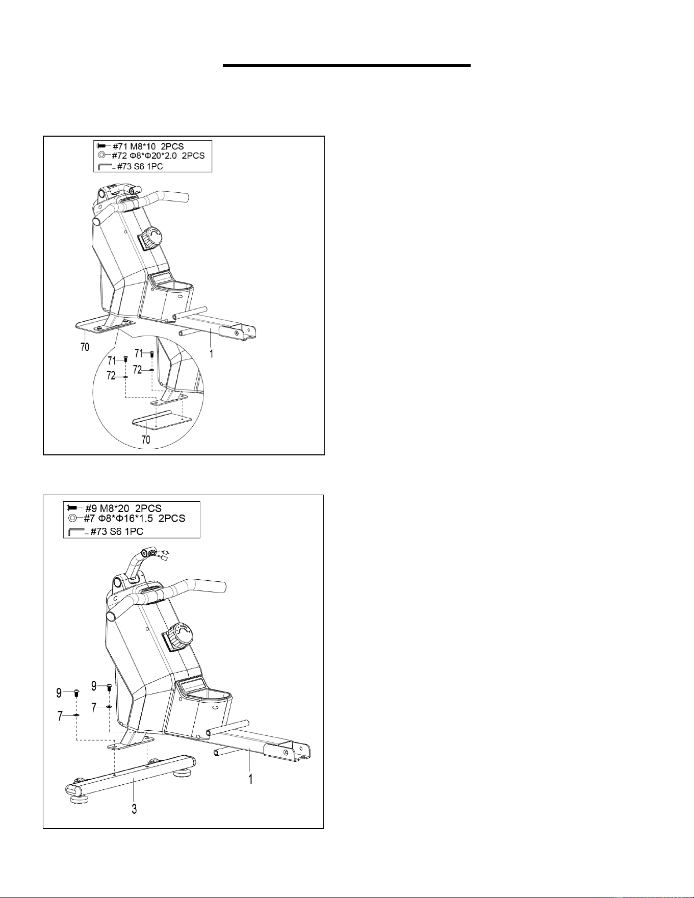
STEP 2:
Attach Front Stabilizer (No. 3) to Main Frame
(No. 1) using 2 Bolts (No. 9) and 2 Washers
(No. 7). Tighten and secure with Allen
Wrench (No. 73).
STEP 1:
Unscrew 2 Screws (No. 71), 2 Plastic Washers
(No. 72) and 1 Shipping Board (No. 70) from
Main Frame (No. 1) with Allen Wrench (No.
73).
You may save these parts Screws (No. 71),
Plastic Washers (No. 72), Shipping Board
(No. 70) in case you would like to repackage
and transport this equipment in the future.
5
We value your experience using Sunny Health and Fitness products. For assistance with parts or
troubleshooting, please contact us at suppo[email protected] 1-877-90SUNNY (877-907-
8669).
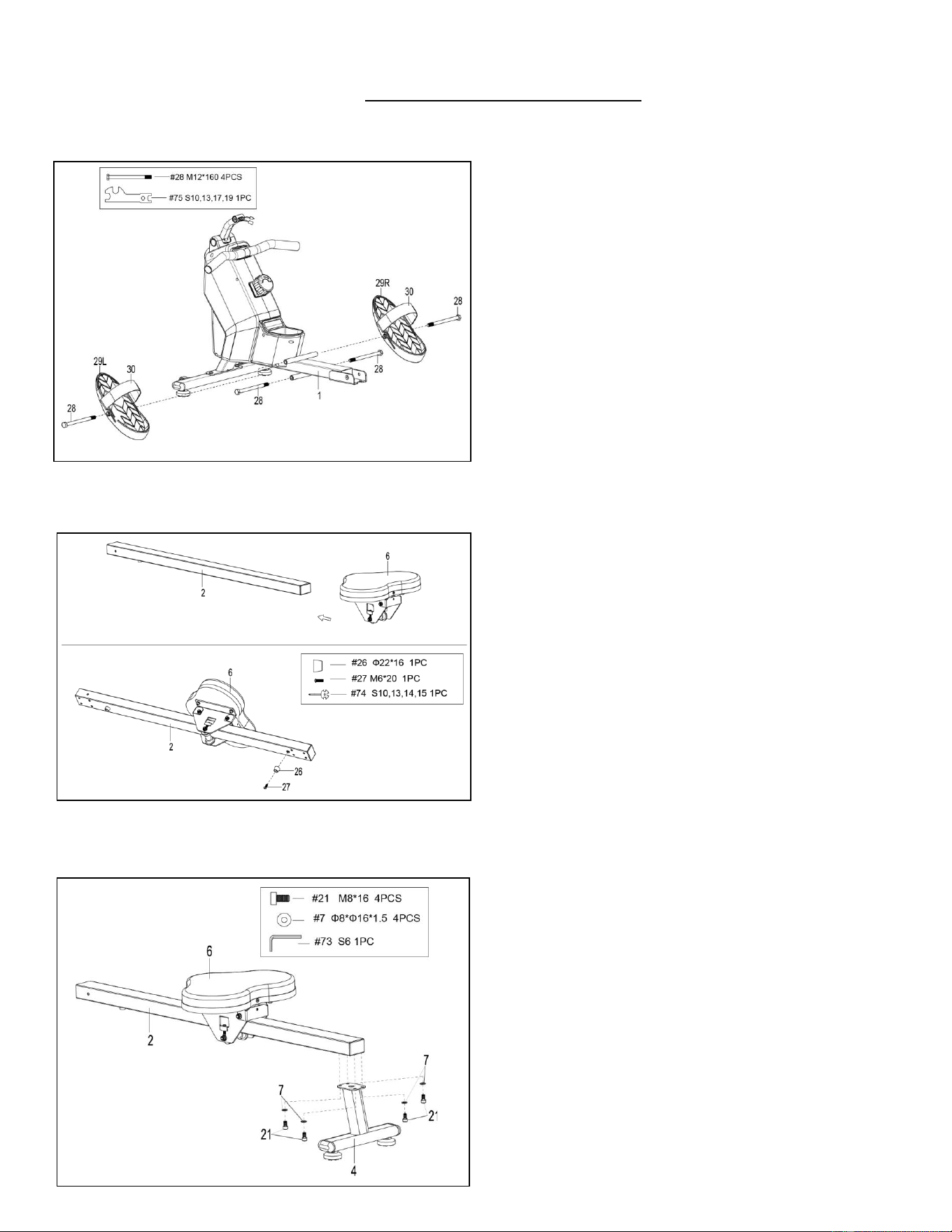
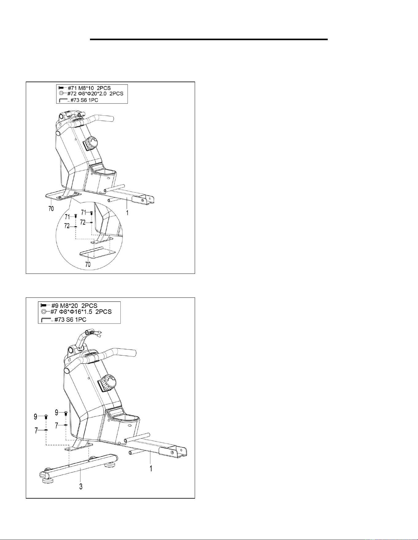
STEP 3:
Attach 2 Bolts (No. 28) into the bottom hole in
position B of Main Frame (No. 1), with
Spanner (No. 75).
Insert 2 Bolts (No. 28) into the upper hole in
position A of the Main Frame (No. 1) through
the 2 Pedals (No. 29L/R). Tighten with
Spanner (No. 75).
NOTE: The 2 Pedals (No. 29L/R) should rest
on Bolts (No. 28) that are in position B.
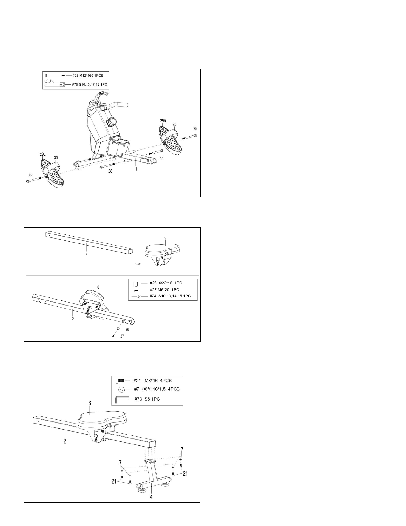
STEP 4:
Slide the Seat (No. 6) into the Sliding Rail
(No. 2).
Attach 1 Limit Mat (No. 26) onto the Sliding
Rail (No. 2) using 1 Screw (No. 27), then
tighten with Spanner (No. 74).
STEP 5:
Attach the Rear Stabilizer (No. 4) to the
Sliding Rail (No. 2) using 4 Bolts (No. 21) and
4 Washers (No. 7). Tighten and secure with
Allen Wrench (No. 73).
6
We value your experience using Sunny Health and Fitness products. For assistance with parts or
troubleshooting, please contact us at suppo[email protected] 1-877-90SUNNY (877-907-
8669).
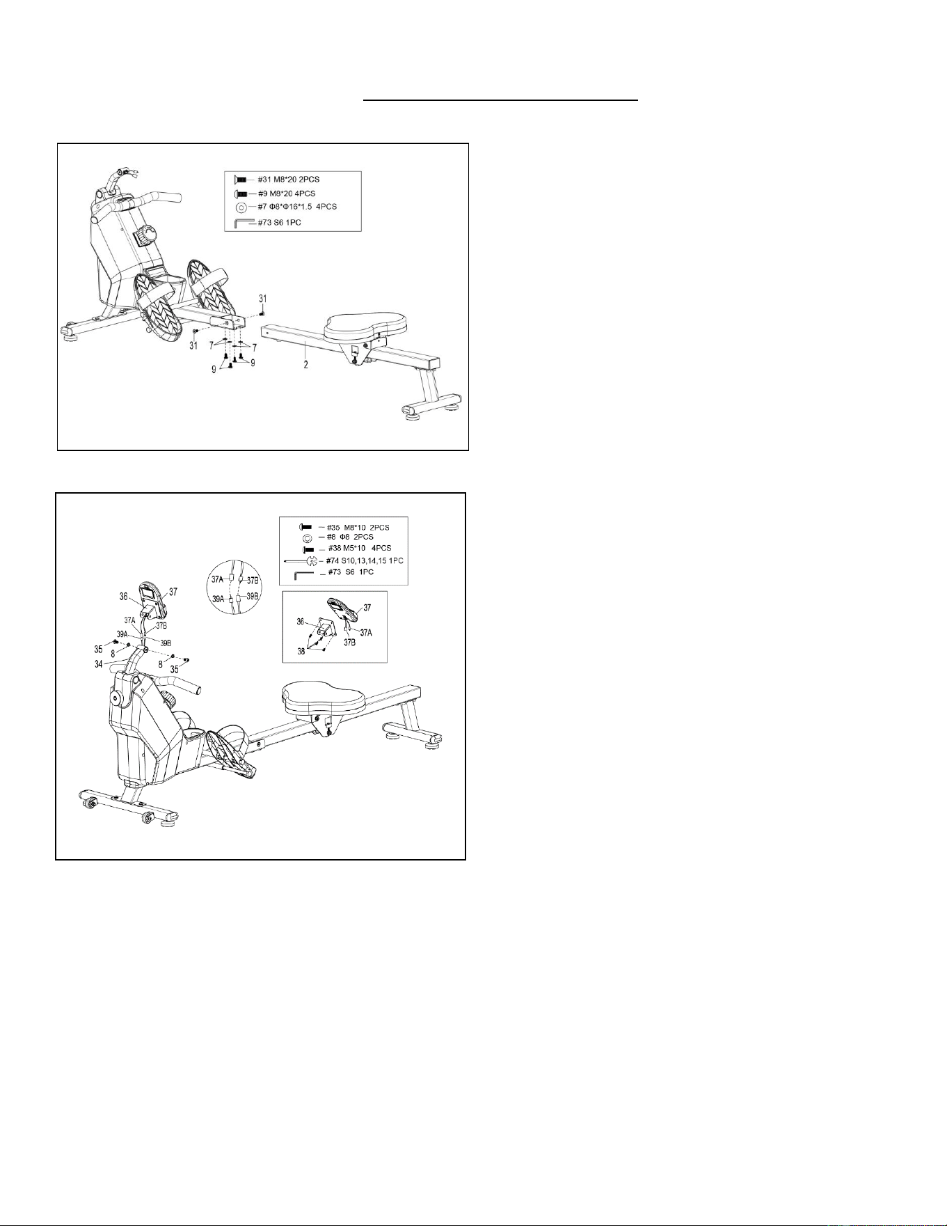
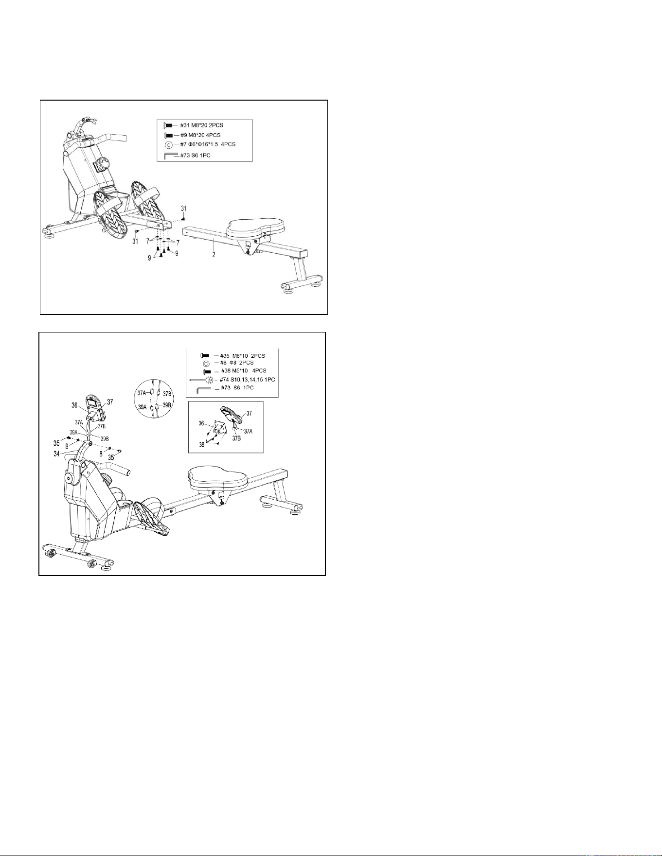
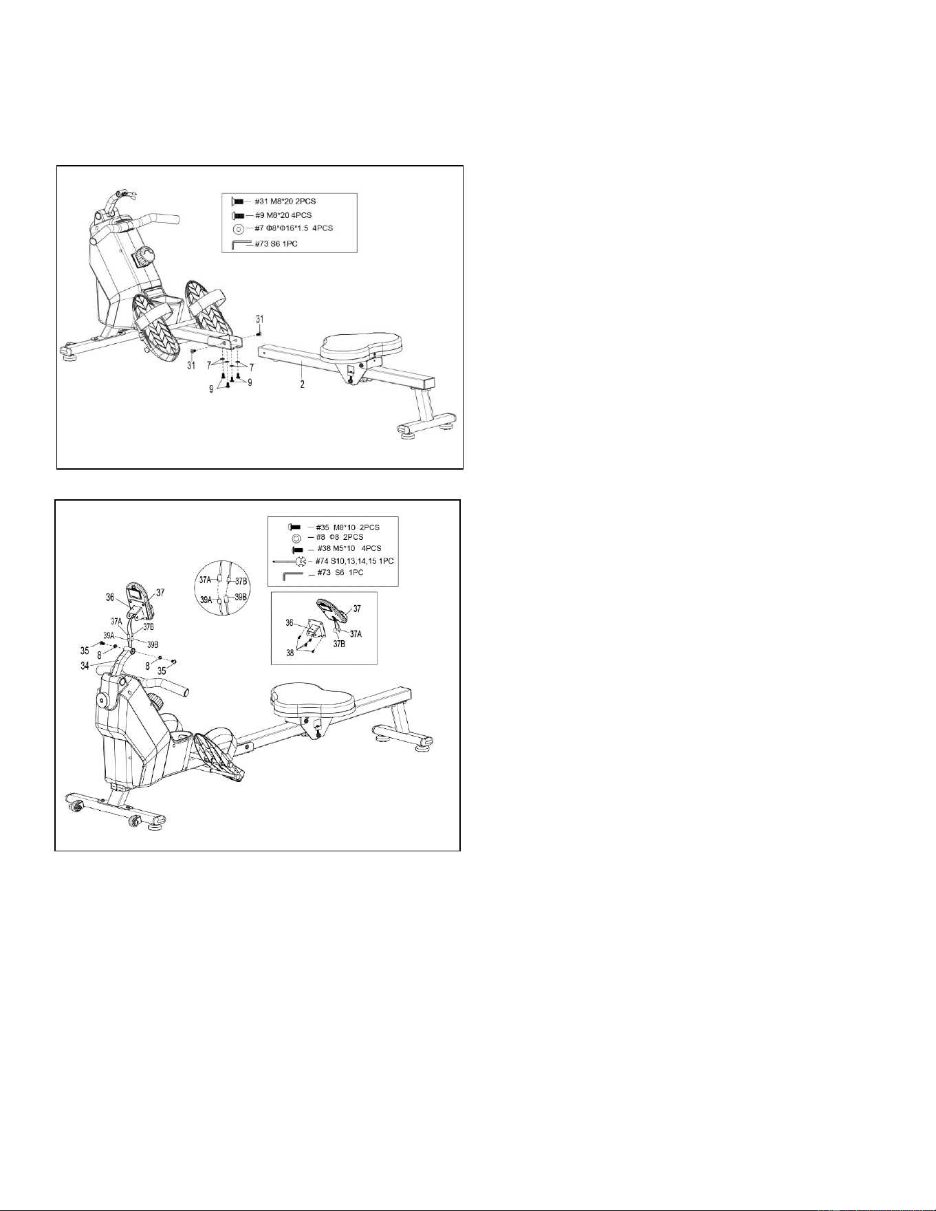
STEP 6:
Attach the Sliding Rail (No. 2) to the Main
Frame (No. 1) by securing 2 Bolts (No. 31)
onto the left and right sides of the Main Frame
(No. 1). Don’t tighten the Bolts (No. 31) now.
Secure 4 Bolts (No. 9) and 4 Washers (No. 7)
to the bottom of the Main Frame (No. 1).
Tighten all the 4 Bolts (No. 9) and 2 Bolts
(No. 31) with Allen Wrench (No. 73) now.
STEP 7:
Remove 4 Bolts (No. 38) from the back of the
Computer (No. 37) with the Spanner (No.
74).
First insert Computer Wires A/B (No. 37A/B)
through Computer Support (No. 36), then
attach the Computer (No. 37) to the
Computer Support (No. 36) using 4 Bolts
(No. 38) that were removed. Tighten and
secure with Spanner (No. 74).
Connect the Sensor Wire A (No. 39A) to the
Computer Wire A (No. 37A) and connect the
Sensor Wire B (No. 39B) to the Computer
Wire B (No. 37B). Next, Insert the connected
wire into Computer Supporting Tube (No.
34).
Attach the Computer Support (No. 36) to
Computer Supporting Tube (No. 34) using 2
Bolts (No. 35) and 2 Spring Washers (No. 8).
Tighten and secure with Allen Wrench (No.
73) and Spanner (No. 74).
The assembly is complete!
7
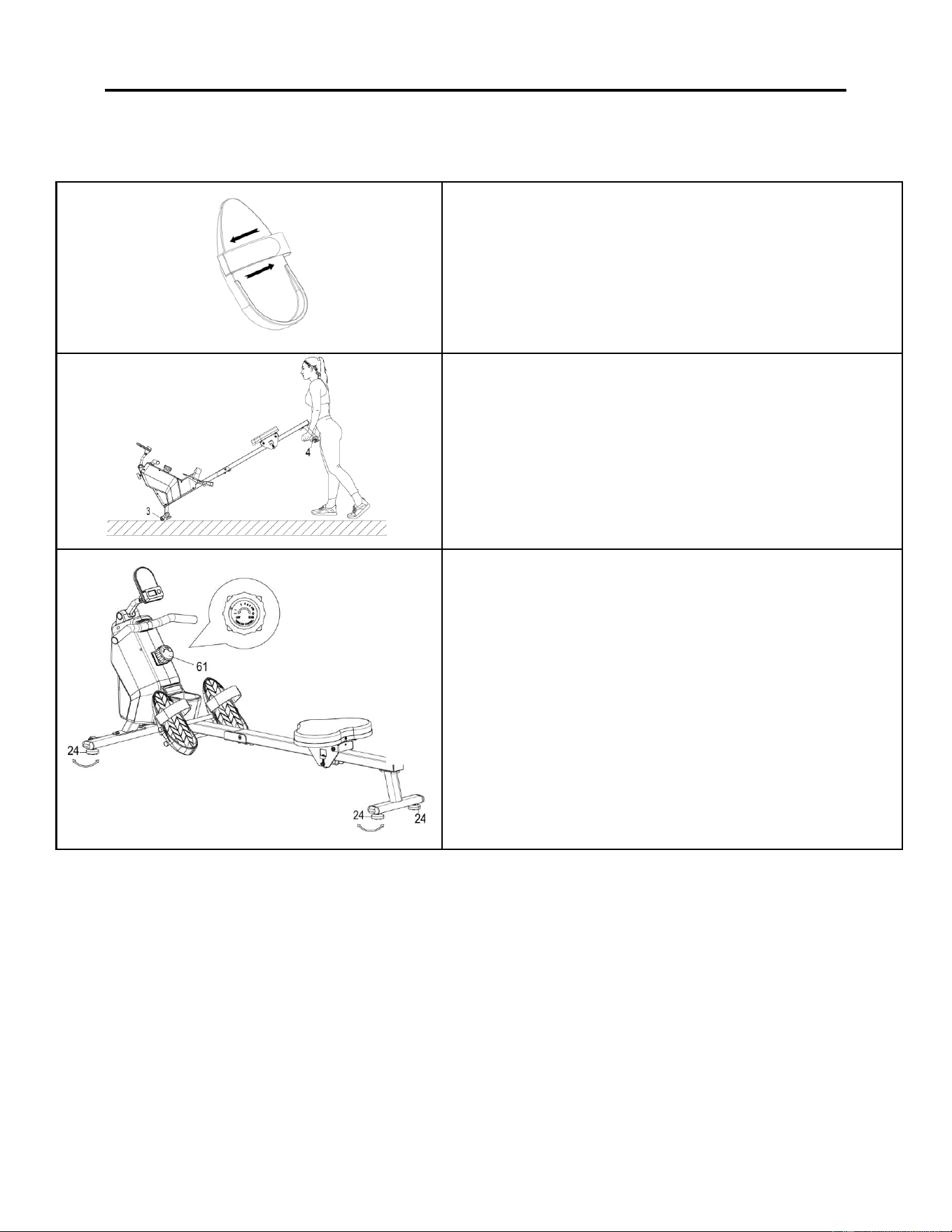
ADJUSTMENTS & USAGE GUIDE
CAUTION! Moving parts, such as the seat, can cut and crush. Keep hands clear of the sliding rail
during use!
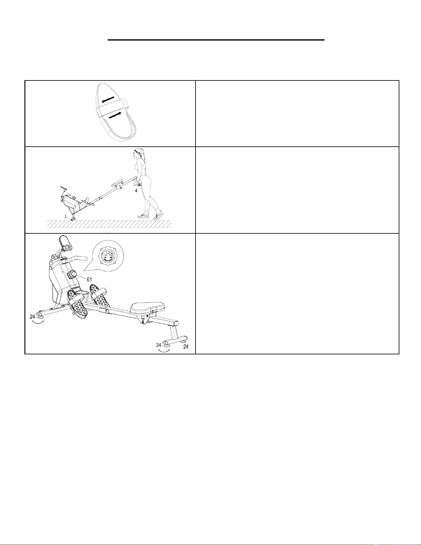
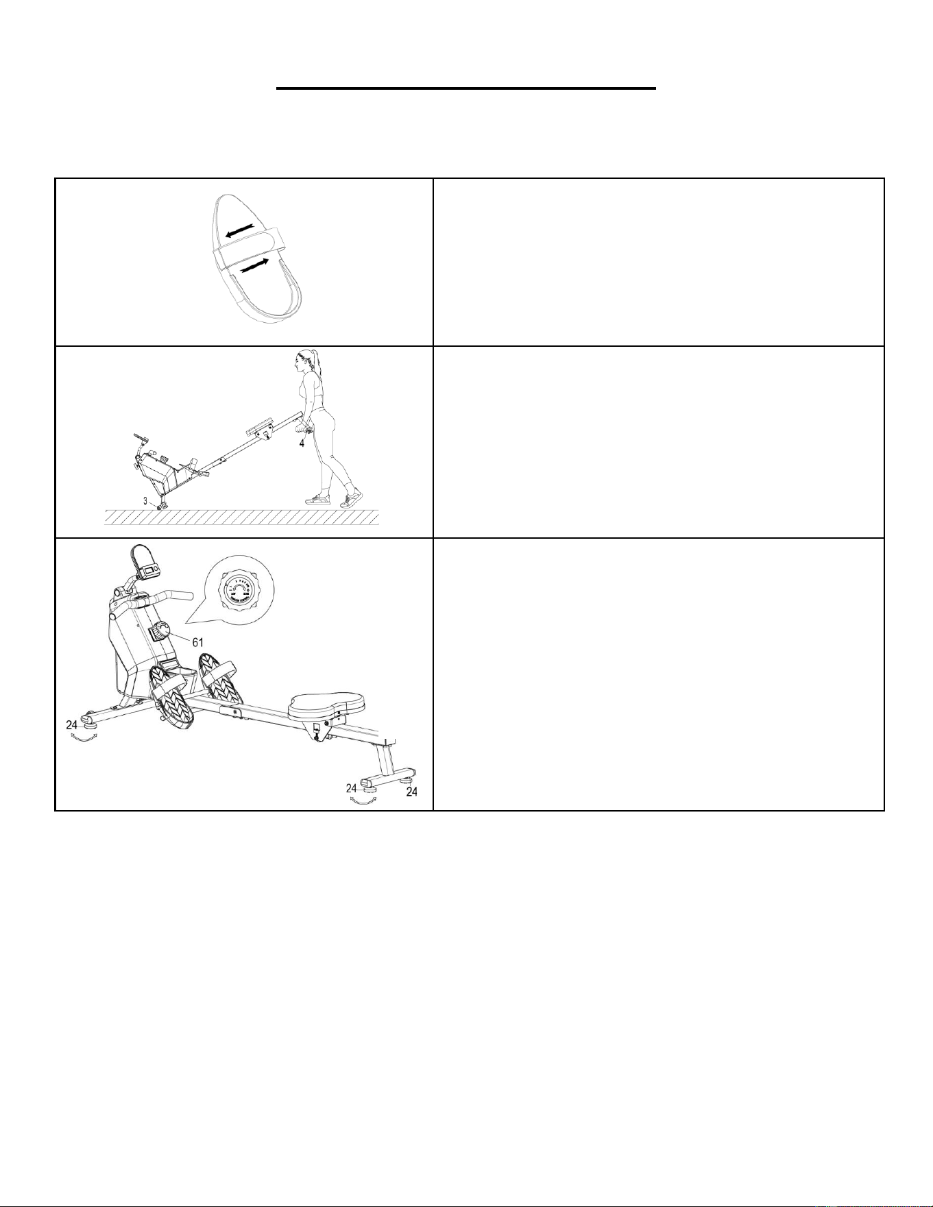
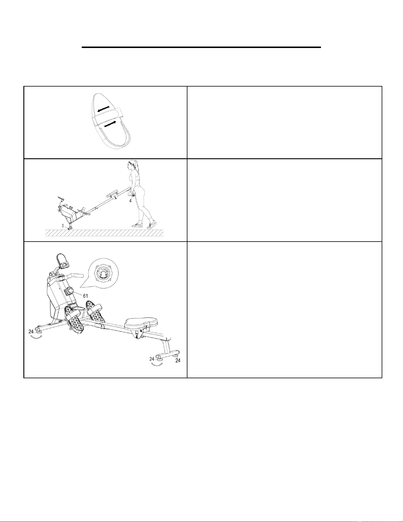
PEDAL STRAP ADJUSTMENT
The pedal straps are adjustable and can be
personalized to fit the user’s foot size.
NOTE: To avoid injury, please adjust the pedal straps
to user’s foot before exercise.
MOVING THE ROWER
To move the rower, lift up the Rear Stabilizer (No. 4)
until the transportation wheels on the Front
Stabilizer (No. 3) touch the ground with the
transportation wheels on the ground, you can
transport the rower to the desired location with ease.
ADJUSTING THE BALANCE AND RESISTANCE
Adjust the Foot Pads (No. 24) on the rear support of
the rower if the rower is unbalanced during use.
Rotate the Tension Control Knob (No. 61)
clockwise to increase the level of resistance. Rotate
the Tension Control Knob (No. 61) counter-
clockwise to decrease the level of resistance.
Tension levels are set at Level 1 being the lowest and
Level 8 being the highest.
8
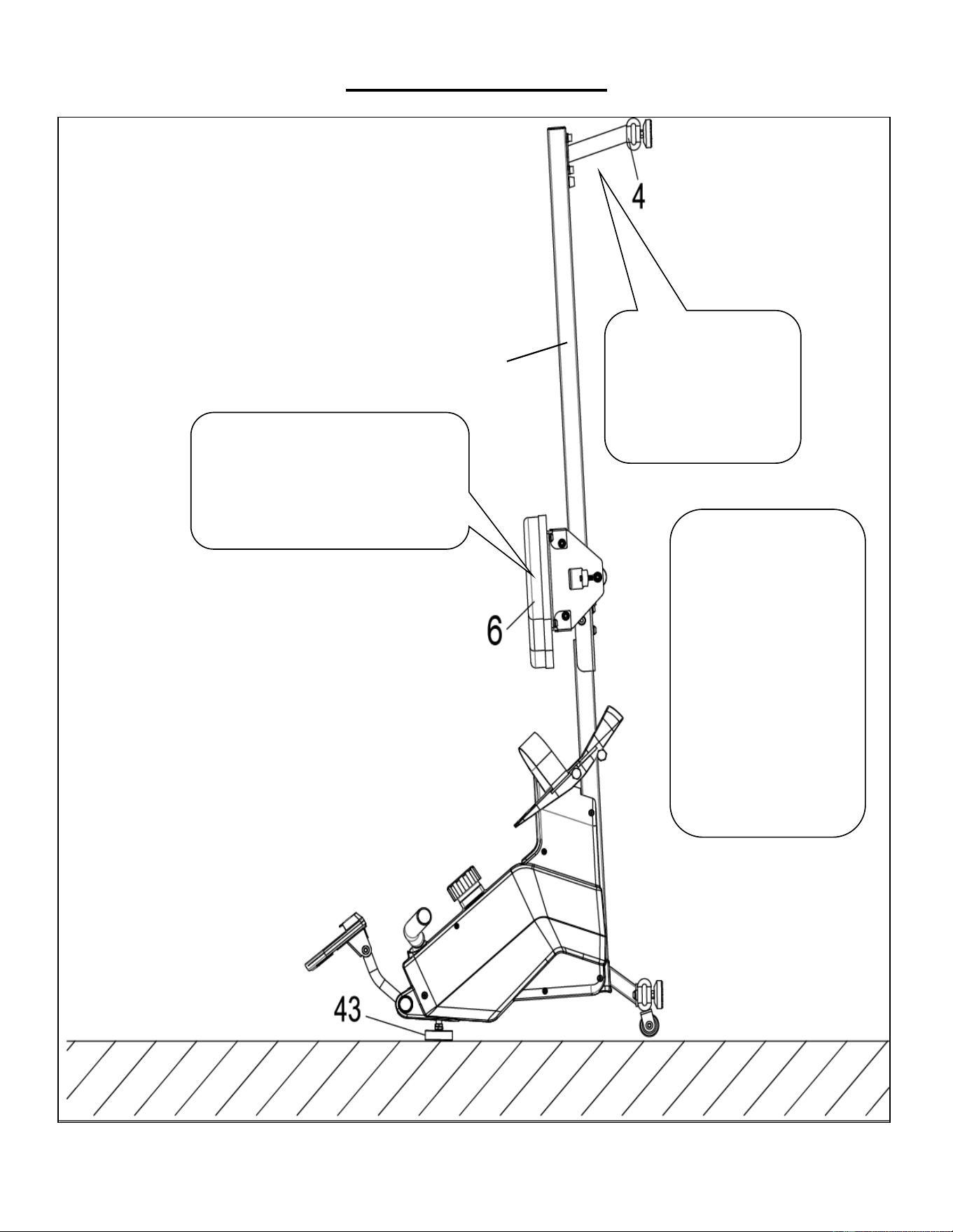
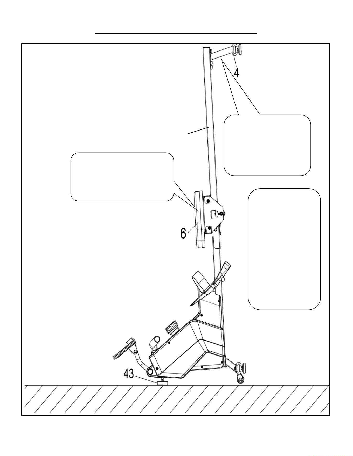
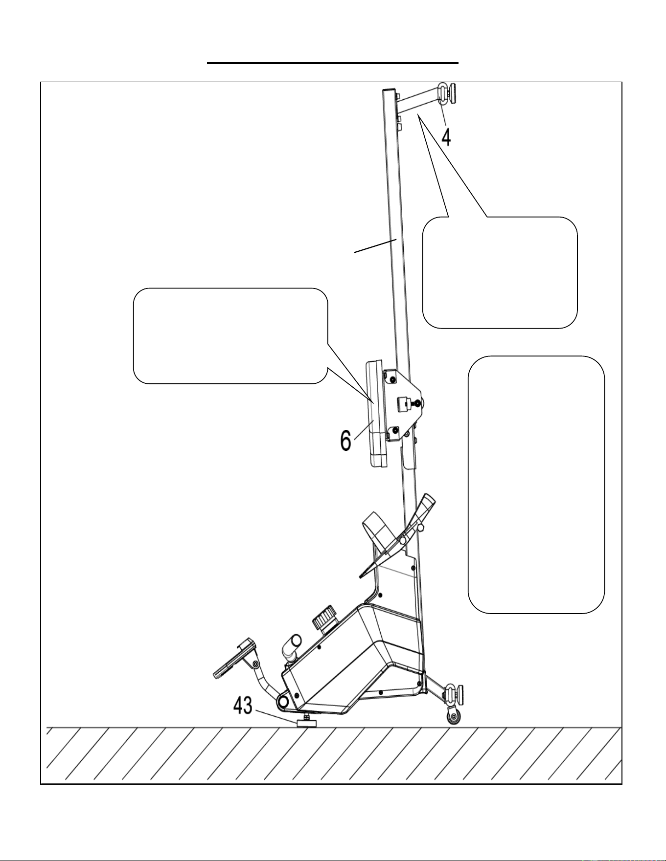
STORAGE GUIDE
CAUTION!
Use caution when you
vertically place the
Sliding Rail (No. 2) as
your head may touch the
Rear Stabilizer (No. 4).
When not in use, you
can save space by
placing the rower upright
on the floor with Foot
Pad (No. 43).
SAFETY
NOTE: The Seat (No. 6)
will glide down when
placing the Sliding Rail
(No. 2) in an upright
position.
CAUTION!
The Seat (No. 6) will glide down when
placing the Sliding Rail (No. 2) in an
upright position.
2
9
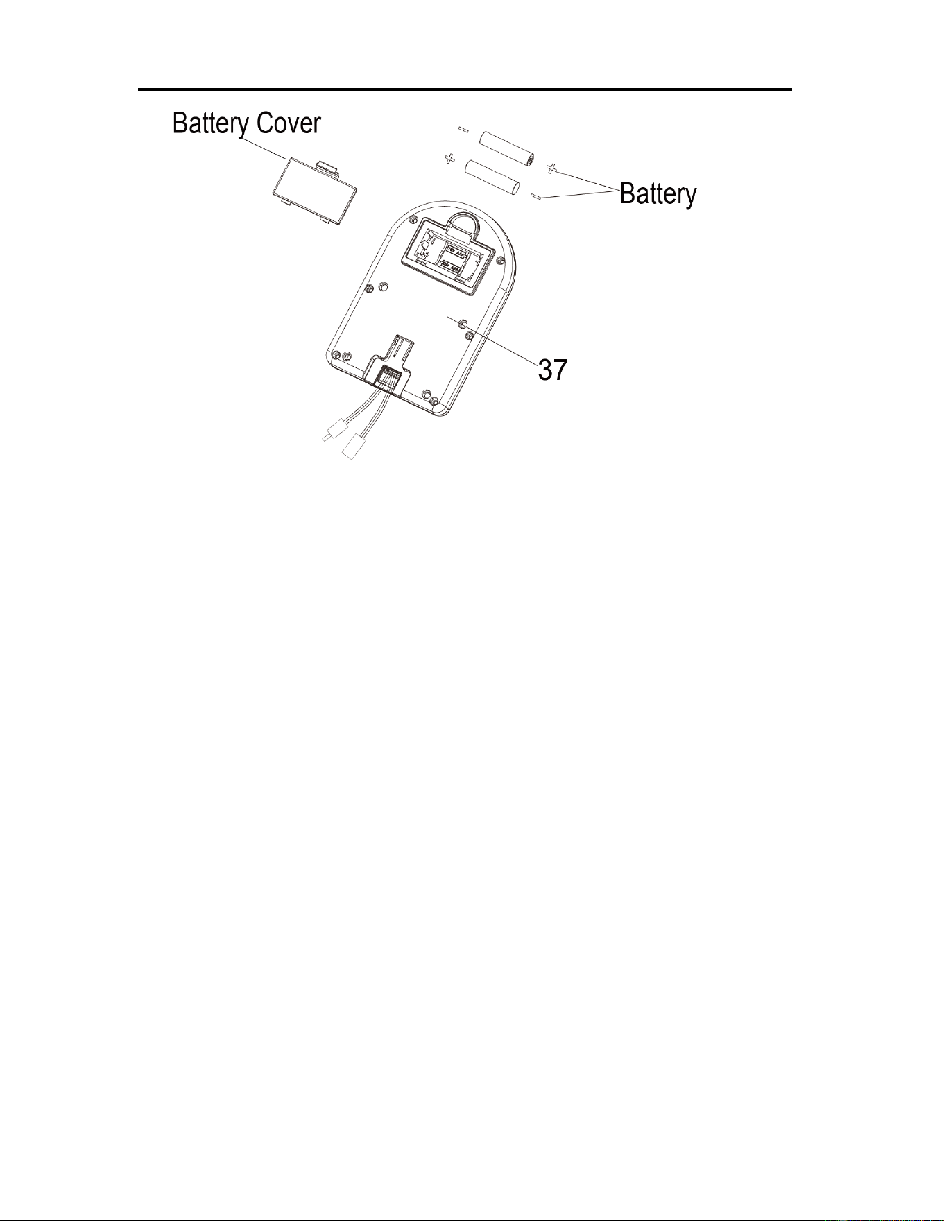
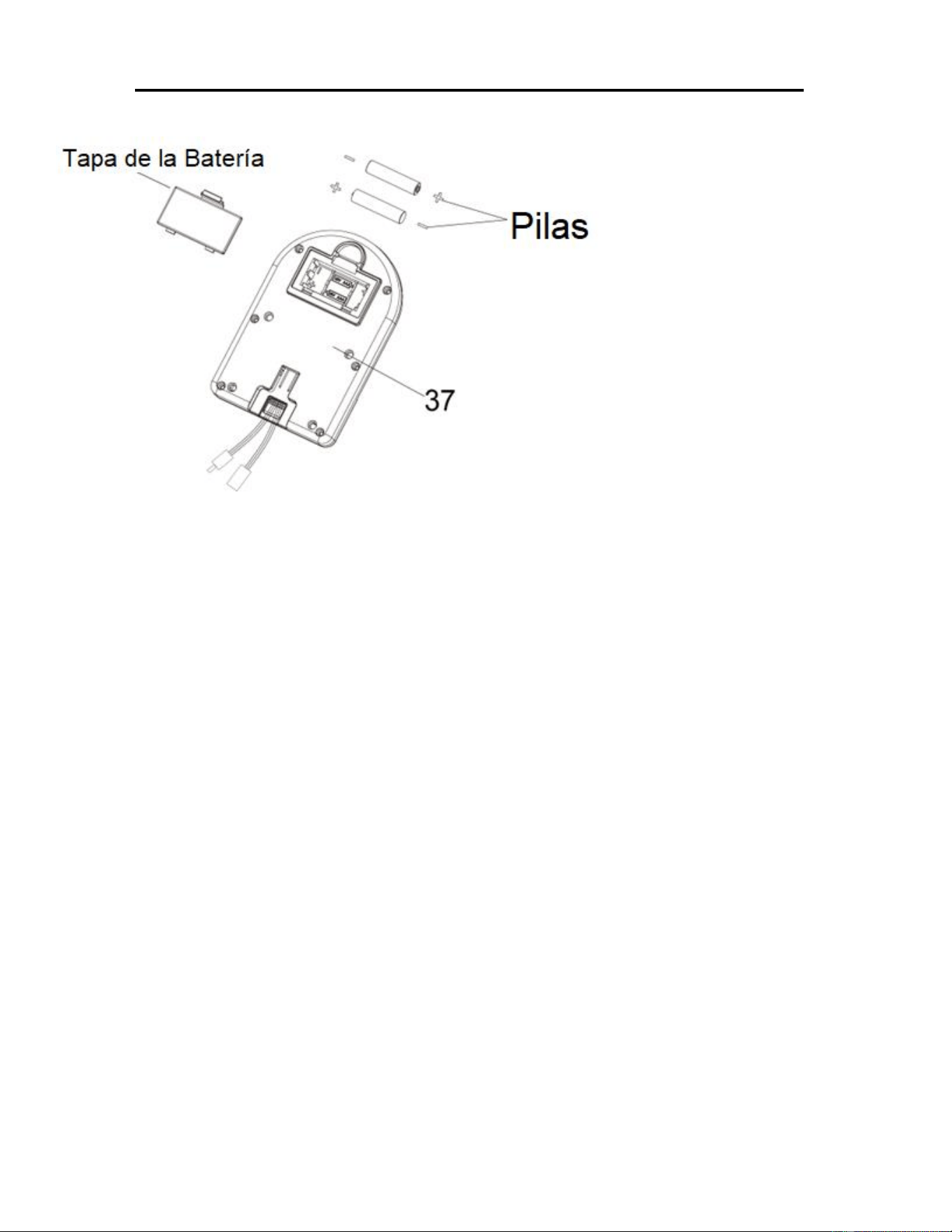
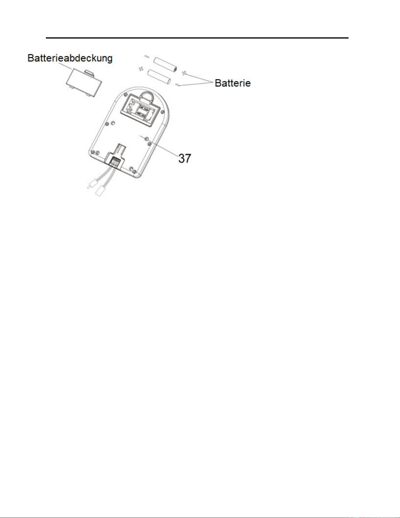
BATTERY INSTALLATION & REPLACEMENT
BATTERY INSTALLATION:
1. Take out 2 AAA batteries from computer box.
2. Press the buckle of battery cover on the back of the Computer (No. 37), then remove battery
cover.
3. Install 2 AAA batteries into the battery case on the back of the Computer (No. 37). Pay attention
to the battery + and – poles before installing.
4. Press the buckle of battery cover, then put the battery cover back to the back of the Computer
(No. 37).
The installation is complete!
BATTERY REPLACEMENT:
1. Press the buckle of battery cover on the back of the Computer (No. 37), then remove battery
cover.
2. Remove the 2 old AAA batteries in the battery case and install 2 new AAA batteries into the
battery case on the back of the Computer (No. 37). Pay attention to the battery + and – poles
before installing.
3. Press the buckle of battery cover, then put the battery cover back to the back of the Computer
(No. 37).
The replacement is complete!
NOTE: Always change both batteries at the same time. Do not mix battery types and do not mix old
and new batteries. Dispose batteries according to your state and regional guidelines.
10
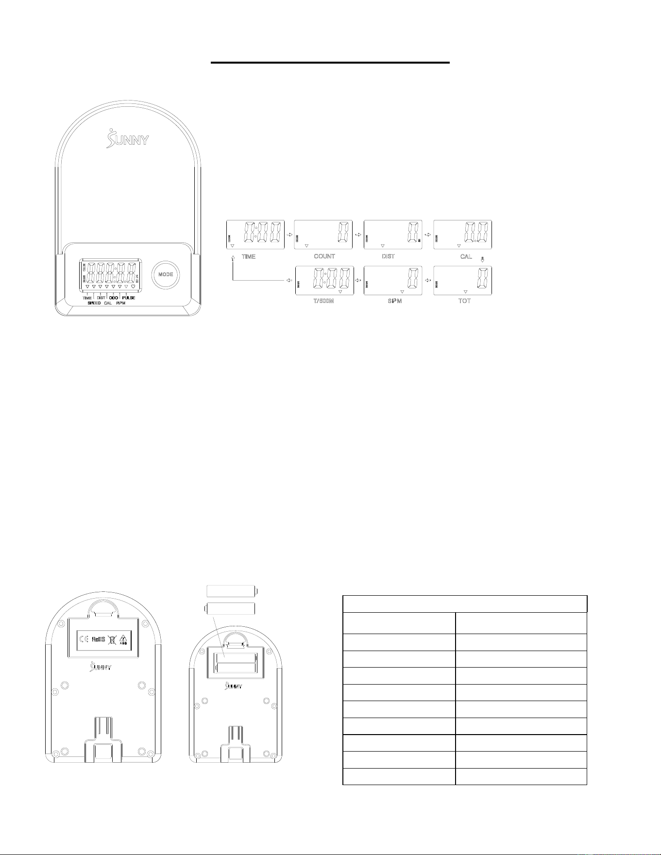
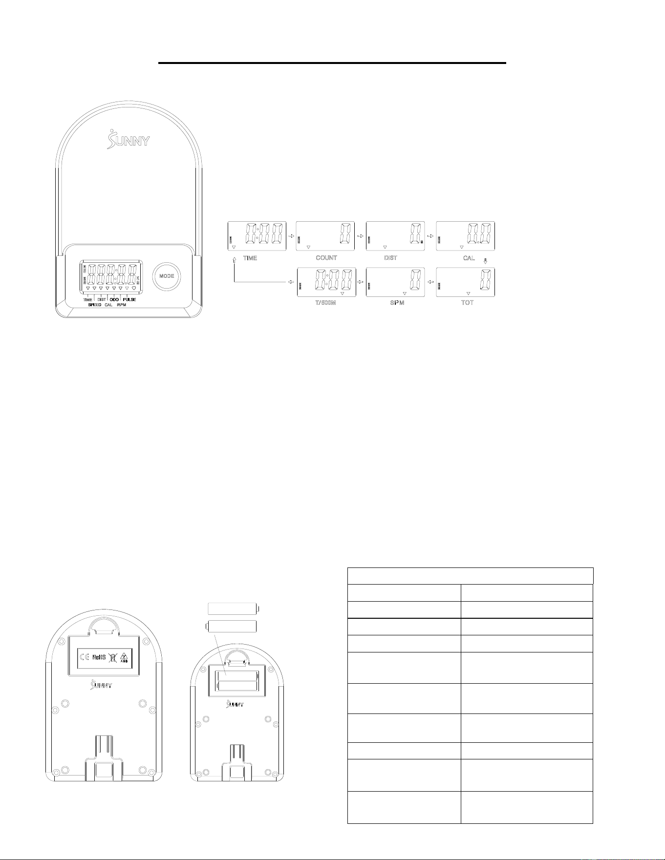
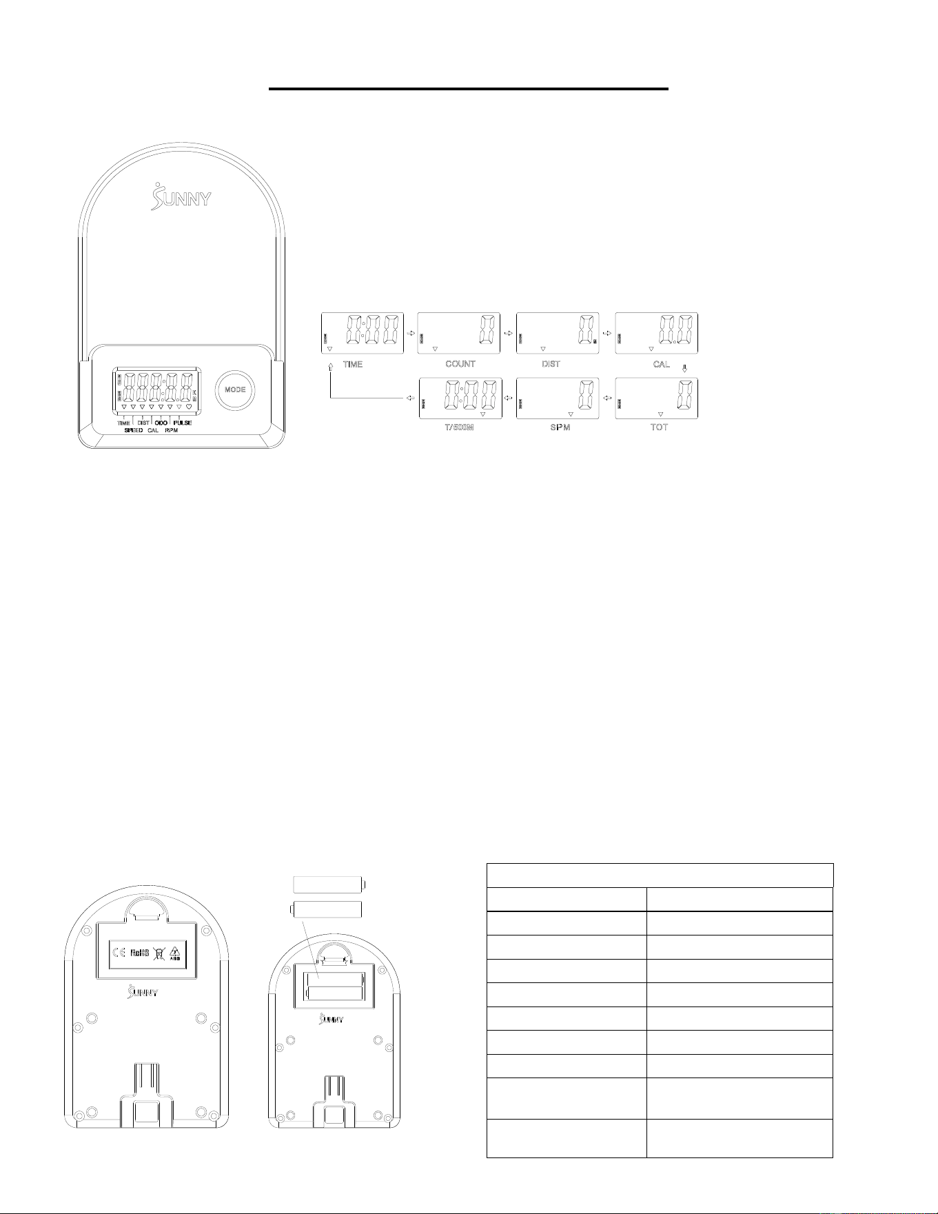
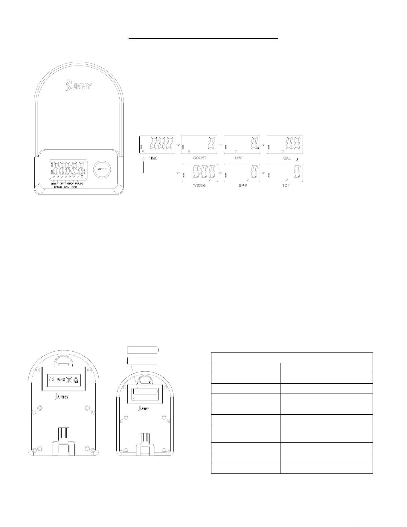
EXERCISE COMPUTER
■KEY FUNCTIONS:
⚫ Press the MODE key to select and lock on a function for following sequence:
SCAN→TIME→ COUNT→ DIST→ CAL→ TOTAL COUNT (TOT) → SPM→T/500M→SCAN
⚫ Press and hold the MODE key for 3 seconds to reset the value to zero (without TOT).
■SLEEP MODE:
⚫ The system turns on when MODE key is pressed and system senses a signal input from the sensor.
⚫ The system turns off automatically when the sensor has no signal input or no key are pressed for approximately 4
minutes.
■FUNCTIONS:
⚫ SCAN: Display changes according to the next diagram every 6 seconds.
⚫ COUNT: The current count from starting exercise.
⚫ DIST: The current distance from starting exercise.
⚫ TIME: The total working times elapsed from starting exercise.
⚫ TOTAL COUNT (TOT): The total count from first inserting batteries
⚫ CALORIES: The calorie burned from starting exercise.
⚫ SPM: Number of strokes per minute, indicating the stroke speed during exercise.
⚫ T/500M: The time for 500 meters during exercise
■ BATTERY INSTALLATION & REPLACEMENT
SPECIFICATION
SCAN
6S
TIME
999M:59S
COUNT
0~65535
DIST
0~65535 Meters
TOT
0~65535
CALORIES
0.0~9999.9 Kcal
SPM
0~299
BATTERY
SIZE-AAA *2
Operating temperature
0~40℃(32℉-104℉)
Storage temperature
-10~60℃(14℉-140℉)
11
APP CONNECTION:
CONNECT SMART EQUIPMENT TO SUNNYFIT APP:
1. Scan to download SunnyFit from the app store.
2. Ensure that the Bluetooth function is turned on from your mobile device.
3. If this is your first time using the SunnyFit app, follow the in-app instructions to register for your
free SunnyFit account and log in.
4. Begin any workout activity that matches your smart equipment, then follow the onscreen prompts
to search for and connect to your smart equipment.
5. When connected, your stats and records will be displayed at the end of your course/session, and
recorded in your account profile!
TROUBLESHOOTING:
•
If you are having trouble connecting your smart equipment, visit www.sunnyfit.com/guide or
scan the QR code below:
•
If you require additional support, please contact [email protected].

12
PARTS LIST
No.
Description
Spec.
Qty.
No.
Description
Spec.
Qty.
1
Main Frame
1
38
Bolt
M5*10
7
2
Sliding Rail
1
39
Sensor Wire
L=310mm
1
3
Front Stabilizer
1
39A
Sensor Wire A
1
4
Rear Stabilizer
1
39B
Sensor Wire B
1
5
Handlebar
Φ28*1.5
1
40
Bolt
Φ14*77.5*M8
1
6
Seat
1
41
Axle Sleeve
2
7
Washer
Ф8*Ф16*1.5
19
42
Big Washer
Φ8*Φ25*2.0
1
8
Spring Washer
Ф8
6
43
Foot Pad
M8*30*Φ52*19
1
9
Bolt
M8*20
10
44
Nut
M8*B4
2
10
Seat Supporting Board
2
45
Bolt
M6*55
1
11
U Shape Bracket
2
46
Shaft Snap Ring
2
12
Bolt
M8*100
3
47
Belt Pulley Shaft
1
13
Spacer
Ф15*Ф8*4
6
48
Bearing
6000
2
14
Bearing
608
6
49
Mesh Belt Pulley
1
15
Wheel
3
50
Washer
Φ6*Φ12*1.0
1
16
Casing Pipe for Idler Wheel
3
51
Nut
M6
1
17
Nut
M8
6
52
Handle Guide
1
18
Adjusting Screw
M6*36
4
53
Round End Cap
2
19
U Shape Baffle
4
54
Foam Grip
Φ27*Φ33*244
2
20
Nut
M6 S10
4
55
Nut
M10*1.0*9
4
21
Bolt
M8*16
4
56
Nut
M10*1
4
22
End Cap
4
57
Volute Spring Complete
Set
1
23
Nut
M8
4
58
Mesh Belt
1
24
Foot Pad
φ38*18-M8*25
4
59
Inertial Wheel
1
25
Square Plug
1
60
Belt
220PJ
1
26
Limit Mat
Ф22*16
2
61
Tension Control Knob
L=310mm
1
27
Screw
M6*20
2
62
Washer
Φ5
1
28
Bolt
M12*160
4
63
Bolt
M5*12
1
29L
Left Pedal
1
64
Left Cover
1
29R
Right Pedal
1
65
Right Cover
1
30
Pedal Strap
2
66
Bottle holder
1
31
Bolt
M8*20S6
2
67
Cover
2
32
Bolt
M8*40
2
68
Screw
ST4.2*20
6
33
Transportation Wheel
2
69
Screw
ST4.2*25
7
34
Computer Supporting Tube
1
70
Shipping Board
1
35
Bolt
M8*10
2
71
Screw
M8*10
2
36
Computer Support
1
72
Plastic Washer
Ф8*Ф20*2.0
2
37
Computer
1
73
Allen Wrench
S6
1
37A
Computer Wire A
1
74
Spanner
S10,13,14,15
1
37B
Computer Wire B
1
75
Spanner
S10,13,17,19
1

13
INFORMACIÓN IMPORTANTE DE SEGURIDAD
Gracias por haber elegido nuestro producto. Para garantizar su seguridad y salud, utilice este
equipo correctamente. Es importante que lea todo el manual antes de instalar y usar el equipo.
Solo se puede garantizar el uso seguro y eficaz del equipo si se instala, mantiene y utiliza
correctamente. Es su responsabilidad asegurarse de que todos los usuarios de los equipos
conozcan todas las advertencias y precauciones.
1. Antes de comenzar algún programa de ejercicios, deberá consultar con su médico para
determinar si tiene alguna condición médica o física que pudiera poner en riesgo su salud y
seguridad o que pudiera impedir que utilice correctamente el equipo. Es importante que reciba
las recomendaciones de su médico en caso de que esté tomando algún medicamento que
pudiera afectar su ritmo cardíaco, presión arterial o nivel de colesterol.
2. Esté atento a las señales que le envía su cuerpo. Ejercitarse de manera incorrecta o excesiva
puede dañar su salud. Deje de hacer ejercicio si experimenta alguno de los siguientes síntomas:
dolor, opresión en el pecho, latidos cardíacos irregulares, falta de aliento, sensación de
desmayo, mareos o sensación de náuseas. Si presenta alguna de esas condiciones, deberá
consultar con su médico antes de continuar con su programa de ejercicios.
3. Mantenga el equipo lejos del alcance de niños y mascotas. El equipo está diseñado para el uso
exclusivo de adultos.
4. Utilice el equipo en una superficie plana y sólida con una cubierta protectora para su piso o
alfombra. Para garantizar su seguridad, el equipo debe tener por lo menos 2 pies (60 CM) de
espacio libre a su alrededor.
5. Asegúrese de que todas las tuercas y pernos estén bien ajustados antes de usar el equipo. Solo
puede conservarse la seguridad del equipo si se inspecciona regularmente para detectar daños
o desgaste.
6. Siempre utilice el equipo como se indica. Si encuentra algún componente defectuoso mientras
instala o revisa el equipo, o si escucha ruidos extraños que provienen de este mientras se
ejercita, deje de utilizarlo inmediatamente y no lo utilice hasta que el problema se haya
corregido.
7. Use ropa adecuada cuando utilice el equipo. Evite usar ropa suelta que pueda enredarse en el
equipo.
8. No coloque los dedos u objetos en las piezas móviles del equipo.
9. La capacidad de peso máximo de esta unidad es de 285 libras (130 kgs).
10. Este equipo no es adecuado para uso terapéutico.
11. Muévase con cuidado cuando levante y mueva el equipo. Siempre utilice la técnica de
levantamiento adecuada y pida ayuda en caso de que sea necesario.
12. Su producto está diseñado para usarse en un lugar fresco y seco. Debe evitar tenerlo en
lugares extremadamente fríos, calientes o húmedos, ya que podría provocar corrosión y otros
problemas afines.
13. Este equipo está diseñado solo para uso interior; no es para uso comercial.
14
LISTA DE VERIFICACIÓN PREVIA AL ENSAMBLADO
Antes de comenzar a ensamblar, asegúrese de que todas las piezas estén incluidas.
n.°
Descripción
Especific.
Cant.
n.°
Descripción
Especific.
Cant.
1
Marco Principal
1
29L
Pedal Izquierdo
1
2
Riel Deslizante
1
29R
Pedal Derecho
1
3
Estabilizador
Delantero
1
A
Paquete de
Herramientas
1
4
Estabilizador
Trasero
1
B
Tarjeta de
Agradecimiento
1
6
Asiento
1
C
Manual
1
36
Soporte para
Computadora
1
D
AAA Pilas
2
37
Computadora
1

15
PAQUETE DE HERRAMIENTAS
Pedido de piezas de repuesto (solo para clientes de EE. UU. y Canadá)
Proporcione la siguiente información para que podamos identificar con precisión las piezas
necesarias:
✓ El número de modelo (se encuentra en la portada del manual).
✓ El nombre del producto (se encuentra en la portada del manual).
✓ El número de pieza que se encuentra en el “ESQUEMA DE LAS PIEZAS” (páginas 61-62) y en la
“LISTA DE PIEZAS” (página 24).
Contáctenos en [email protected] o 1-877-90SUNNY (877-907-8669).
16
INSTRUCCIONES DE ENSAMBLADO
Valoramos su experiencia con los productos de Sunny Health and Fitness. Para asistencia con
repuestos o solución de problemas, contáctenos en [email protected] o al 1-877-
90SUNNY (877-907-8669).
PASO 2:
Fije el Estabilizador Delantero (n.° 3) al
Marco Principal (n.° 1) usando 2 Pernos
(n.° 9) y 2 Arandelas (n.° 7). Ajuste y
asegure con la Llave Allen (n.° 73).
PASO 1:
Desatornille 2 Tornillos (n.° 71), 2
Arandelas de Plástico (n.° 72) y 1 Tablero
de Envío (n.° 70) del Marco Principal (n.° 1)
con la Llave Allen (n.° 73).
Puede guardar estas piezas Tornillos
(n.° 71), Arandelas de Plástico (n.° 72),
Tablero de Envío (n.° 70)] en caso de que
desee volver a empaquetar y transportar este
equipo en el futuro.
17
Valoramos su experiencia con los productos de Sunny Health and Fitness. Para asistencia con
repuestos o solución de problemas, contáctenos en [email protected] o al 1-877-
90SUNNY (877-907-8669).
PASO 3:
Fije 2 Pernos (n.° 28) al orificio inferior en la
posición B del Marco Principal (n.° 1) con la
Llave Inglesa (n.° 75).
Inserte 2 Pernos (n.° 28) en el orificio
superior en la posición A del Marco
Principal (n.° 1) a través de los 2 Pedales
(n.° 29L/R). Ajuste con la Llave Inglesa
(n.° 75).
NOTA: Los 2 Pedales (n.° 29L/R) deben
descansar sobre los Pernos (n.° 28) que
están en la posición B.
PASO 4:
Deslice el Asiento (n.° 6) en el Riel
Deslizante (n.° 2).
Fije 1 Tapete de Límite (n.° 26) en el Riel
Deslizante (n.° 2) usando 1 Tornillo (n.° 27);
luego, ajuste con la Llave Inglesa (n.° 74).
PASO 5:
Fije el Estabilizador Trasero (n.° 4) al Riel
Deslizante (n.° 2) usando 4 Pernos (n.° 21) y
4 Arandelas (n.° 7). Ajuste y asegure con la
Llave Allen (n.° 73).
18
Valoramos su experiencia con los productos de Sunny Health and Fitness. Para asistencia con
repuestos o solución de problemas, contáctenos en [email protected] o al 1-877-
90SUNNY (877-907-8669).
PASO 6:
Fije el Riel Deslizante (n.° 2) al Marco
Principal (n.° 1) asegurando 2 Pernos
(n.° 31) en los lados izquierdo y derecho del
Marco Principal (n.° 1). No ajuste los
Pernos (n.° 31) ahora.
Asegure 4 Pernos (n.° 9) y 4 Arandelas
(n.° 7) a la parte inferior del Marco Principal
(n.° 1). Ajuste los 4 Pernos (n.° 9) y los 2
Pernos (n.° 31) con la Llave Allen (n.° 73)
ahora.
PASO 7:
Retire 4 Pernos (n.° 38) de la parte posterior
de la Computadora (n.° 37) con la Llave
Inglesa (n.° 74).
Inserte primero los Cables de la
Computadora A/B (n.° 37A/B) a través del
Soporte para Computadora (n.° 36), a
continuación ije la Computadora (n.° 37) al
Soporte para Computadora (n.° 36) usando
los 4 Pernos (n.° 38) que se extrajeron. Ajuste
y asegure con la Llave Inglesa (n.° 74).
Conecte el Cable del Sensor A (n.° 39A) al
Cable de Computadora A (n.° 37A) y
conecte el Cable del Sensor B (n.° 39B) al
Cable de Computadora B (n.° 37B). A
continuación, inserte el cable conectado en el
Caño del Soporte de la Computadora
(n.° 34).
Fije el Soporte para Computadora (n.° 36) al
Caño del Soporte de la Computadora
(n.° 34) usando 2 Pernos (n.° 35) y 2
Arandelas de Resorte (n.° 8). Ajuste y
asegure con la Llave Allen (n.° 73) y la Llave
Inglesa (n.° 74).
¡El ensamblado está completo!
19
AJUSTES Y GUÍA DE USO
PRECAUCIÓN Las partes móviles, como el asiento, pueden cortar y aplastar. Mantenga las
manos alejadas del riel deslizante durante el uso.
AJUSTE DE LA CORREA DEL PEDAL
La correa del pedal es ajustable y se puede
personalizar para adaptarse al tamaño del pie del
usuario.
NOTA: Para evitar lesiones, ajuste las correas de los
pedales al pie del usuario antes del ejercicio.
TRASLADO DE LA REMADORA
Para trasladar la remadora, levante el Estabilizador
Trasero (n.° 4) hasta que las ruedas de transporte
del Estabilizador Delantero (n.° 3) toquen el piso.
Con las ruedas de transporte en el suelo, puede
transportar la remadora al lugar deseado con
facilidad.
AJUSTE DEL MONITOR Y LA RESISTENCIA
Ajuste las Almohadillas para Pies (n.° 24) en el
soporte trasero de la remadora si la remadora se
desequilibra durante el uso.
Gire la Perilla de Control de Tensión (n.° 61) hacia
la derecha para aumentar el nivel de resistencia. Gire
la Perilla de Control de Tensión (n.° 61) hacia la
izquierda para reducir el nivel de resistencia.
Los niveles de tensión se configuran entre el Nivel 1,
que es el más bajo, y el Nivel 8, que es el más alto.
20
GUÍA DE ALMACENAMIENTO
PRECAUCIÓN
Tenga cuidado al colocar
verticalmente el Riel
Deslizante (n.° 2), ya que su
cabeza puede tocar el
Estabilizador Trasero (n.° 4).
Cuando no esté en uso,
puede ahorrar espacio
colocando la remadora
en posición vertical en el
piso con la Almohadilla
para Pies (n.° 43).
SEGURIDAD
NOTA: El Asiento
(n.° 6) se deslizará hacia
abajo al colocar el Riel
Deslizante (n.° 2) en
posición vertical.
PRECAUCIÓN
El Asiento (n.° 6) se deslizará hacia
abajo al colocar el Riel Deslizante
(n.° 2) en posición vertical.
2
21
INSTALACIÓN Y REEMPLAZO DE LAS PILAS
INSTALACIÓN DE LAS PILAS:
1. Saque 2 pilas AAA de la caja de la computadora.
2. Presione el broche de la cubierta de las pilas en la parte posterior de la Computadora (n.° 37); luego,
retire la cubierta de las pilas.
3. Instale 2 pilas AAA en la caja de las pilas en la parte posterior de la Computadora (n.° 37). Preste
atención a los polos + y - de las pilas antes de instalarlas.
4. Presione el broche de la cubierta de las pilas y, luego, vuelva a colocar la tapa en la parte posterior de la
Computadora (n.° 37).
¡La instalación está completa!
CAMBIO DE PILAS:
1. Presione el broche de la cubierta de las pilas en la parte posterior de la Computadora (n.° 37); luego,
retire la cubierta de las pilas.
2. Retire las 2 pilas AAA viejas de la caja de las pilas e instale 2 pilas AAA nuevas en la caja de las pilas en
la parte posterior de la Computadora (n.° 37). Preste atención a los polos + y - de las pilas antes de
instalarlas.
3. Presione el broche de la cubierta de las pilas y, luego, vuelva a colocar la tapa en la parte posterior de la
Computadora (n.° 37).
¡El cambio está completo!
NOTA: Cambie siempre ambas pilas al mismo tiempo. No mezcle tipos de pilas y tampoco mezcle pilas
viejas y nuevas. Deseche las pilas de acuerdo con las pautas regionales y estatales.
22
COMPUTADORA DE EJERCICIOS
■ UNCIONES PRINCIPALES:
⚫ Presione la tecla MODE (MODO) para seleccionar y bloquear una función para la siguiente secuencia:
SCAN (ESCANEO)→TIME (TIEMPO)→ COUNT (CONTEO)→ DIST (DISTANCIA)→ CAL (CALORÍAS)→ TOTAL COUNT,
TOT (CONTEO TOTAL) → SPM (GOLPES POR MINUTO)→T/500M →SCAN (ESCANEO)
⚫ Mantenga pulsada la tecla MODE (MODO) durante 3 segundos para reconfigurar el valor a cero (sin TOT).
■ SLEEP MODE (MODO DE SUSPENSIÓ N):
⚫ El sistema se enciende cuando se pulsa la tecla MODE (MODO) y el sistema detecta una señal entrante del sensor. 9
⚫ El sistema se apaga automáticamente cuando el sensor no tiene ninguna señal entrante o no se pulsa ninguna tecla durante
aproximadamente 4 minutos.
■ FUNCIONES:
⚫ SCAN (ESCANEO): La pantalla cambia de acuerdo con el siguiente diagrama cada 6 segundos.
⚫ COUNT (CONTEO): El conteo actual desde el inicio del ejercicio.
⚫ DIST (DISTANCIA): La distancia actual desde el inicio del ejercicio.
⚫ TIME (TIEMPO): El tiempo total de ejercicio transcurrido desde el inicio del ejercicio.
⚫ TOTAL COUNT (CONTEO TOTAL, TOT): El conteo total desde la primera vez que se insertaron las pilas.
⚫ CALORIES (CALORÍAS): Las calorías quemadas desde el inicio del ejercicio.
⚫ SPM (GOLPES POR MINUTO): Número de golpes por minuto, que indica la velocidad de los golpes durante el ejercicio.
⚫ T/500M: El tiempo para 500 metros durante el ejercicio.
■ INSTALACIÓN Y REEMPLAZO DE LAS PILAS
ESPECIFICACIÓN
SCAN (ESCANEO)
6 S
TIME (TIEMPO)
999 M:59 S
COUNT (CONTEO)
0~65535
DIST (DISTANCIA)
0~ 65535 metros
TOT (CONTEO
TOTAL)
0~65535
CALORIES
(CALORÍAS)
0.0~9999.9 Kcal
SPM (GOLPES POR
MINUTO)
0~299
PILAS
TAMAÑO-AAA *2
Temperatura de
operación
0~40 ℃ (32 ℉-104 ℉)
Temperatura de
almacenamiento
-10~60 ℃ (14 ℉-140 ℉)
23
CONEXIÓN A LA APP:
CONECTE EL EQUIPO INTELIGENTE A LA SUNNYFIT APP:
1. Escanee para descargar SunnyFit de la tienda de aplicaciones:
2. Asegúrese de que la función Bluetooth está activada desde su dispositivo móvil.
3. Si es la primera vez que utiliza la aplicación SunnyFit, siga las instrucciones de la aplicación
para registrarse en su cuenta gratuita de SunnyFit e inicie sesión.
4. Comience cualquier actividad de entrenamiento que coincida con su equipo inteligente y, a
continuación, siga las indicaciones en pantalla para buscar y conectarse a su equipo
inteligente.
5. Una vez conectado, sus estadísticas y récords se mostrarán al final de su curso/sesión y se
registrarán en el perfil de su cuenta.
SOLUCIÓN DE PROBLEMAS:
•
Si tienes problemas para conectar tu equipo inteligente, visita www.sunnyfit.com/guide o
escanea el siguiente código QR:
• Si necesitas más ayuda, ponte en contacto con [email protected].

24
LISTA DE PIEZAS
n.°
Descripción
Especific.
Cant.
n.°
Descripción
Especific.
Cant.
1
Marco Principal
1
38
Perno
M5*10
7
2
Riel Deslizante
1
39
Cable del Sensor
L=310 mm
1
3
Estabilizador Delantero
1
39A
Cable del Sensor A
1
4
Estabilizador Trasero
1
39B
Cable de Sensor B
1
5
Manubrio
Φ28*1.5
1
40
Perno
Φ14*77.5*M8
1
6
Asiento
1
41
Cubierta del Eje
2
7
Arandela
Ф8*Ф16*1.5
19
42
Arandela Grande
Φ8*Φ25*2.0
1
8
Arandela de Resorte
Ф8
6
43
Almohadilla Para Pies
M8*30*Φ52*19
1
9
Perno
M8*20
10
44
Tuerca
M8*B4
2
10
Tablero de Soporte del
Asiento
2
45
Perno
M6*55
1
11
Soporte en Forma de U
2
46
Anillo Elástico del Eje
2
12
Perno
M8*100
3
47
Eje de la Polea de Cinta
1
13
Espaciador
Ф15*Ф8*4
6
48
Rodamiento
6000
2
14
Rodamiento
608
6
49
Polea de la Cinta de Red
1
15
Rueda
3
50
Arandela
Φ6*Φ12*1.0
1
16
Tubería de Revestimiento
para Rueda Inactiva
3
51
Tuerca
M6
1
17
Tuerca
M8
6
52
Guía de la Manija
1
18
Tornillo de Ajuste
M6*36
4
53
Tapa de Extremo Redonda
2
19
Bafle en Forma de U
4
54
Agarre de Espuma
Φ27*Φ33*214
2
20
Tuerca
M6 S10
4
55
Tuerca
M10*1.0*9
4
21
Perno
M8*16
4
56
Tuerca
M10*1
4
22
Tapa de Extremo
4
57
Juego Completo de
Resortes de Voluta
1
23
Tuerca
M8
4
58
Cinta de Red
1
24
Almohadilla Para Pies
φ38*18-M8*25
4
59
Rueda de Inercia
1
25
Tapón Cuadrado
1
60
Cinta
220PJ
1
26
Tapete de Límite
Ф22*16
2
61
Perilla de Control de
Tensión
L=310 mm
1
27
Tornillo
M6*20
2
62
Arandela
Φ5
1
28
Perno
M12*160
4
63
Perno
M5*12
1
29L
Pedal Izquierdo
1
64
Cubierta Izquierda
1
29R
Pedal Derecho
1
65
Cubierta Derecha
1
30
Correa del Pedal
2
66
Soporte para Botella
1
31
Perno
M8*20 S6
2
67
Cubierta
2
32
Perno
M8*40
2
68
Tornillo
ST4.2*20
6
33
Rueda de Transporte
2
69
Tornillo
ST4.2*25
7
34
Caño de Soporte de la
Computadora
1
70
Tablero de Envío
1
35
Perno
M8*10
2
71
Tornillo
M8*10
2
36
Soporte para Computadora
1
72
Arandela de Plástico
Ф8*Ф20*2.0
2
37
Computadora
1
73
Llave Allen
S6
1
37A
Cable de la Computadora A
1
74
Llave Inglesa
S10,13,14,15
1
37B
Cable de la Computadora B
1
75
Llave Inglesa
S10,13,17,19
1

25
INFORMATIONS DE SÉCURITÉ IMPORTANTES
Nous vous remercions d’avoir choisi notre produit. Pour votre santé et votre sécurité, veuillez
utiliser correctement cet appareil. Il est important de lire entièrement le présent manuel avant
d’assembler l’appareil et de l’utiliser. L’utilisation sûre et efficace n’est possible que si l’appareil est
correctement assemblé, entretenu et utilisé. Il vous incombe de vous assurer que tous les
utilisateurs de l’appareil soient informés de tous les avertissements et précautions.
1. Avant d’entamer un programme d’exercices, consultez votre médecin pour déterminer si vous
avez une quelconque disposition physique ou médicale susceptible de mettre en danger votre
santé et votre sécurité ou de vous empêcher d’utiliser cet appareil correctement. L’avis de votre
médecin est essentiel si vous prenez un médicament pouvant affecter le rythme cardiaque, la
pression ou le niveau de cholestérol.
2. Soyez conscient des signaux de votre corps. Des exercices incorrects ou excessifs peuvent
nuire à votre santé. Arrêtez l'exercice si vous ressentez l'un des symptômes suivants : douleur,
oppression thoracique, pouls irrégulier, essoufflement, étourdissements, vertiges ou nausées. Si
vous rencontrez l'une de ces conditions, vous devriez consulter votre médecin avant de
poursuivre votre programme d'exercices
3. Gardez les enfants et les animaux de compagnie à distance de l’appareil. L’appareil est conçu
pour l’utilisation exclusive par des adultes.
4. Utilisez l’appareil sur une surface dure, plane et de niveau, avec une protection pour votre
parquet ou tapis. Pour un usage sûr, l’appareil doit disposer d’au moins 60 cm (2 pi) d’espace
libre tout autour de lui.
5. Assurez-vous que tous les boulons et écrous soient bien serrés avant d’utiliser l’appareil. La
sécurité de l’appareil ne peut être entretenue qu’à condition de régulièrement vérifier l’absence
de dommages ou d’usure.
6. Utilisez toujours l'équipement comme indiqué. Si vous trouvez des composants défectueux lors
de l'assemblage ou du contrôle de l'équipement, ou si vous entendez des bruits inhabituels
provenant de l'équipement pendant l'exercice, arrêtez immédiatement d'utiliser l'équipement et
n'utilisez plus jusqu'à ce que le problème soit résolu.
7. Portez des vêtements adéquats lors de l’utilisation de l’appareil. Évitez les vêtements amples qui
risqueraient de se prendre dans l’appareil.
8. Ne mettez pas le doigt ni aucun objet dans les pièces mobiles de l’appareil.
9. La capacité de poids maximale de cet appareil est de 130 kgs (285 lbs).
10. Cet appareil n’est pas adapté à un usage thérapeutique.
11. Soulevez et déplacez l’appareil avec précaution. Utilisez toujours les techniques adéquates de
levage et demandez de l’aide si nécessaire.
12. Votre produit est conçu pour usage dans un endroit sec et frais. Éviter de l’entreposer dans un
endroit extrêmement froid, chaud ou humide, car cela peut entraîner de la corrosion et des
problèmes du même ordre.
13. Cet appareil est conçu pour un usage intérieur uniquement; Il n’est pas fait pour une utilisation
commerciale.
26
LISTE DE CONTRÔLE PRÉ-MONTAGE
Avant de commencer le montage, veuillez vous assurer que toutes les pièces sont fournies.
N
o
Description
Spéc.
Qté
N
o
Description
Spéc.
Qté
1
Cadre Principal
1
29L
Pédale Gauche
1
2
Rail Coulissant
1
29R
Pédale Droite
1
3
Stabilisateur Avant
1
A
Paquet de Visserie
1
4
Stabilisateur Arrière
1
B
Carte de
Remerciement
1
6
Selle
1
C
Manuel
1
36
Support de
l’Ordinateur
1
D
Piles
2
37
Ordinateur
1

27
PAQUET DE VISSERIE
Pour commander des pièces de rechange (clients américains et canadiens seulement)
Veuillez fournir les informations suivantes afin que nous puissions identifier avec précision la pièce ou
les pièces requise(s):
✓ Le numéro de modèle (situé sur la couverture du manuel)
✓ Le nom du produit (situé sur la couverture du manuel)
✓ Le numéro de pièce figurant sur le « SCHÉMA ÉCLATÉ » (pages 61-62) et la « LISTE DES
ÉLÉMENTS » (page 36)
Veuillez nous contacter à [email protected] ou 1-877-90SUNNY (877-907-8669).
28
INSTRUCTIONS D’ASSEMBLAGE
Nous apprécions votre expérience d'utilisation des produits Sunny Health and Fitness. Pour obtenir
de l'aide concernant des pièces ou un dépannage, veuillez nous contacter à
[email protected] ou au 1-877-90SUNNY (877-907-8669).
ÉTAPE 2 :
Fixer le Stabilisateur Avant (N
o
3) au Cadre
Principal (N
o
1) avec 2 Boulons (N
o
9) et
2 Rondelles (N
o
7). Bien serrer avec la Clé
Allen (N
o
73).
ÉTAPE 1 :
Dévissez 2 Vis (N
o
71), 2 Rondelles en
Plastique (N
o
72) et 1 Panneau
d’Expédition (N
o
70) du Cadre Principal
(N
o
1) à l’aide d’une Clé Allen (N
o
73).
Vous pouvez conserver ces pièces Vis
(N
o
71), Rondelles en Plastique (N
o
72),
Panneau d’Expédition (N
o
70) au cas où
vous voudriez remballer cet appareil pour le
transporter.

29
Nous apprécions votre expérience d'utilisation des produits Sunny Health and Fitness. Pour obtenir
de l'aide concernant des pièces ou un dépannage, veuillez nous contacter à
[email protected] ou au 1-877-90SUNNY (877-907-8669).
ÉTAPE 3 :
Fixer 2 Boulons (N° 28) dans l’orifice
inférieur à la position B du Cadre Principal
(N° 1) avec la clé à écrous (n° 75).
Insérer 2 Boulons (N° 28) dans l’orifice
supérieur à la position A du Cadre Principal
(N° 1) à travers les 2 Pédales (N° 29L/R).
Serrer avec la Clé à Écrous (N
o
75).
REMARQUE : Les 2 Pédales (N° 29L/R)
devraient reposer sur les Boulons (N° 28)
qui sont à la position B.
ÉTAPE 4 :
Fixer la Selle (N
o
6) au Rail Coulissant
(N
o
2).
Fixer 1 Tampon Limite (N
o
26) au Rail
Coulissant (N
o
2) à l’aide de 1 Vis (N
o
27),
puis serrer avec la Clé à Écrous (N
o
74).
ÉTAPE 5 :
Fixer le Stabilisateur Arrière (N
o
4) au Rail
Coulissant (N
o
2) avec 4 Boulons (N
o
21) et
4 Rondelles (N
o
7). Bien serrer avec la Clé
Allen (N
o
73).
30
Nous apprécions votre expérience d'utilisation des produits Sunny Health and Fitness. Pour obtenir
de l'aide concernant des pièces ou un dépannage, veuillez nous contacter à
[email protected] ou au 1-877-90SUNNY (877-907-8669).
ÉTAPE 6 :
Fixer le Rail Coulissant (N
o
2) au Cadre
Principal (N
o
1) en fixant 2 Boulons (N
o
31)
sur les côtés gauche et droit du Cadre
Principal (N
o
1). Ne pas serrer les Boulons
(N
o
31) tout de suite.
Fixer 4 Boulons (N
o
9) et 4 Rondelles (N
o
7)
au bas du Cadre Principal (N
o
1). Serrer
maintenant les 4 Boulons (N
o
9) et les
2 Boulons (N
o
31) avec la Clé Allen (N
o
73).
ÉTAPE 7 :
Retirer les 4 Boulons (N
o
38) à l’arrière de
l’Ordinateur (N
o
37) à l’aide de la Clé à
Écrous (N
o
74).
Insérez d'abord les Câbles de l’Ordinateur
A/B (N° 37A/B) à travers le Support de
l’Ordinateur (N
o
36), puis fixer l’Ordinateur
(N
o
37) au Support de l’Ordinateur (N
o
36)
avec les 4 Boulons (N
o
38) qui ont été
retirés. Bien serrer avec la Clé à Écrous
(N
o
74).
Connecter le Câble du Capteur A (N
o
39A)
au Câble de l’Ordinateur A (N
o
37A) et
connecter le Câble du Capteur B (n
o
39B)
au Câble de l’Ordinateur B (N
o
37B).
Ensuite, insérer le câble connecté dans le
Tube de Support de l’Ordinateur (N
o
34).
Fixer le Support de l’Ordinateur (N
o
36) au
Tube de Support de l’Ordinateur (N
o
34) à
l’aide de 2 Boulons (N
o
35) et 2 Rondelles-
ressorts (N
o
8). Bien serrer avec la Clé
Allen (N
o
73) et la Clé à Écrous (n
o
74).
Le montage est terminé !
31
RÉGLAGES ET GUIDE D’UTILISATION
ATTENTION ! Les pièces mobiles, telles que la selle, peuvent causer des écrasements et des
coupures. Ne pas mettre les mains sur le rail coulissant pendant l’utilisation !
RÉGLAGE DE LA COURROIE DE PÉDALE
La courroie de pédale est réglable et peut s’adapter à
la taille du pied de l’utilisateur.
REMARQUE : Afin d’éviter toute blessure, veuillez
régler les courroies de pédale par rapport aux pieds
de l’utilisateur avant l’exercice.
DÉPLACER LE RAMEUR
Pour déplacer le rameur, soulever le Stabilisateur
Arrière (N
o
4) jusqu’à ce que les roulettes de
transport du Stabilisateur Avant (N
o
3) touchent le
sol. Une fois les roulettes de transport au sol,
déplacer le rameur jusqu’à l’emplacement souhaité.
RÉGLER L’ÉQUILIBRE ET LA RÉSISTANCE
Si le rameur est déséquilibré pendant l’utilisation,
régler les Patins de Pied (N° 24) sur le support
arrière du rameur.
Tourner le Bouton de Contrôle de la Tension
(N
o
61) dans le sens des aiguilles d’une montre pour
augmenter le niveau de résistance. Tourner le
Bouton de Contrôle de la Tension (N
o
61) dans le
sens des aiguilles d’une montre pour réduire le
niveau de résistance.
Les niveaux de tension vont du niveau 1 (le plus
faible) au niveau 8 (le plus élevé).
32
GUIDE DE RANGEMENT
ATTENTION !
Placer verticalement le Rail
Coulissant (N° 2) avec
précaution, car votre tête peut
toucher le Stabilisateur
Arrière (N° 4).
Lorsque vous n’utilisez
pas le rameur, vous
pouvez gagner de la
place en le plaçant
debout sur le sol grâce
aux Patins de Pieds
(N
o
43).
SÉCURITÉ
REMARQUE : La Selle
(N
o
6) glissera vers le
bas lors du placement
du Rail Coulissant
(N
o
2) en position
verticale.
ATTENTION !
La Selle (N
o
6) glissera vers le bas lors
du placement du Rail Coulissant
(N
o
2) en position verticale.
2

33
INSTALLATION ET REMPLACEMENT DES PILES
INSTALLATION DES PILES :
1. Retirer les 2 piles de type AAA du boîtier de l’ordinateur.
2. Appuyer sur le fermoir du couvercle du compartiment à piles situé à l’arrière de l’Ordinateur (N
o
37) et
retirer le couvercle.
3. Installer 2 piles de type AAA dans le compartiment à piles situé à l’arrière de l’Ordinateur (N
o
37). Vérifier
les pôles (+) et (-) des piles avant de les installer.
4. Appuyer sur le fermoir du couvercle du compartiment à piles et remettre le couvercle à l’arrière de
l’Ordinateur (N
o
37).
L’installation est terminée !
REMPLACEMENT DES PILES :
1. Appuyer sur le fermoir du couvercle du compartiment à piles situé à l’arrière de l’Ordinateur (N
o
37) et
retirer le couvercle.
2. Retirer les 2 anciennes piles du compartiment à piles situé à l’arrière de l’Ordinateur (N
o
37) et installer
2 piles de type AAA neuves. Vérifier les pôles (+) et (-) des piles avant de les installer.
3. Appuyer sur le fermoir du couvercle du compartiment à piles et remettre le couvercle à l’arrière de
l’Ordinateur (N
o
37).
Le remplacement est terminé !
REMARQUE : Toujours changer les deux piles en même temps. Toujours utiliser des piles du même type et
ne pas mélanger les piles neuves avec les anciennes. Jeter les piles conformément aux directives
provinciales et régionales.
34
ORDINATEUR D’EXERCICE
■FONCTIONS PRINCIPALES :
⚫ Appuyer sur la touche MODE pour sélectionner et verrouiller une fonction pour la séquence suivante :
SCAN (BALAYAGE)→TIME (TEMPS)→ COUNT (NOMBRE)→ DIST→ CAL→ TOTAL COUNT (NOMBRE TOTAL) (TOT)
→ SPM→T/500M →SCAN (BALAYAGE)
⚫ Appuyer sur la touche MODE et la maintenir enfoncée pendant 3 secondes pour remettre la valeur à zéro (sans TOT).
■MODE VEILLE :
⚫ Le système se met en marche lorsque vous appuyez sur la touche MODE et que le système détecte un signal provenant
du capteur.
⚫ Le système s’éteint automatiquement lorsque le capteur ne reçoit aucun signal ou que vous n’appuyez sur aucune touche
pendant environ 4 minutes.
■FONCTIONS :
⚫ SCAN (BALAYAGE) : L’affichage change toutes les 6 secondes selon le schéma suivant.
⚫ COUNT (NOMBRE) : Le nombre actuel du depuis le début de l’exercice.
⚫ DIST (DISTANCE) : La distance actuelle depuis le début de l’exercice.
⚫ TIME (TEMPS) : Le temps d’entraînement total écoulé depuis le début de l’exercice.
⚫ NOMBRE TOTAL (TOT) : Le nombre total depuis la première insertion des piles.
⚫ CALORIES : Les calories brûlées depuis le début de l’exercice.
⚫ SPM : Le nombre de mouvements par minute, indiquant la vitesse de mouvement pendant l’exercice.
⚫ T/500M : Le temps pour 500 mètres durant l’exercice
■INSTALLATION ET REMPLACEMENT DES PILES
SPÉCIFICATION
SCAN (BALAYAGE)
6S
TIME (TEMPS)
999M:59S
COUNT (NOMBRE)
0~65535
DIST
0~65535 Meters
TOT
0~65535
CALORIES
0.0~9999.9 Kcal
SPM
0~299
BATTERY (PILES)
SIZE-AAA *2
Température de
Fonctionnement
0~40℃(32℉-104℉)
Température de
Rangement
-10~60℃(14℉-140℉)

35
CONNEXION À L'APPLICATION :
CONECTE EL EQUIPO INTELIGENTE A LA SUNNYFIT APP:
1. Scannez pour télécharger SunnyFit à partir de l'app store:
2. Assurez-vous que la fonction Bluetooth est activée sur votre appareil mobile.
3. Si vous utilisez l'application SunnyFit pour la première fois, suivez les instructions in-app pour
vous inscrire à votre compte SunnyFit gratuit et vous connecter.
4. Commencez toute activité d'entraînement correspondant à votre équipement intelligent, puis
suivez les invites à l'écran pour rechercher votre équipement intelligent et vous y connecter.
5. Une fois connecté, vos statistiques et vos records seront affichés à la fin de votre
cours/session et enregistrés dans le profil de votre compte !
DÉPANNAGE:
•
Si vous ne parvenez pas à connecter votre équipement intelligent, visitez le site
www.sunnyfit.com/guide ou scannez le code QR ci-dessous:
• Si vous avez besoin d'une assistance supplémentaire, veuillez contacter

36
LISTE DES PIÈCES
N
o
Description
Spéc.
Qté
N
o
Description
Spéc.
Qté
1
Cadre Principal
1
38
Boulon
M5 x 10
7
2
Rail Coulissant
1
39
Câble de Capteur
L = 310 mm
1
3
Stabilisateur Avant
1
39 A
Câble de Capteur A
1
4
Stabilisateur Arrière
1
39B
Câble de Capteur B
1
5
Guidon
Ø28 x 1,5
1
40
Boulon
Ø14 x 77,5 x M8
1
6
Selle
1
41
Manchon d’Axe
2
7
Rondelle
Ø8 × Ø16 x 1,5
19
42
Grande Rondelle
Ø8 x Ø25 x 2,0
1
8
Rondelle-ressort
Ø8
6
43
Patin de Pied
M8 x 30 x Ø52 x 19
1
9
Boulon
M8 x 20
10
44
Écrou
M8 x B4
2
10
Panneau de Support de
Selle
2
45
Boulon
M6 x 55
1
11
Support en U
2
46
Circlip d’Arbre
2
12
Boulon
M8 x 100
3
47
Arbre de Poulie de
Courroie
1
13
Entretoise
Ø15 x Ø8 x 4
6
48
Roulement
6000
2
14
Roulement
608
6
49
Poulie de Courroie en
Maille
1
15
Roue
3
50
Rondelle
Ø6 x Ø12 x 1,0
1
16
Tuyau de Revêtement de
Roue Libre
3
51
Écrou
M6
1
17
Écrou
M8
6
52
Guide de Poignée
1
18
Vis de Réglage
M6 x 36
4
53
Embout d’Extrémité Rond
2
19
Chicane en U
4
54
Poignée en Mousse
Ø27 x Ø33 x 214
2
20
Écrou
M6 S10
4
55
Écrou
M10 x 1,0 x 9
4
21
Boulon
M8 x 16
4
56
Écrou
M10 x 1
4
22
Embout d’Extrémité
4
57
Ensemble Complet de
Ressorts en Volute
1
23
Écrou
M8
4
58
Courroie en Maille
1
24
Patin de Pied
Ø38 x 18-
M8 x 25
4
59
Roue d’Inertie
1
25
Bouchon Carré
1
60
Courroie
220PJ
1
26
Tampon Limite
Ø22 x 16
2
61
Bouton de Contrôle de la
Tension
L = 310 mm
1
27
Vis
M6 x 20
2
62
Rondelle
Ø5
1
28
Boulon
M12 x 160
4
63
Boulon
M5 x 12
1
29L
Pédale Gauche
1
64
Carter Gauche
1
29R
Pédale Droite
1
65
Carter Droit
1
30
Courroie de Pédale
2
66
Porte-Bouteille
1
31
Boulon
M8 x 20 S6
2
67
Couvercle
2
32
Boulon
M8 x 40
2
68
Vis
ST4,2 x 20
6
33
Roulette de Transport
2
69
Vis
ST4,2 x 25
7
34
Tube de Support de
l’Ordinateur
1
70
Panneau d’Expédition
1
35
Boulon
M8 x 10
2
71
Vis
M8 x 10
2
36
Support de l’Ordinateur
1
72
Rondelle en Plastique
Ø8 x Ø20 x 2,0
2
37
Ordinateur
1
73
Clé Allen
S6
1
37A
Câble d’Ordinateur A
1
74
Clé à Écrous
S10, 13, 14, 15
1
37B
Câble d’Ordinateur B
1
75
Clé à Écrous
S10,13,17,19
1

37
WICHTIGE SICHERHEITSHINWEISE
Wir danken Ihnen, dass Sie sich für unser Produkt entschieden haben. Zur Gewährleistung Ihrer
Sicherheit und Gesundheit verwenden Sie dieses Gerät bitte ordnungsgemäß. Es ist wichtig, diese
gesamte Bedienungsanleitung zu lesen, bevor Sie das Gerät montieren und in Betrieb nehmen. Eine
sichere und effektive Nutzung kann nur erreicht werden, wenn das Gerät ordnungsgemäß montiert,
gewartet und verwendet wird. Sie sind dafür verantwortlich, dass alle Benutzer des Geräts über alle
Warnungen und Vorsichtsmaßnahmen informiert werden.
1. Vor Beginn eines jeden Trainingsprogramms ist es ratsam, einen Arzt zu konsultieren, um
festzustellen, ob Sie medizinische oder körperliche Beschwerden haben, die Ihre Gesundheit
und Sicherheit gefährden oder verhindern könnten, dass Sie das Gerät ordnungsgemäß
benutzen. Der Rat Ihres Arztes ist unerlässlich, wenn Sie Medikamente einnehmen, die Ihre
Herzfrequenz, Ihren Blutdruck oder Ihren Cholesterinspiegel beeinflussen.
2. Achten Sie auf die Signale Ihres Körpers. Falsches oder übermäßiges Training kann Ihre
Gesundheit schädigen. Hören Sie auf zu trainieren, wenn Sie eines der folgenden Symptome
verspüren: Schmerzen, Engegefühl in Ihrer Brust, unregelmäßiger Herzschlag, Kurzatmigkeit,
Benommenheit, Schwindel oder Übelkeit. Wenn Sie einen dieser Zustände bemerken, sollten
Sie Ihren Arzt konsultieren, bevor Sie mit Ihrem Trainingsprogramm fortfahren.
3. Kinder und Haustiere dürfen nicht in der Nähe des Geräts sein. Das Gerät ist nur für den
Gebrauch durch Erwachsene bestimmt.
4. Verwenden Sie das Gerät auf einer festen, ebenen Fläche mit einer Schutzabdeckung für Ihren
Boden oder Teppich. Um die Sicherheit zu gewährleisten, sollte das Gerät ringsum mindestens
60 cm (2 ft) Freiraum haben.
5. Vergewissern Sie sich, dass alle Muttern und Bolzen fest angezogen sind, bevor Sie das Gerät
benutzen. Die Sicherheit des Gerätes kann nur gewährleistet werden, wenn es regelmäßig auf
Beschädigungen und/oder Verschleißüberprüft wird.
6. Verwenden Sie das Gerät immer entsprechend den Angaben. Wenn Sie bei der Montage oder
Überprüfung des Geräts defekte Komponenten feststellen oder ungewöhnliche Geräusche vom
Gerät während des Trainings hören, stellen Sie die Verwendung des Geräts sofort ein. In
diesem Fall sollten Sie es erst dann wieder in Betrieb nehmen, wenn das Problem behoben ist.
7. Tragen Sie bei der Benutzung des Gerätes geeignete Kleidung. Vermeiden Sie das Tragen von
loser Kleidung, die sich in der Ausrüstung verfangen kann.
8. Stecken Sie keine Finger oder Gegenstände in die beweglichen Teile des Gerätes.
9. Die maximale Gewichtsbelastbarkeit dieser Einheit beträgt 130kgs (285 Pfund).
10. Dieses Gerät ist nicht für den therapeutischen Einsatz geeignet.
11. Um Personenschäden und/oder Schäden am Produkt oder Eigentum zu vermeiden, ist ein
ordnungsgemäßes Hochheben und Transportieren erforderlich.
12. Ihr Produkt ist für den Einsatz unter kühlen und trockenen Bedingungen bestimmt. Sie sollten
die Lagerung in extrem kalten, heißen oder feuchten Räumen vermeiden, da dies zu Korrosion
und anderen damit verbundenen Problemen führen kann.
13. Dieses Gerät ist nur für den Innen- und Heimgebrauch bestimmt; es ist nicht für die gewerbliche
Nutzung bestimmt.
38
CHECKLISTE VOR DER MONTAGE
Vor Zusammenbau gelieferte Teile auf Vollständigkeit prüfen.
Nr.
Bezeichnung
Spezif.
Menge
Nr.
Bezeichnung
Spezif.
Menge
1
Hauptrahmen
1
29L
Linkes Pedal
1
2
Gleitschiene
1
29R
Rechtes Pedal
1
3
Vorderer Stabilisator
1
A
Metallbauteile
1
4
Hinterer Stabilisator
1
B
Dankeskarte
1
6
Sitz
1
C
Bedienungsanleitung
1
36
Computerhalterung
1
D
AAA-Batterie
2
37
Computer
1
39
METALLBAUTEILE
Bestellung von Ersatzteilen (nur für US-amerikanische und kanadische Kunden)
Bitte geben Sie die folgenden Informationen an, damit wir das/die benötigte(n) Teil(e) genau
identifizieren können:
✓ Die Modellnummer (finden Sie auf dem Umschlag der Anleitung)
✓ Die Produktbezeichnung (finden Sie auf dem Umschlag der Anleitung)
✓ Die Teilenummer auf der „EXPLOSIONSDARSTELLUNG“ (Seiten 61-62) und der
“TEILELISTE“ (Seite 48)
Bitte kontaktieren Sie uns unter [email protected] oder 1-877-90SUNNY (877-907-
8669).
40
MONTAGEANLEITUNG
Wir schätzen Ihre Erfahrung im Umgang mit den Produkten von Sunny Health and Fitness. Für
Fragen zu Teilen oder Hilfe bei der Fehlerbehebung kontaktieren Sie uns bitte unter
[email protected] oder 1-877-90SUNNY (877-907-8669).
SCHRITT 2:
Vorderen Stabilisator (Nr. 3) mit 2 Bolzen
(Nr. 9) und 2 Unterlegscheiben (Nr. 7) am
Hauptrahmen (Nr. 1) anbringen. Mit dem
Inbusschlüssel (Nr. 73) hinein drehen und
festziehen.
SCHRITT 1:
Mit dem Inbusschlüssel (Nr. 73) die 2
Schrauben (Nr. 71), die 2 Unterlegscheiben
aus Kunststoff (Nr. 72) und die
Versandpappe (Nr. 70) vom Hauptrahmen
(Nr. 1) entfernen.
Diese Teile Schrauben (Nr. 71),
Unterlegscheiben aus Kunststoff (Nr. 72),
Versandpappe (Nr. 70) für den Fall
aufbewahren, dass das Gerät später wieder
verpackt und transportiert werden soll.

41
Wir schätzen Ihre Erfahrung im Umgang mit den Produkten von Sunny Health and Fitness. Für
Fragen zu Teilen oder Hilfe bei der Fehlerbehebung kontaktieren Sie uns bitte unter
[email protected] oder 1-877-90SUNNY (877-907-8669).
SCHRITT 3:
Die 2 Bolzen (Nr. 28) mit
Schraubenschlüssel (Nr. 75) im unteren
Loch in Position B des Hauptrahmens (Nr.
1) anbringen.
Die 2 Bolzen (Nr. 28) durch die 2 Pedale
(Nr. 29L/R) in das obere Loch in Position A
des Hauptrahmens (Nr. 1) stecken. Mit dem
Schraubenschlüssel (Nr. 75) festziehen.
HINWEIS: Die 2 Pedale (Nr. 29L/R) sollten
auf den Bolzen (Nr. 28) in Position B
aufliegen.
SCHRITT 4:
Den Sitz (Nr. 6) auf die Gleitschiene (Nr. 2)
schieben.
Die Begrenzungsmatte (Nr. 26) mit 1
Schraube (Nr. 27) an der Gleitschiene (Nr.
2) anbringen und mit dem
Schraubenschlüssel (Nr. 74) festziehen.
SCHRITT 5:
Hinteren Stabilisator (Nr. 4) mit 4 Bolzen (Nr.
21) und 4 Unterlegscheiben (Nr. 7) an der
Gleitschiene (Nr. 2) anbringen. Mit dem
Inbusschlüssel (Nr. 73) hinein drehen und
festziehen.

42
Wir schätzen Ihre Erfahrung im Umgang mit den Produkten von Sunny Health and Fitness. Für
Fragen zu Teilen oder Hilfe bei der Fehlerbehebung kontaktieren Sie uns bitte unter
[email protected] oder 1-877-90SUNNY (877-907-8669).
SCHRITT 6:
Gleitschiene (Nr. 2) durch Befestigen von 2
Bolzen (Nr. 31) auf der linken und rechten
Seite von Hauptrahmen (Nr. 1) am
Hauptrahmen (Nr. 1) anbringen. Die Bolzen
(Nr. 31) noch nicht festziehen.
Die 4 Bolzen (Nr. 9) und 4
Unterlegscheiben (Nr. 7) auf der Unterseite
von Hauptrahmen (Nr. 1) befestigen. Alle 4
Bolzen (Nr. 9) und 2 Bolzen (Nr. 31) jetzt mit
dem Inbusschlüssel (Nr. 73) festziehen.
SCHRITT 7:
Die 4 Bolzen (Nr. 38) auf der Rückseite von
Computer (Nr. 37) mit dem
Schraubenschlüssel (Nr. 74) entfernen.
Führen Sie zuerst die Computerkabels A/B
(Nr. 37A/B) durch die Computerhalterung
(Nr. 36), dann Computer (Nr. 37) mit den 4
soeben entfernten Bolzen (Nr. 38) an der
Computerhalterung (Nr. 36) anbringen. Mit
dem Schraubenschlüssel (Nr. 74) hinein
drehen und festziehen.
Die Sensorkabel A (Nr. 39A) mit dem
Computerkabel A (Nr. 37A) und die
Sensorkabel B (Nr. 39 B) mit
Computerkabel B (Nr. 37B) verbinden. Als
Nächstes das angeschlossene Kabel in das
Stützrohr des Computers (Nr. 34)
einführen.
Die Computerhalterung (Nr. 36) mit den 2
Bolzen (Nr. 35) und 2 Federscheiben (Nr. 8)
am Stützrohr des Computers (Nr. 34)
anbringen. Mit dem Inbusschlüssel (Nr. 73)
und Schraubenschlüssel (Nr. 74) hinein
drehen und festziehen.
Die Montage ist abgeschlossen!
43
EINSTELLUNGEN UND GEBRAUCHSANWEISUNG
VORSICHT! Bewegliche Teile, wie z. B. der Sitz, können zu Schnittverletzungen und
Quetschungen führen. Bei Gebrauch Hände von der Gleitschiene fernhalten!
PEDALRIEMEN-EINSTELLUNG
Die Pedalriemen sind verstellbar und können an die
Fußgröße des Benutzers angepasst werden.
HINWEIS: Zur Vermeidung von Verletzungen
Pedalriemen vor dem Training an den Fuß des
Benutzers anpassen.
TRANSPORT DES RUDERGERÄTS
Zum Bewegen des Rudergeräts den Hinteren
Stabilisator (Nr. 4) heben, bis die Transportrollen
am Vorderen Stabilisator (Nr. 3) Bodenkontakt
haben. Jetzt lässt sich das Rudergerät mühelos an
den neuen Standort rollen.
EINSTELLEN VON GLEICHGEWICHT UND
WIDERSTAND
Bei ungleichem Lauf des Rudergeräts die
Fußpolster (Nr. 24) an der hinteren Stütze justieren.
Den Drehknopf der Bandzugregelung (Nr. 61) im
Uhrzeigersinn drehen, um den Widerstand zu
erhöhen. Den Drehknopf der Bandzugregelung
(Nr. 61) im Gegenuhrzeigersinn drehen, um den
Widerstand zu verringern.
Die Zugkraft kann zwischen Level 1 (am niedrigsten)
und Level 8 (am höchsten) eingestellt werden.

44
AUFBEWAHRUNGSHINWEISE
VORSICHT!
Es ist möglich, sich beim
unachtsamen Aufrichten der
Gleitschiene (Nr. 2) den Kopf
am Hinteren Stabilisator (Nr.
4) zu stoßen.
Bei Nichtgebrauch lässt
sich das Rudergerät
platzsparend senkrecht
auf Fußpolster (Nr. 43)
stellen.
SICHERHEITS
HINWEIS: Der Sitz (Nr.
6) rutscht beim
Aufrichten der
Gleitschiene (Nr. 2)
nach unten.
VORSICHT!
Der Sitz (Nr. 6) rutscht beim Aufrichten
der Gleitschiene (Nr. 2) nach unten.
2
45
EINLEGEN UND AUSTAUSCHEN DER BATTERIE
EINLEGEN DER BATTERIEN:
1. Die 2 AAA-Batterien aus dem Computerfach nehmen.
2. Klipp der Batterieabdeckung auf der Rückseite des Computers (Nr. 37) herunter drücken und
dann die Batterieabdeckung entfernen.
3. 2 AAA Batterien in das Batteriefach auf der Rückseite von Computer (Nr. 37) einlegen. Vor
Einsetzen der Batterie auf die Pole + und – achten.
4. Klipp der Batterieabdeckung herunter drücken und die Batterieabdeckung wieder in die Rückseite
von Computer (Nr. 37) einsetzen.
Das Einlegen der Batterien ist abgeschlossen!
AUSTAUSCHEN DER BATTERIEN:
1. Klipp der Batterieabdeckung auf der Rückseite des Computers (Nr. 37) herunter drücken und
dann die Batterieabdeckung entfernen.
2. Die 2 alten AAA Batterien aus dem Batteriefach entfernen und 2 neue AAA Batterien in das
Batteriefach auf der Rückseite von Computer (Nr. 37) einlegen. Vor Einsetzen der Batterie auf
die Pole + und – achten.
3. Klipp der Batterieabdeckung herunter drücken und die Batterieabdeckung wieder in die Rückseite
von Computer (Nr. 37) einsetzen.
Das Austauschen der Batterien ist abgeschlossen!
HINWEIS: Immer beide Batterien gleichzeitig austauschen. Weder Batterietypen noch alte und
neue Batterien kombinieren. Batterien gemäß staatlichen und regionalen Richtlinien entsorgen.
46
TRAININGSCOMPUTER
■HAUPTFUNKTIONEN:
⚫ MODE-Taste drücken, um eine Funktion aus der folgenden Sequenz auszuwählen und zu verfolgen:
SCAN→TIME→ COUNT→ DIST→ CAL→ TOTAL COUNT (TOT) →SPM →T/500M →SCAN
⚫ MODE-Taste 3 Sekunden gedrückt halten, um den Wert auf Null zurückzusetzen (außer TOT).
■ENERGIESPARMODUS:
⚫ Das System wird per Druck auf die MODE-Taste und Empfang eines Sensorsignals eingeschaltet.
⚫ Das System wird automatisch ausgeschaltet, wenn kein Sensorsignal empfangen oder ca. 4 Min. keine Taste gedrückt wird.
■FUNKTIONEN:
⚫ SCAN: Anzeige wechselt alle 6 Sekunden zum nächsten Diagramm.
⚫ COUNT: Die aktuelle Zählung seit Trainingsbeginn.
⚫ DIST: Die aktuelle Entfernung seit Trainingsbeginn.
⚫ TIME: Bisherige Dauer des Trainings.
⚫ TOTAL COUNT (TOT): Die Gesamtzahl ab dem ersten Einlegen der Batterien.
⚫ CALORIES: Kalorienverbrauch seit Trainingsbeginn.
⚫ SPM: Schlagzahl pro Minute, das Rudertempo während des Trainings.
⚫ T/500M: Trainingszeit für 500 Meter.
■ EINLEGEN UND AUSTAUSCHEN DER BATTERIE
TECHNISCHE DATEN
SCAN
6 s
ZEIT (TIME)
999 min:59 s
ZÄHLUNG (COUNT)
0~65535
DISTANZ (DIST)
0~65535Meter
GESAMTZAHL (TOT)
0~65535
KALORIEN
0,0~9999,9 kCal
SCHLAGZAHL PRO
MINUTE (SPM)
0~299
BATTERIE
2 x AAA
Betriebstemperatur
0~40℃ (32℉–104℉)
Lagerungstemperatur
-10~60℃ (14℉–140℉)

47
CONNESSIONE ALL'APP:
COLLEGARE SMART EQUIPMENT A SUNNYFIT APP:
1. Scansionare per scaricare SunnyFit dall'app store:
2. Assicurarsi che la funzione Bluetooth sia attivata dal dispositivo mobile.
3. Se è la prima volta che si utilizza l'app SunnyFit, seguire le istruzioni in-app per registrare il
proprio account SunnyFit gratuito e accedere.
4. Iniziare un'attività di allenamento che corrisponda al proprio smart equipment, quindi seguire le
indicazioni sullo schermo per cercare e connettersi allo smart equipment.
5. Una volta connessi, le statistiche e i record verranno visualizzati alla fine del corso/sessione e
registrati nel profilo dell'account!
RISOLUZIONE DEI PROBLEMI:
•
Se si riscontrano problemi nel collegare l'apparecchiatura smart, visitare il sito
www.sunnyfit.com/guide o scansionare il codice QR qui sotto:
• Se avete bisogno di ulteriore assistenza, contattate [email protected].

48
TEILELISTE
Nr.
Bezeichnung
Spezif.
Menge
Nr.
Bezeichnung
Spezif.
Menge
1
Hauptrahmen
1
38
Bolzen
M5 x 10
7
2
Gleitschiene
1
39
Sensorkabel
L = 310 mm
1
3
Vorderer Stabilisator
1
39A
Sensorkabel A
1
4
Hinterer Stabilisator
1
39B
Sensordraht B
1
5
Holm
Φ 28 x 1,5
1
40
Bolzen
Φ 14 x 77,5 x M8
1
6
Sitz
1
41
Achshülle
2
7
Unterlegscheibe
Ф 8 x Ф16 x 1,5
19
42
Große Unterlegscheibe
Φ 8 x Φ 25 x 2,0
1
8
Federscheibe
Ф 8
6
43
Fußpolster
M8 x 30 x Φ
52 x 19
1
9
Bolzen
M8 x 20
10
44
Schraubenmutter
M8 x B4
2
10
Sitzauflage
2
45
Bolzen
M6 x 55
1
11
U-Klammer
2
46
Wellensicherungsring
2
12
Bolzen
M8 x 100
3
47
Riemenscheibenwelle
1
13
Abstandhalter
Ф 15 x Ф 8 x 4
6
48
Kugellager
6000
2
14
Kugellager
608
6
49
Netzriemenscheibe
1
15
Rad
3
50
Unterlegscheibe
Φ 6 x Φ 12 x 1,0
1
16
Mantelrohr für Leitrad
3
51
Schraubenmutter
M6
1
17
Schraubenmutter
M8
6
52
Griffführung
1
18
Stellschraube
M6 x 36
4
53
Runde Endkappe
2
19
Prallblech in U-Form
4
54
Schaumstoffgriff
Φ 27 x Φ 33 x 214
2
20
Schraubenmutter
M6 S10
4
55
Schraubenmutter
M10 x 1,0 x 9
4
21
Bolzen
M8 x 16
4
56
Schraubenmutter
M10 x 1
4
22
Endkappe
4
57
Kompletter
Schneckenfeder-Satz
1
23
Schraubenmutter
M8
4
58
Netzriemen
1
24
Fußpolster
φ 38 x 18-
M8 x 25
4
59
Inertialrad
1
25
Vierkantstopfen
1
60
Riemen
220PJ
1
26
Begrenzungsmatte
Ф 22 x 16
2
61
Drehknopf der
Bandzugregelung
L = 310 mm
1
27
Schraube
M6 x 20
2
62
Unterlegscheibe
Φ 5
1
28
Bolzen
M12 x 160
4
63
Bolzen
M5 x 12
1
29L
Linkes Pedal
1
64
Linke Abdeckung
1
29R
Rechtes Pedal
1
65
Rechte Abdeckung
1
30
Pedalriemen
2
66
Flaschenhalter
1
31
Bolzen
M8 x 20 S6
2
67
Abdeckung
2
32
Bolzen
M8 x 40
2
68
Schraube
ST 4,2 x 20
6
33
Transportrad
2
69
Schraube
ST 4,2 x 25
7
34
Stützrohr des Computers
1
70
Versandpappe
1
35
Bolzen
M8 x 10
2
71
Schraube
M8 x 10
2
36
Computerhalterung
1
72
Unterlegscheibe auf
Kunststoff
Ф 8 x Ф 20 x 2.0
2
37
Computer
1
73
Inbusschlüssel
S6
1
37A
Computerkabel A
1
74
Schraubenschlüssel
S10,13,14,15
1
37B
Computerkabel B
1

49
IMPORTANTI INFORMAZIONI SULLA SICUREZZA
Grazie per aver scelto il nostro prodotto. Per garantire la sicurezza e la salute dell'utente, si prega
di utilizzare questa attrezzatura in modo corretto. È importante leggere questo manuale per intero
prima di montare e utilizzare l'attrezzatura. Un utilizzo sicuro ed efficace è possibile solo se
l'attrezzatura viene montata, sottoposta a manutenzione e utilizzata correttamente. È responsabilità
dell'utente assicurarsi che tutti gli utilizzatori dell'attrezzatura siano a conoscenza di tutte le
avvertenze e le precauzioni.
1. Prima di iniziare qualsiasi programma di esercizi, è necessario consultare il proprio medico per
determinare se esistono condizioni mediche o fisiche che potrebbero mettere a rischio la salute e
la sicurezza o impedire l'uso corretto dell'attrezzatura. Il parere del medico è fondamentale se si
assumono farmaci che influenzano la frequenza cardiaca, la pressione sanguigna o il livello di
colesterolo.
2. È importante essere consapevoli dei segnali del proprio corpo. Un'attività fisica scorretta o
eccessiva può danneggiare la salute. Interrompere l'attività fisica se si avverte uno dei seguenti
sintomi: dolore, senso di oppressione al petto, battito cardiaco irregolare, mancanza di respiro,
stordimento, vertigini o sensazione di nausea. Se si verifica una di queste condizioni, è
necessario consultare il medico prima di continuare il programma di esercizi.
3. Tenere i bambini e gli animali domestici lontani dall'attrezzatura. L'attrezzatura è progettata solo
per l'uso da parte di adulti.
4. Utilizzare l'attrezzatura su una superficie solida e piana, con una copertura protettiva per il
pavimento o la moquette. Per garantire la sicurezza, l'attrezzatura deve avere almeno 2 piedi
(60 cm) di spazio libero intorno ad essa.
5. Assicurarsi che tutti i dadi e i bulloni siano saldamente serrati prima di utilizzare l'attrezzatura. La
sicurezza dell'attrezzatura può essere mantenuta solo se viene esaminata regolarmente per
verificare la presenza di danni e/o usura.
6. Utilizzare sempre l'attrezzatura come indicato. Se durante il montaggio o il controllo
dell'attrezzatura si riscontrano componenti difettosi o se si sentono rumori insoliti provenire
dall'attrezzatura durante l'esercizio, interrompere immediatamente l'uso dell'attrezzatura e non
utilizzarla finché il problema non è stato risolto.
7. Indossare indumenti adeguati durante l'utilizzo dell'attrezzatura. Evitare di indossare indumenti
larghi che potrebbero impigliarsi nell'attrezzatura.
8. Non inserire dita o oggetti nelle parti mobili dell'attrezzatura.
9. La capacità massima di peso di questa unità è di 285 libbre (130 kgs).
10. L'attrezzatura non è adatta all'uso terapeutico.
11. Per evitare lesioni fisiche e/o danni al prodotto o alle cose, è necessario sollevare e spostare il
prodotto in modo corretto.
12. Il prodotto è destinato all'uso in ambienti freschi e asciutti. Si consiglia di evitare lo stoccaggio in
aree estremamente fredde, calde o umide, poiché ciò potrebbe causare corrosione e altri
problemi correlati.
13. Questa attrezzatura è progettata solo per uso interno e domestico; non è destinata all'uso
commerciale.
50
LISTA DI CONTROLLO PREMONTAGGIO
Prima di iniziare l'assemblaggio, accertarsi che tutte le parti siano incluse.
n.
Descrizione
Spec.
Qtà.
n.
Descrizione
Spec.
Qtà.
1
Telaio principale
1
29L
Pedale Sinistro
1
2
Guida di scorrimento
1
29R
Pedale Destro
1
3
Stabilizzatore anteriore
1
A
Minuteria
1
4
Stabilizzatore posteriore
1
B
Biglietto di ringraziamento
1
6
Seduta
1
C
Manuale
1
36
Supporto computer
1
D
AAA Batteria
2
37
Computer
1
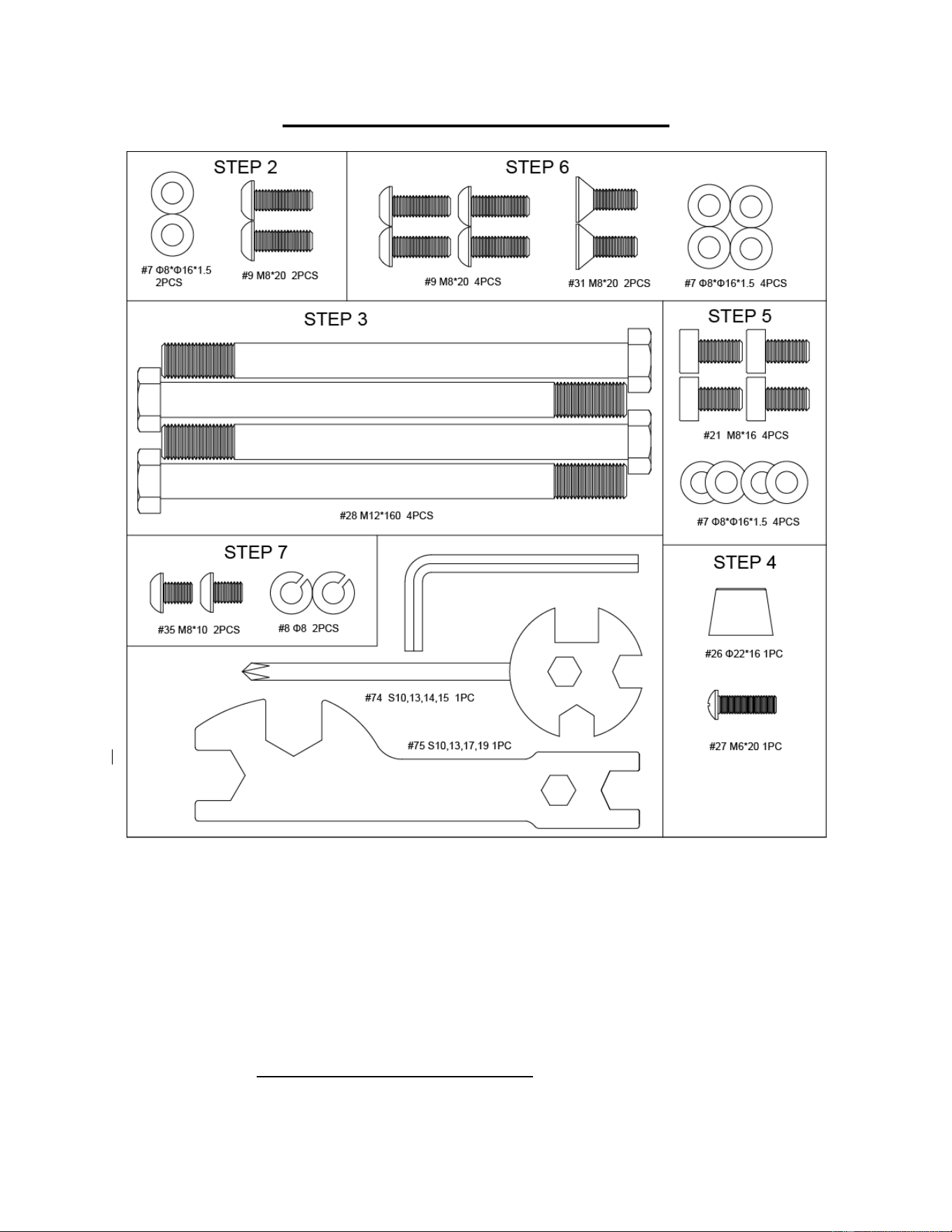
51
PACCHETTO HARDWARE
Come ordinare le parti di ricambio (solo per clienti statunitensi e canadesi)
Fornire le seguenti informazioni per consentirci di identificare con precisione le parti necessarie:
✓ Il numero del modello (si trova sulla copertina del manuale)
✓ Il nome del prodotto (si trova sulla copertina del manuale)
✓ Il codice componente che si trova nello "SCHEMA ESPLOSO" (pagine 61-62) e nell "ELENCO
PARTI" (pagina 60).
Contattateci all'indirizzo [email protected] o al numero 1- 877 - 90SUNNY (877-907-
8669).
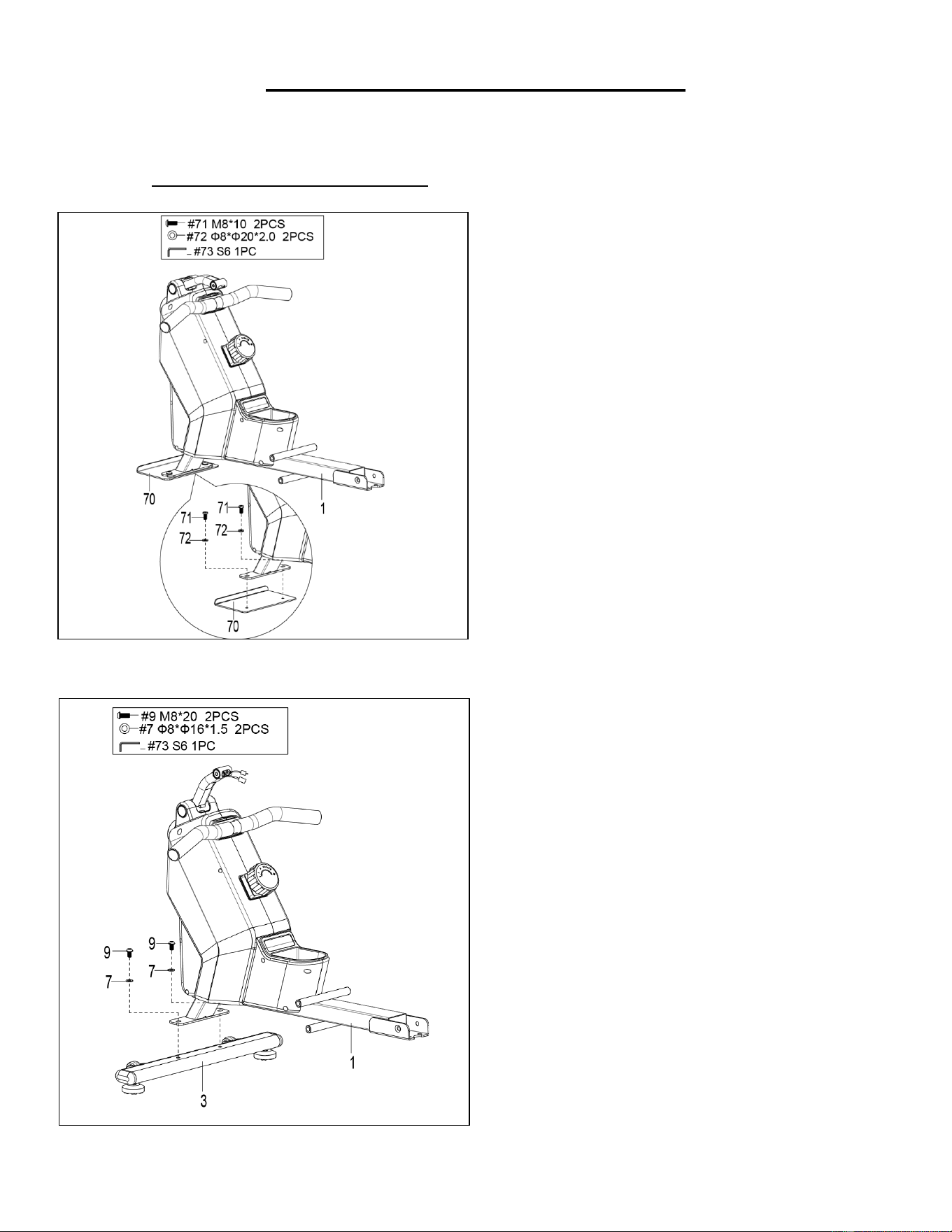
52
ISTRUZIONI DI MONTAGGIO
Teniamo in grande considerazione la vostra esperienza nell'utilizzo dei prodotti Sunny Health and
Fitness. Per assistenza sulle parti di ricambio o per la risoluzione dei problemi, contattateci
FASE 2:
Fissare lo Stabilizzatore Anteriore (n. 3) al
Telaio Principale (n. 1) utilizzando 2 Bulloni
(n. 9) e 2 Rondelle (n. 7). Serrare e fissare
con la Chiave a Brugola (n. 73).
FASE 1:
Svitare 2 Viti (n. 71), 2 Rondelle di Plastica
(n. 72) e 1 Piastra di Spedizione (n. 70) dal
Telaio Principale (n. 1) con la Chiave a
Brugola (n. 73).
Conservare queste parti Viti (n. 71),
Rondelle di Plastica (n. 72), Piastra di
Spedizione (n. 70) nel caso in cui si desideri
imballare nuovamente e trasportare questa
apparecchiatura in futuro.
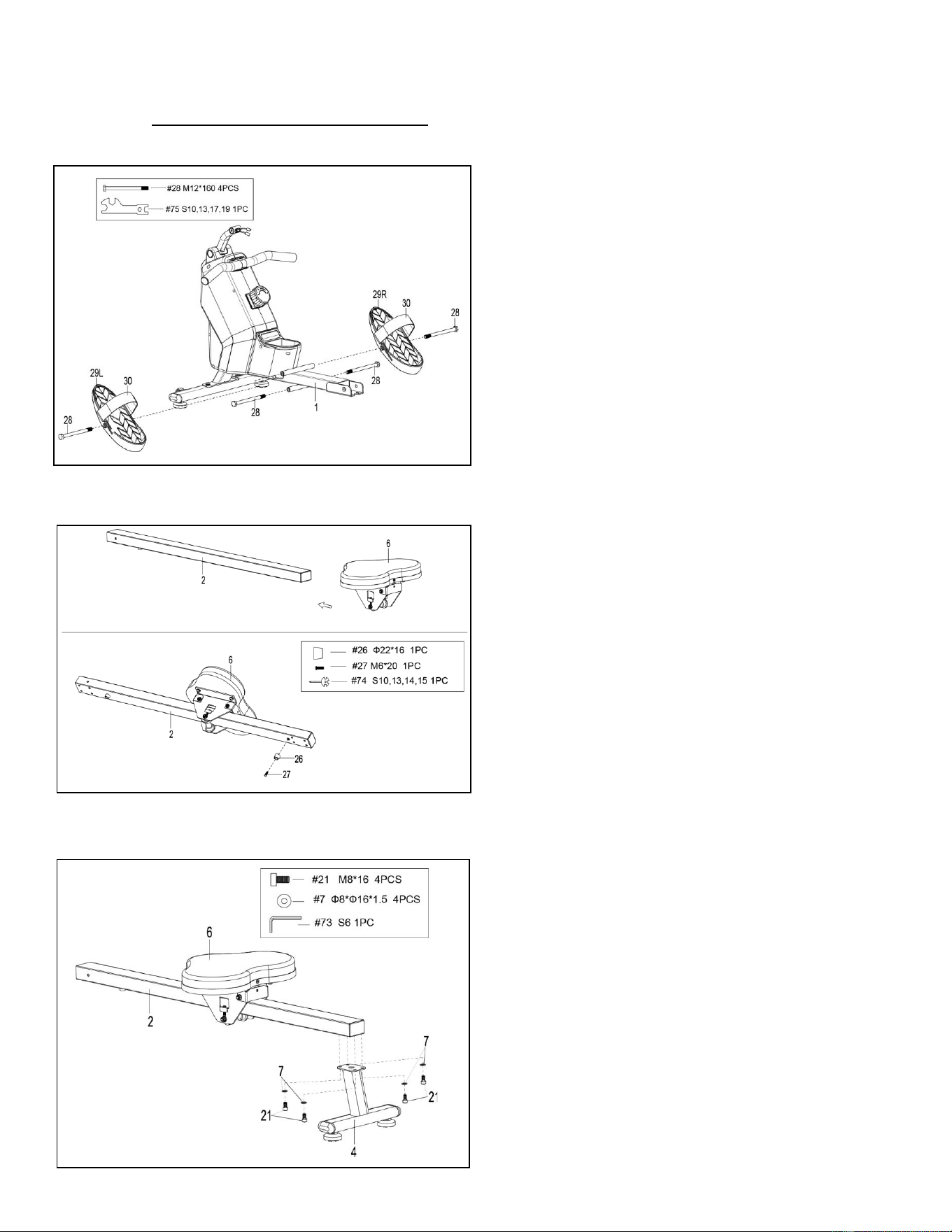
53
Teniamo in grande considerazione la vostra esperienza nell'utilizzo dei prodotti Sunny Health and
Fitness. Per assistenza sulle parti di ricambio o per la risoluzione dei problemi, contattateci
FASE 3:
Fissare 2 Bulloni (n. 28) nel foro inferiore
della posizione B del Telaio Principale (n. 1),
con la Chiave (n. 75).
Inserire 2 Bulloni (n. 28) nel foro superiore
della posizione A del Telaio Principale (n. 1)
attraverso i 2 Pedali (n. 29L/R). Serrare con
la Chiave (n. 75).
NOTA: I 2 Pedali (n. 29L/R) devono poggiare
sui Bulloni (n. 28) che si trovano in posizione
B.
FASE 4:
Far scorrere la Seduta (n. 6) nella Guida di
Scorrimento (n. 2).
Fissare 1 Tampone di Fine Corsa (n. 26)
sulla Guida di Scorrimento (n. 2) con 1 Vite
(n. 27), quindi serrare con la Chiave (n. 74).
FASE 5:
Fissare lo Stabilizzatore Posteriore (n. 4)
alla Guida di Scorrimento (n. 2) utilizzando 4
Bulloni (n. 21) e 4 Rondelle (n. 7). Serrare e
fissare con la Chiave a Brugola (n. 73).
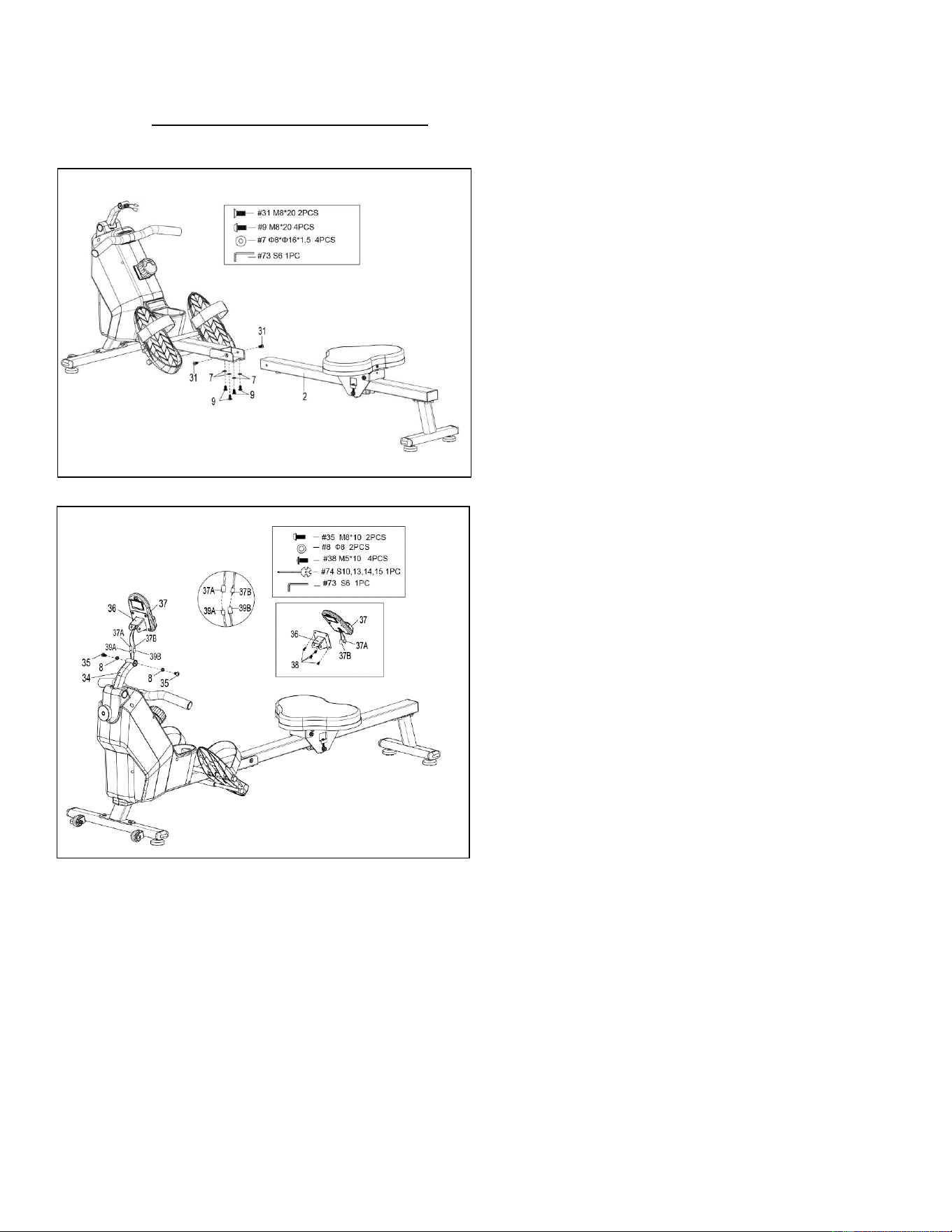
54
Teniamo in grande considerazione la vostra esperienza nell'utilizzo dei prodotti Sunny Health and
Fitness. Per assistenza sulle parti di ricambio o per la risoluzione dei problemi, contattateci
FASE 6:
Fissare la Guida di Scorrimento (n. 2) al
Telaio Principale (n. 1) fissando 2 Bulloni
(n. 31) sui lati destro e sinistro del Telaio
Principale (n. 1). Non serrare ora i Bulloni
(n. 31).
Fissare 4 Bulloni (n. 9) e 4 Rondelle (n. 7)
alla parte inferiore del Telaio Principale (n.
1). Serrare ora tutti i 4 Bulloni (n. 9) e i 2
Bulloni (n. 31) con la Chiave a Brugola (n.
73) .
FASE 7:
Rimuovere i 4 Bulloni (n. 38) dal retro del
computer (n. 37) con la chiave (n. 74).
Inserire prima i Fili del Sensore A/B (n.
37A/B) attraverso il Supporto del Computer
(n. 36), poi fissare il Computer (n. 37) al
Supporto del Computer (n. 36) utilizzando i
4 Bulloni (n. 38) che sono stati rimossi.
Serrare e fissare con la Chiave (n. 74).
Collegare il Filo del Sensore A (n. 39A) al
Filo del Computer A (n. 37A) e collegare il
Filo del Sensore B (n. 39 B) al Filo del
Computer B (n. 37B). Inserire quindi il filo
collegato nel Tubo di Supporto del
Computer (n. 34).
Fissare il Supporto del Computer (n. 36) al
Tubo di Supporto del Computer (n. 34)
utilizzando 2 Bulloni (n. 35) e 2 Rondelle
Elastiche (n. 8). Serrare e fissare con la
Chiave a Brugola (n. 73) e la Chiave (n. 74).
L'assemblaggio è completo!
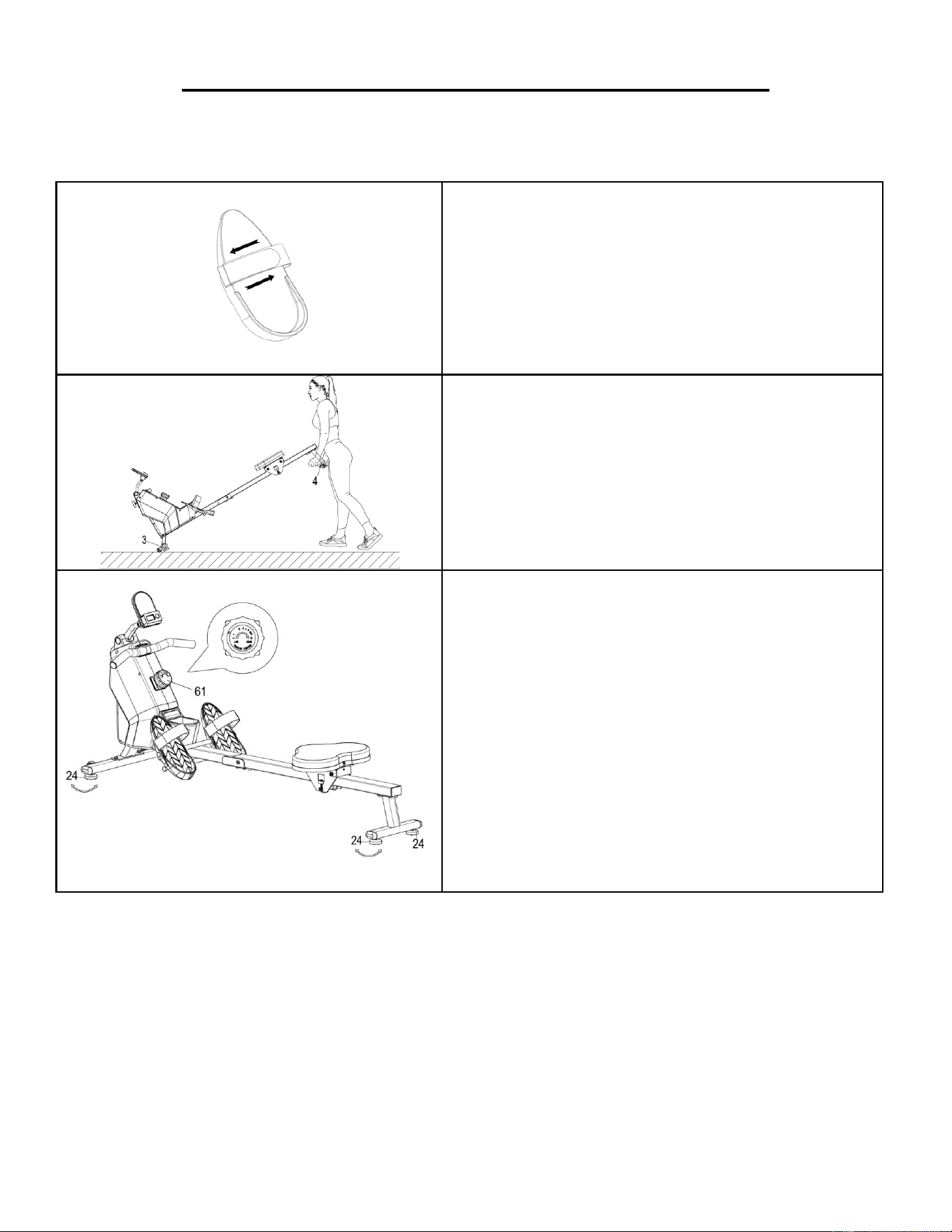
55
GUIDA ALLE REGOLAZIONI E ALL'USO
ATTENZIONE! Le parti mobili, come la seduta, possono provocare schiacciamenti e lesioni.
Tenere le mani lontane dalla guida di scorrimento durante l'uso!
REGOLAZIONE DELLE CINGHIE DEI PEDALI
Le cinghie dei pedali sono regolabili e possono
essere adattate alle dimensioni del piede
dell'utente.
NOTA: Per evitare lesioni, regolare le cinghie dei
pedali in base al piede dell'utente prima
dell'esercizio.
SPOSTAMENTO DEL VOGATORE
Per spostare il vogatore, sollevare lo
Stabilizzatore Posteriore (n. 4) finché le ruote di
trasporto dello Stabilizzatore Anteriore (n. 3) non
toccano il pavimento. Con le ruote di trasporto a
terra, è possibile trasportare il vogatore nel luogo
desiderato con facilità.
BILANCIAMENTO E REGOLAZIONE DELLA
RESISTENZA
Regolare i Piedini (n. 24) sul supporto posteriore
del vogatore se il vogatore è sbilanciato durante
l'uso.
Ruotare la Manopola di Controllo della Tensione
(n. 61) in senso orario per aumentare il livello di
resistenza. Ruotare la Manopola di Controllo
della Tensione (n. 61) in senso antiorario per
diminuire il livello di resistenza.
I livelli di tensione sono impostati dal livello 1, il più
basso, al livello 8, il più alto.
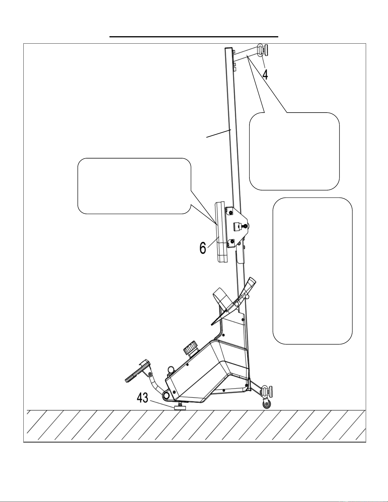
56
GUIDA ALLO STOCCAGGIO
ATTENZIONE!
Prestare attenzione quando
si posiziona verticalmente la
Guida di Scorrimento (n.
2) , poiché la testa potrebbe
toccare lo Stabilizzatore
Posteriore (n. 4).
Quando non viene
utilizzato, è possibile
risparmiare spazio
posizionando il vogatore
in posizione verticale sul
pavimento con Piedino
(n. 43).
SICUREZZA
NOTA: La Seduta (n. 6)
scivola verso il basso
quando si porta la Guida
di Scorrimento (n. 2) in
posizione verticale.
ATTENZIONE!
La Seduta (n. 6) scivola verso il basso
quando si porta la Guida di
Scorrimento (n. 2) in posizione
verticale.
2
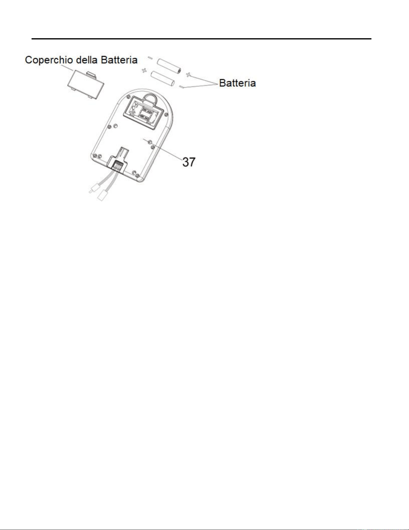
57
INSTALLAZIONE E SOSTITUZIONE DELLE BATTERIE
INSTALLAZIONE DELLE BATTERIE:
1. Estrarre 2 batterie AAA dall'alloggiamento del computer.
2. Premere il fermaglio del coperchio delle batterie sul retro del Computer (n. 37), quindi rimuovere il
coperchio delle batterie.
3. Installare 2 batterie AAA nell'apposito alloggiamento sul retro del Computer (n. 37). Prima
dell'installazione, prestare attenzione ai poli + e - della batteria.
4. Premere il fermaglio del coperchio delle batterie, quindi rimettere il coperchio delle batterie sul retro del
Computer (n. 37).
L'installazione è completa!
SOSTITUZIONE DELLE BATTERIE:
1. Premere il fermaglio del coperchio delle batterie sul retro del Computer (n. 37), quindi rimuovere il
coperchio delle batterie.
2. Rimuovere le 2 vecchie batterie AAA dal relativo alloggiamento e installare 2 nuove batterie AAA
nell'alloggiamento sul retro del Computer (n. 37). Prima dell'installazione, prestare attenzione ai poli + e -
della batteria.
3. Premere il fermaglio del coperchio delle batterie, quindi rimettere il coperchio delle batterie sul retro del
Computer (n. 37).
La sostituzione è completa!
NOTA: Sostituire sempre entrambe le batterie contemporaneamente. Non mischiare i tipi di batteria differenti
e non mischiare le batterie vecchie con le nuove. Smaltire le batterie secondo le linee guida nazionali e
regionali.
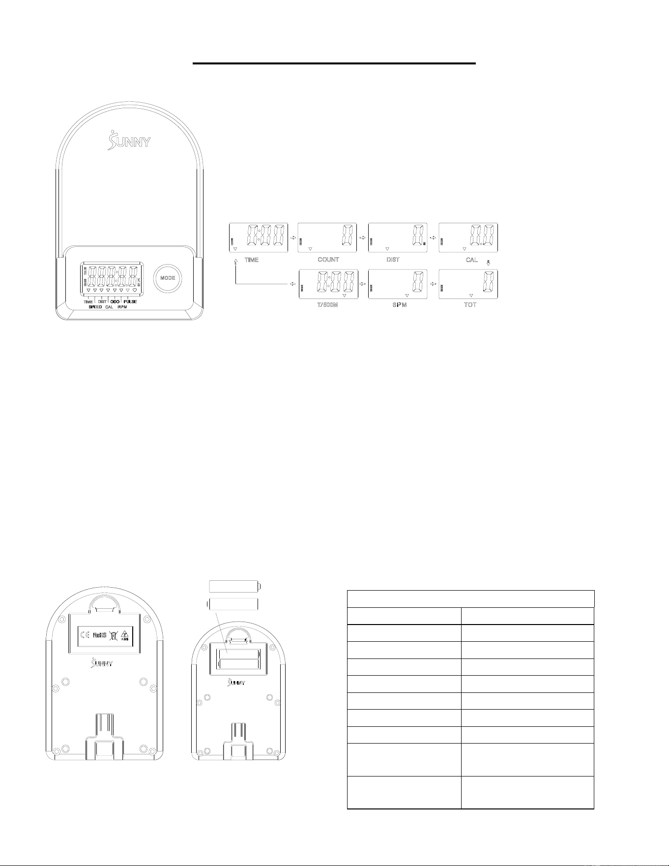
58
COMPUTER PER ESERCIZI
■FUNZIONI PRINCIPALI:
⚫ Premendo il tasto MODE si seleziona e si blocca una funzione per la sequenza seguente:
SCAN→TIME→ COUNT→ DIST→ CAL→ TOTAL COUNT (TOT) → SPM→T/500M →SCAN
⚫ Tenendo premuto il tasto MODE per 3 secondi si azzera il valore (senza TOT).
■MODALITÀ SLEEP:
⚫ Il sistema si accende quando viene premuto il tasto MODE e il sistema rileva un segnale in ingresso dal sensore.
⚫ Il sistema si spegne automaticamente quando il sensore non riceve alcun segnale in ingresso o non viene premuto alcun tasto
per circa 4 minuti.
■FUNZIONI:
⚫ SCAN: Il display cambia in base allo schema successivo ogni 6 secondi.
⚫ COUNT: Conteggio corrente dall'inizio dell'esercizio.
⚫ DIST: Distanza corrente dall'inizio dell'esercizio.
⚫ TIME: Tempi di lavoro totali trascorsi dall'inizio dell'esercizio.
⚫ TOTAL COUNT (TOT): Il conteggio totale dal primo inserimento delle batterie
⚫ CALORIES: Le calorie bruciate dall'inizio dell'esercizio.
⚫ SPM: Numero di vogate al minuto, indicante la velocità di vogata durante l'esercizio.
⚫ T/500M: Il tempo su 500 metri durante l'esercizio fisico
■ INSTALLAZIONE E SOSTITUZIONE DELLE BATTERIE
SPECIFICHE
SCAN
6S
TIME
999M:59S
COUNT
0~65535
DIST
0~65535 metri
TOT
0~65535
CALORIES
0.0~9999.9 Kcal
SPM
0~299
BATTERIA
DIMENSIONE AAA *2
Temperatura di
esercizio
0~40℃ (32℉-104℉)
Temperatura di
stoccaggio
-10~60℃ (14℉-140℉)

59
APP-VERBINDUNG:
SMART EQUIPMENT MIT DER SUNNYFIT APP VERBINDEN:
1. Scannen, um SunnyFit aus dem App-Store herunterzuladen:
2. Vergewissern Sie sich, dass die Bluetooth Funktion auf Ihrem mobilen Gerät eingeschaltet ist.
3. Wenn Sie die SunnyFit-App zum ersten Mal nutzen, folgen Sie den Anweisungen in der App,
um sich für Ihr kostenloses SunnyFit-Konto zu registrieren und anzumelden.
4. Starten Sie eine beliebige Trainingsaktivität, die zu Ihrem Smart-Gerät passt, und folgen Sie
dann den Anweisungen auf dem Bildschirm, um Ihr Smart-Gerät zu suchen und mit ihm zu
verbinden.
5. Wenn Sie verbunden sind, werden Ihre Statistiken und Rekorde am Ende des Kurses/der
Sitzung angezeigt und in Ihrem Kontoprofil gespeicher
FEHLERSUCHE:
•
Wenn Sie Probleme haben, Ihr Smart-Gerät zu verbinden, besuchen Sie
www.sunnyfit.com/guide oder scannen Sie den QR-Code unten:
•
Wenn Sie zusätzliche Unterstützung benötigen, wenden Sie sich bitte an

60
ELENCO PARTI
n.
Descrizione
Spec.
Qtà.
n.
Descrizione
Spec.
Qtà.
1
Telaio Principale
1
38
Bullone
M5*10
7
2
Guida di Scorrimento
1
39
Filo Sensore
L=310 mm
1
3
Stabilizzatore Anteriore
1
39A
Filo Sensore A
1
4
Stabilizzatore Posteriore
1
39B
Filo Sensore B
1
5
Impugnatura
Φ28*1.5
1
40
Bullone
Φ14*77.5*M8
1
6
Seduta
1
41
Manicotto Asse
2
7
Rondella
Ф8*Ф16*1.5
19
42
Rondella Grande
Φ8*Φ25*2,0
1
8
Rondella Elastica
Ф8
6
43
Piedino
M8*30*Φ52*19
1
9
Bullone
M8*20
10
44
Dado
M8*B4
2
10
Piastra di Supporto Seduta
2
45
Bullone
M6*55
1
11
Staffa a U
2
46
Anello Elastico Albero
2
12
Bullone
M8*100
3
47
Albero Puleggia Cinghia
1
13
Distanziale
Ф15*Ф8*4
6
48
Cuscinetto
6000
2
14
Cuscinetto
608
6
49
Puleggia Cinghia a Maglie
1
15
Ruota
3
50
Rondella
Φ6*Φ12*1.0
1
16
Tubo di Rivestimento per
Ruota Folle
3
51
Dado
M6
1
17
Dado
M8
6
52
Guida Impugnatura
1
18
Vite di Regolazione
M6*36
4
53
Tappo Terminale Rotondo
2
19
Tampone a U
4
54
Impugnatura in
Gommapiuma
Φ27*Φ33*214
2
20
Dado
M6 S10
4
55
Dado
M10*1.0*9
4
21
Bullone
M8*16
4
56
Dado
M10*1
4
22
Tappo Terminale
4
57
Set Completo Molla a
Spirale
1
23
Dado
M8
4
58
Cinghia a Maglie
1
24
Piedino
φ38*18-M8*25
4
59
Ruota Inerziale
1
25
Tappo Quadrato
1
60
Cinghia
220PJ
1
26
Tampone di Fine Corsa
Ф22*16
2
61
Manopola di Controllo
della Tensione
L=310 mm
1
27
Vite
M6*20
2
62
Rondella
Φ5
1
28
Bullone
M12*160
4
63
Bullone
M5*12
1
29L
Pedale Sinistro
1
64
Coperchio Sinistro
1
29R
Pedale Destro
1
65
Coperchio Destro
1
30
Cinghia Pedale
2
66
Portabottiglia
1
31
Bullone
M8*20 S6
2
67
Coperchio
2
32
Bullone
M8*40
2
68
Vite
ST4.2*20
6
33
Ruota di Trasporto
2
69
Vite
ST4.2*25
7
34
Tubo di Supporto per
Computer
1
70
Piastra di Spedizione
1
35
Bullone
M8*10
2
71
Vite
M8*10
2
36
Supporto Computer
1
72
Rondella di Plastica
Ф8*Ф20*2.0
2
37
Computer
1
73
Chiave a Brugola
S6
1
37A
Cavo Computer A
1
74
Chiave
S10,13,14,15
1
37B
Cavo Computer B
1
75
Chiave
S10,13,17,19
1
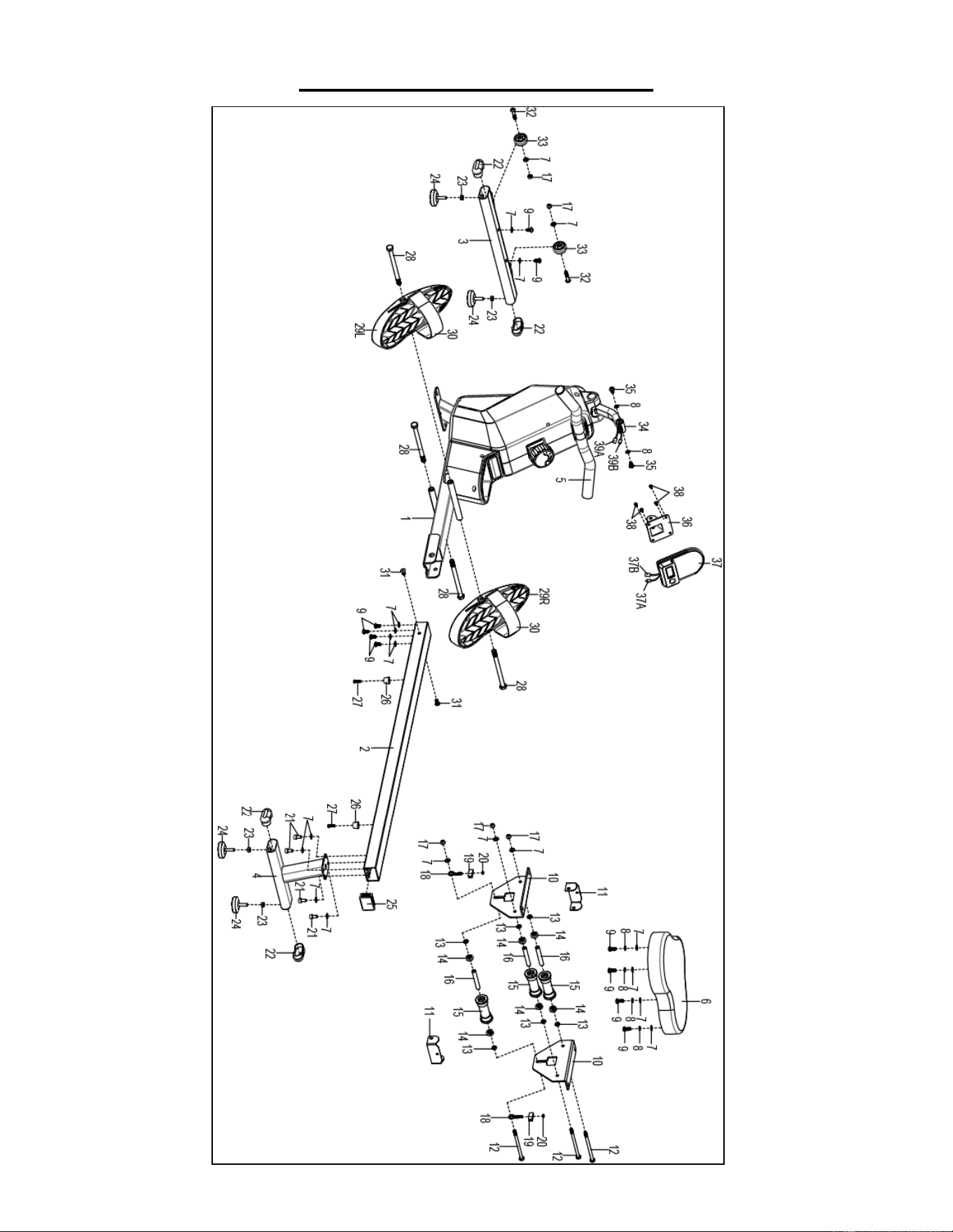
61
EXPLODED DIAGRAM 1
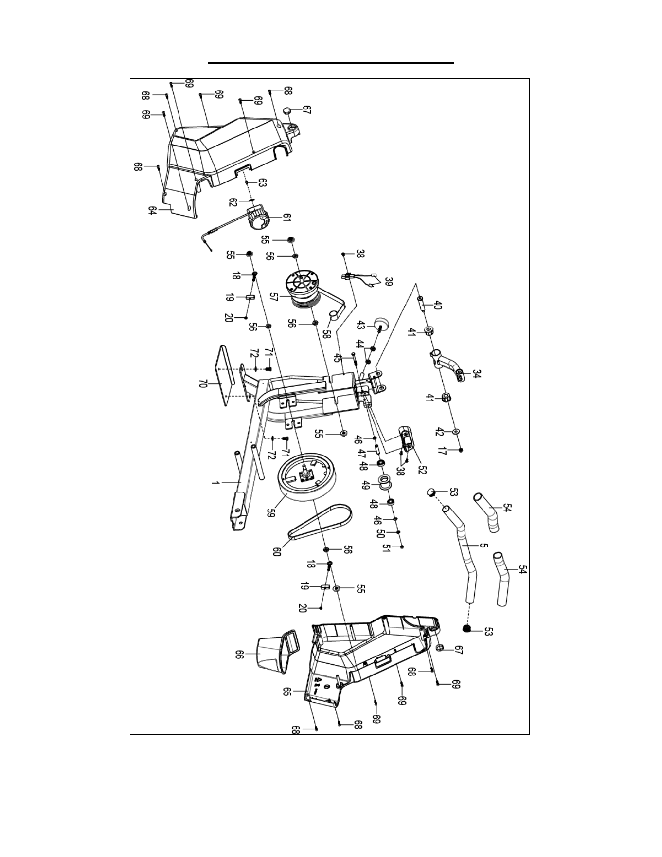
62
EXPLODED DIAGRAM 2
Version 3.4

63