
Loading ...
Loading ...
Loading ...
STEP 4: Reconnect Gas and Electrical Supply
Leak testing of the range shall be conducted according to the installation instructions provided with the range.
Before operating the range after the gas conversion, always check for leaks with a soapy water solution or
other acceptable method in at gas connections installed between the gas inlet pipe of the range, gas
regulator, and the manual shut-off valve.
WARNINGDO NOT use a flame to check for gas leakage.
STEP 5: Installation of New Rating Label
Record the model and serial number on the LP / Propane conversion label provided in this kit.
The information can be obtained from the existing Rating / Serial label. Place the LPG conversion label as
close as possible to the existing Rating / Serial label on the range.
Preparation
Before moving the range, protect any finished flooring and secure oven door(s) closed to prevent damage.
The oven door(s) can be removed to lighten the load or to fit the unit through a doorway. Only remove if
necessary. Do not remove the griddle or any other component. Door removal should only be done by a
certified installer or service technician.
21
Use soapy solutions to check for leakage on all joints.
Placement
Do not lift or carry the oven door by the door handle.
Use an appliance dolly to move the range near the opening. Remove and recycle packing materials. Do
not discard the anti-tip bracket supplied with the range.
Leveling
Raise the range to the desired height by adjusting the legs. The legs can be
adjusted by rotating the metal leg clockwise to raise and counter clockwise to lower.
IMPORTANT: Keep the injectors removed from the range for future use.
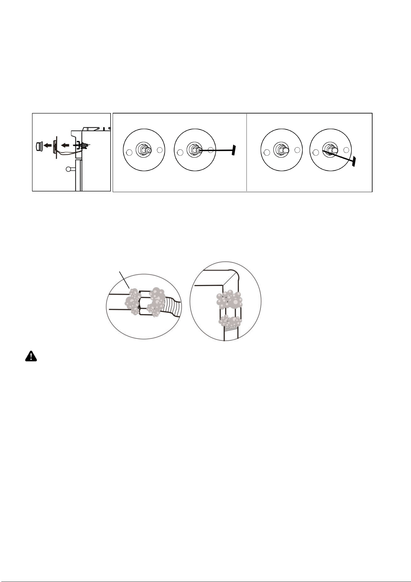
STEP 3: Gas Valve
a. Remove control knobs.
b. Using a flat screwdriver, adjust main burner bypass jets toward to 1/4 circle for LP until the flame
is normal.
For 9,000btu and 15,000btu burners, please refer to fig.1, which is in the center of valve
axis. For 20,000btu burners, please refer to fig.2, which is in the left side of valve axis.
fig.1
fig.2
Loading ...
Loading ...
Loading ...