INSTRUCTIONS
FOR INSTALLING AND USING
TEMPERATURE DIFFERENTIAL CONTROLLER
FOR SOLAR THERMAL SYSTEMS
ENG

INDEX
UTILISATION
Overview .......................................................................................................4
Product overview ............................................................................................ 4
Solar system overview .................................................................................... 6
Diagram ........................................................................................................... 8
Symbols and abbreviations lexicon .............................................................. 9
Commissioning and operations .................................................................16
Commissioning ................................................................................................ 16
Users settings .................................................................................................... 17
Setting access .............................................................................................. 17
Boost setting ................................................................................................. 17
Cylinder temperature setpoint .................................................................. 17
Operating modes ........................................................................................... 18
Test mode: manual testing of the installation .............................................. 19
Clock mode: time and off-peak hour setting ............................................. 19
Boost function.................................................................................................. 21
Safety functions ............................................................................................ 22
System cooling ................................................................................................ 22
Anti-freeze protection .................................................................................... 23
Protection of the cylinder against high temperatures ............................... 23
Anti-legionella protection ............................................................................. 23
Comfort functions ........................................................................................ 24
Solar pump control ......................................................................................... 24
Auxiliary heating control ................................................................................ 24
Storage priority ................................................................................................ 29
Heat quantity estimation .............................................................................. 29
Cold start feature ............................................................................................ 29
System state and display ............................................................................30
System information display ............................................................................ 30
Statistics ............................................................................................................ 32
Safety advice ...............................................................................................33
Proper usage ................................................................................................... 33
Dangers during installation and operations ................................................ 33
Detecting faults ............................................................................................... 33
Hot water temperature .................................................................................. 33
Exclusion of liability.......................................................................................... 33

INDEX
INSTALLATION
Mounting .......................................................................................................34
Wall installation................................................................................................ 34
Pump station installation ................................................................................ 35
Installation on a din rail .................................................................................. 35
Power supply and electrical connections ................................................ 36
Overview .......................................................................................................... 36
Fuse replace .................................................................................................... 39
Connections .................................................................................................... 39
Installer set .....................................................................................................46
Setting access ................................................................................................. 46
Select system ................................................................................................... 47
SYSTEM 01: Basic solar system with Electric auxiliary heating ..................... 48
SYSTEM 02: Basic solar system with Solar pump speed control (RPM)
and Electric auxiliary heating ....................................................................... 50
SYSTEM 03: Basic solar system with Hydraulic and Electric
auxiliary heating ............................................................................................. 53
SYSTEM 04: Solar system with Solar pump speed control,
Hydraulic Auxiliary and Electric auxiliary heating ....................................... 56
SYSTEM 05: Solar system with External Heat Exchanger and Electric
auxiliary heating ............................................................................................ 59
SYSTEM 06: Basic pool solar heating ............................................................. 62
SYSTEM 07: Pool solar heating with External heat Exchanger .................... 64
SYSTEM 08: Solar system with 2 DHW cylinders (or 2-layer cylinder),
3-way valve and Electric auxiliary heating ................................................. 66
SYSTEM 09: Solar system with 2 DHW cylinders (or 2-layer cylinder),
Second pump and Electric auxiliary heating ............................................. 69
SYSTEM 10: Solar system with Smart Hydraulic auxiliary from Solid
Fuel Boiler and Electric auxiliary heating ..................................................... 72
SYSTEM 11: Solar system with Heating Return Increase .............................. 75
SYSTEM 12: Solar system with EastWest collector Àelds (F1F2) and
Electric auxiliary heating .............................................................................. 79
SYSTEM 13: Solar system with 2-layer cylinder, 3-way Valve and
Electric auxiliary heating ............................................................................... 81
Troubleshooting ............................................................................................84
Product range and accessories ................................................................. 85
Legal guarantee ..........................................................................................85
7HFKQLFDOVSHFLÀFDWLRQV ..............................................................................86

OVERVIEW
PRODUCT OVERVIEW
Product plus points
- All in one product: 13 different systems (Dual Solar System East/West, swimming pool,
boiler).
- Auto max mode: Priority to comfort, all different energy sources available to guarantee the
desired sanitary warm water.
- Eco Mode: No more than the solar energy is used to minimize energy consumption.
- Boost Mode: guarantees occasional or daily preservation of the desired set temperature
during peak utilization hours of the sanitary hot water by the means of either the auxiliary
HOHFWULFKHDWLQJHOHPHQWRUWKHKRWZDWHUERLOHU7KHUHIRUH\RXZLOOEHQHÀWIURPDQDFFUXHG
comfort.
- Blue/red backlit large-scale display to distinguish installation and utilization.
- Clear and complete information, overview and ease of comprehension of the different
systems, simple access to (the) temperature measures.
- 3 secured access levels: wiring, installation, utilization.
- 3 mounting possibilities::DOO À[DWLRQLQVWDOODWLRQRQ',1UDLORU E\ÀWWLQJPRXQWLQJLQVRODU
pump station.
- Fast and easy connection without additional screws: simplicity and saving of time.
- Optimized kit: deliverable with or without temperature sensors.
Main functions
- Temperature difference switch.
- Pump speed control.
- Solar collector and cylinder protection against high temperature.
- Anti-freeze protection.
- Anti-legionella protection.
- Off-peak hour management from internal clock or external timeswitch.
- Statistics on output activity temperature and supplied solar heat (Info).
- Control of 1 or 2 cylinders, a 2-layer cylinder or a swimming pool.
- Management and optimization of auxiliary heating (electric or hydraulic).
- Heating boost, instant or daily-programmed.
(DVW:HVWFROOHFWRUÀHOGFRQÀJXUDWLRQ
SR IMH ENG LH V06 19 09 2013
4
Temperature differential controller for solar thermal systems.
:HWKDQN\RXIRUFRQÀGHQFHWKDW\RXJUDQWHGWRXVDQGZH
congratulate you to have chosen one of our products.
The solar controller is the result of extensive research into how
to make easy and simple for you to control a heating system
while respecting our environment.
OVERVIEW
Aperçu du boîtier
PRODUCT OVERVIEW
This manual describes only the installation, commissioning, operation, maintenance and
dismantling of the temperature differential controller for solar thermal energy systems. When
installing the remaining components, e.g. solar collectors, pump assemblies, storage units,
pumps and switching valves, be sure to observe the appropriate installation instructions
provided by each manufacturer.
5
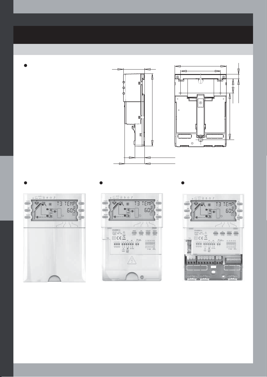
User interface Installer setting
interface
Installer wiring
interface
Dimensions
45 mm
20,5 mm
42,2 mm
154,5 mm
100 mm
30 mm
9,5 mm
110 mm
84 mm
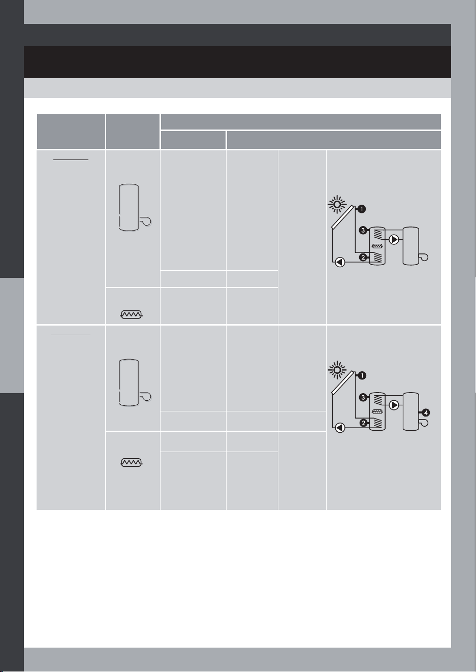
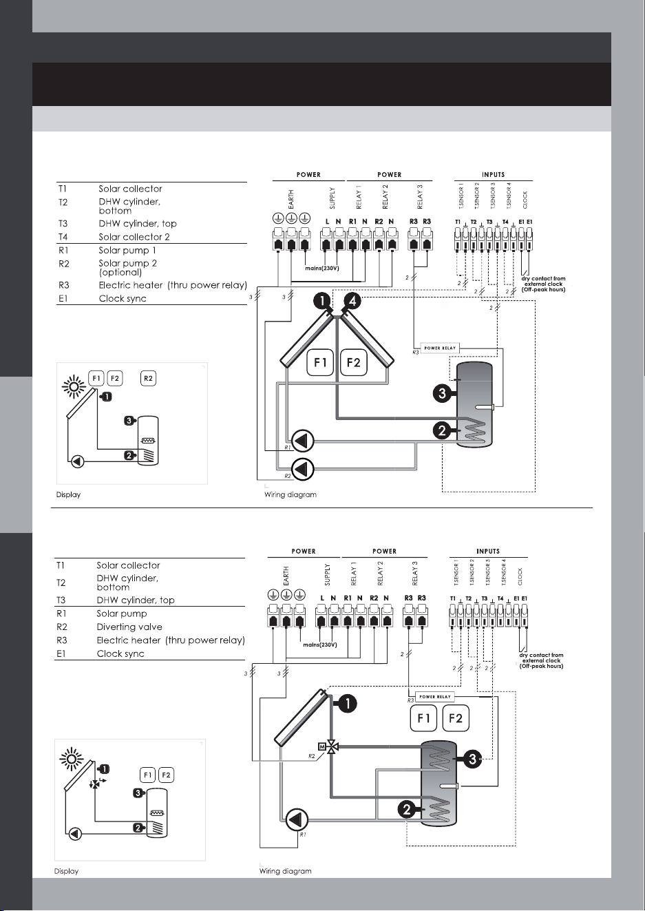
SOLAR SYSTEM OVERVIEW
OVERVIEW
System Diagram System Description
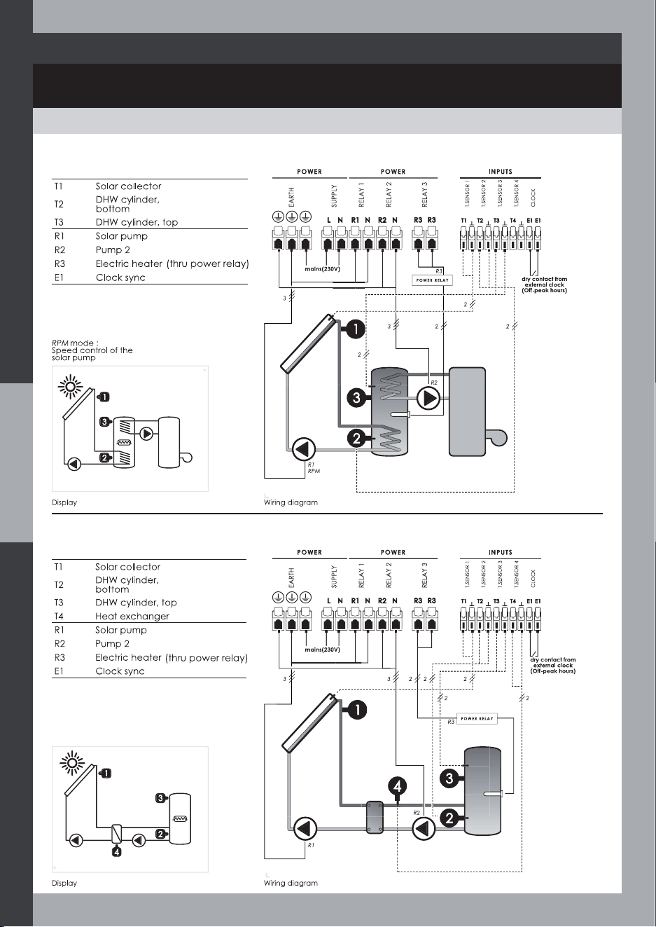
System 1 = SR
This system is intended for the control of a basic solar
water heater with electric auxiliary heating
System 2 = SRPC
This system is intended for the control of a basic solar
water heater with solar pump speed control (RPM) and
Electric auxiliary heating
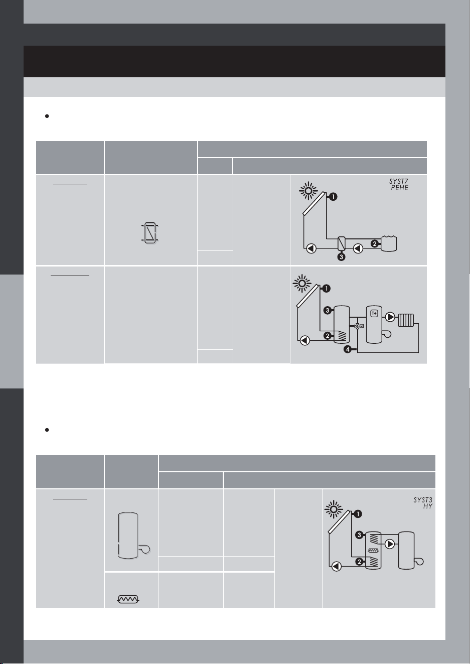
System 3 = HY
This system is intended for the control of a solar water
heater with both electric and hydraulic auxiliary
heating
SYST4
HYPC
System 4 = HYPC
This system is intended for the control of a solar water
heater with solar pump speed control (RPM) and both
electric and hydraulic auxiliary heating
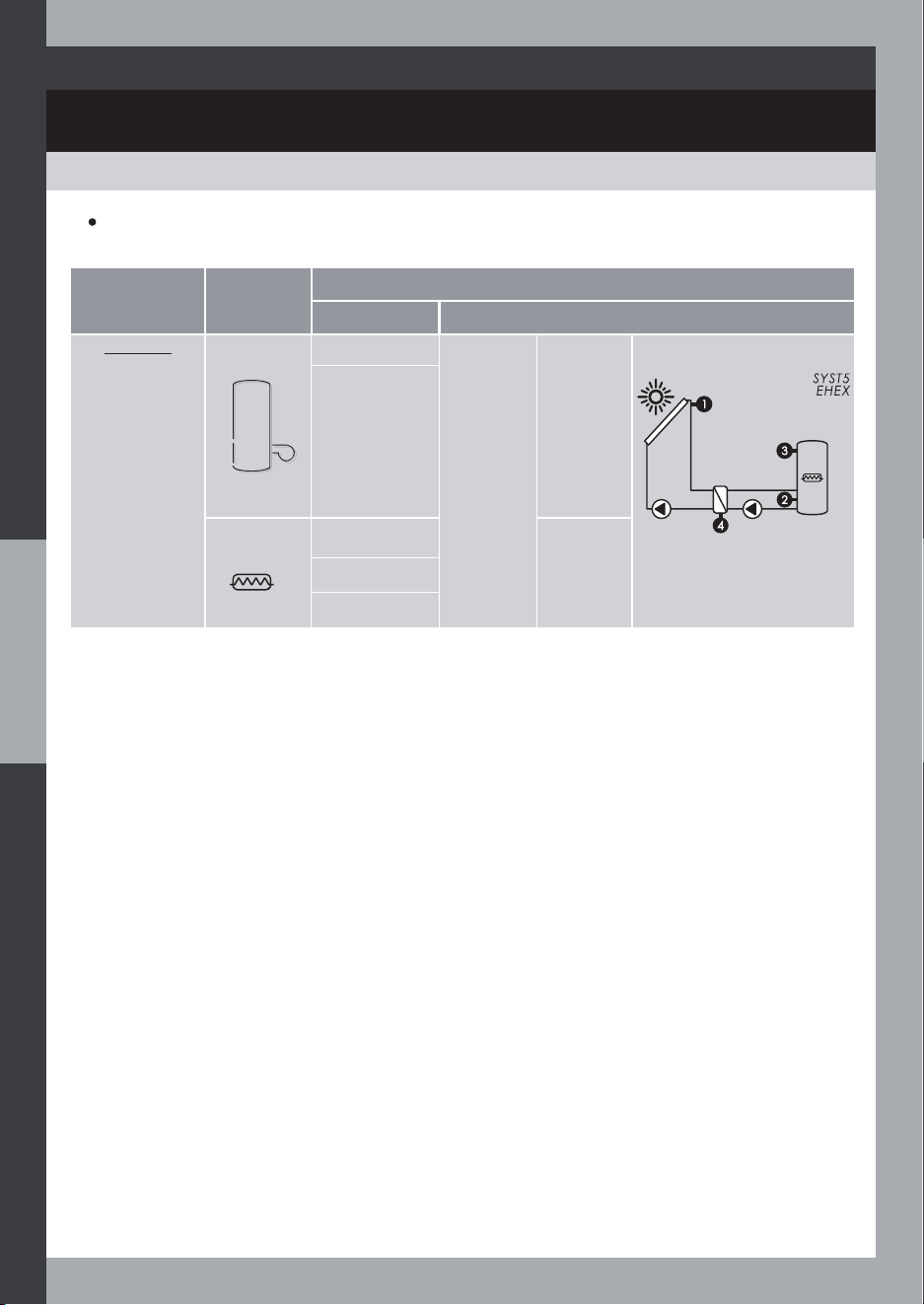
System 5 = EHEX
This system is intended for the control of a solar water
heater from an external heat exchanger
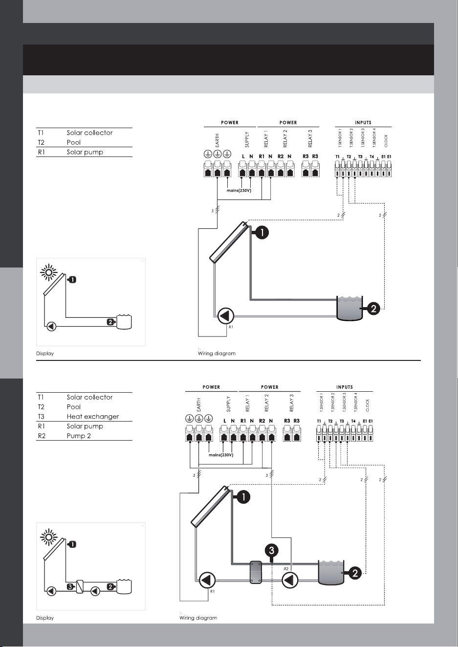
System 6 = POOL
This system is intended to control the solar heating of
a pool
System 7 = PEHE
This system is intended to control the solar heating of a
pool from an external heat exchanger
6
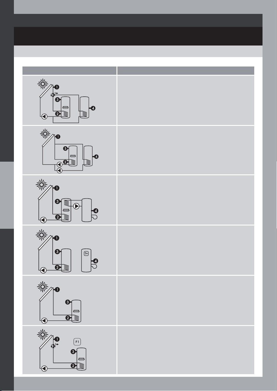
OVERVIEW
SOLAR SYSTEM OVERVIEW
System Diagram System Description
SYST8
2TKV
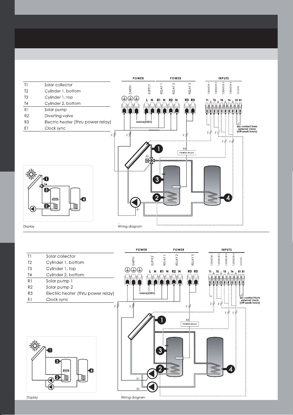
System 8 = 2TKV
This system is intended for the control of a dual-
cylinder solar water heater from a 3-way valve
R2 : 3-way valve
SYST9
2TKP
System 9 = 2TKP
This system is intended for the control of a dual-
cylinder solar water heater from two pumps
SYST10
HYSF
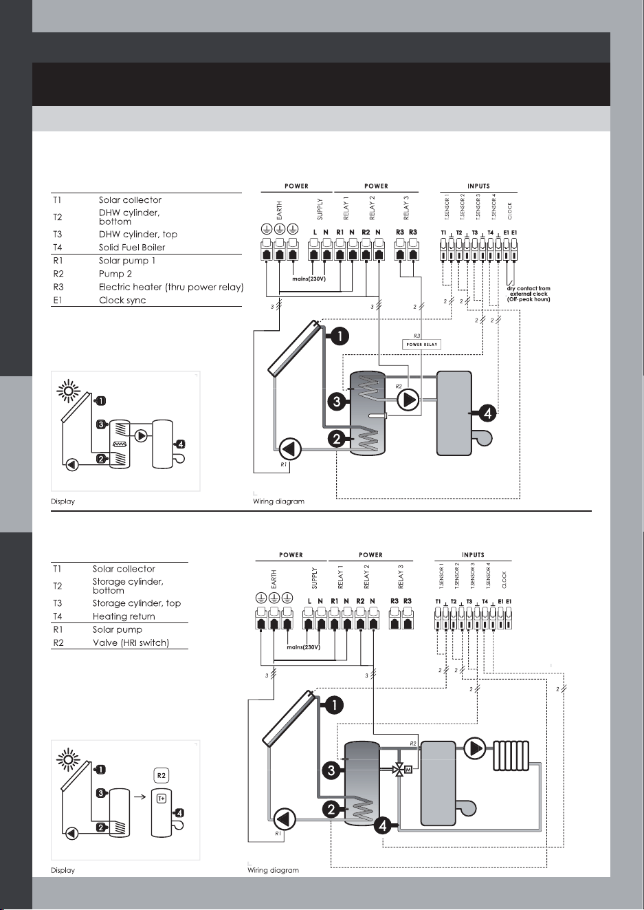
System 10 = HYSF
This system is intended for the smart control of a solar
water heater and a solid fuel boiler
SYST11
HRI
System 11 = HRI
This system is intended for the control of a central
Heating Return Increase
T4 : Heating Return
R2 : 3-way valve (HRI switch)
SYST12
E/W
System 12 = E/W
This system is intended for the control of a solar water
heater and East/West collector arrays (F1/F2)
T1 : Solar collector 1 (F1)
T4 : Solar collector 2 (F2)
R2 : Solar pump 2 (optional)
SYST13
2LV
System 13 = 2LV
This system is intended for the control of a solar water
heater and a 2-layer storage cylinder
R2 : 3-way valve
7
OVERVIEW
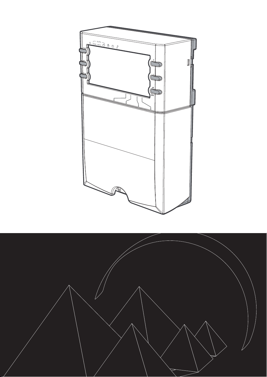
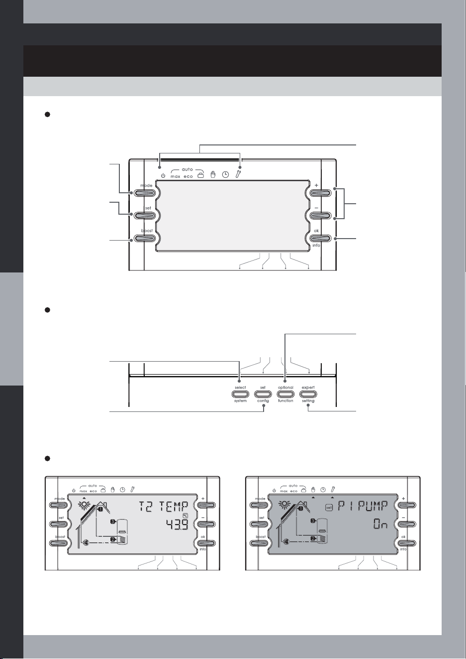
DIAGRAM
Installer Interface
Select system key
To select a system
number
6HWFRQÀJNH\
To set the
whole system
FRQÀJXUDWLRQ
Optional function
key
To set optional
functions
Expert setting key
To set expert
parameters
User interface
+/- keys
To change a
value or display
next parameter
Modes
Standby, Max,
Eco, Holidays,
Test, Clock and
Set
Mode key
Selecting
the mode
Set key
Setting
parameters
Boost key
Boost activation
ok/info key
To validate a
value / display
next setting
or display
information
8
Display and back-lit screen
Blue back-lit screen: user modes and
normal operating.
Red back-lit screen: installer modes and
faulty operating.
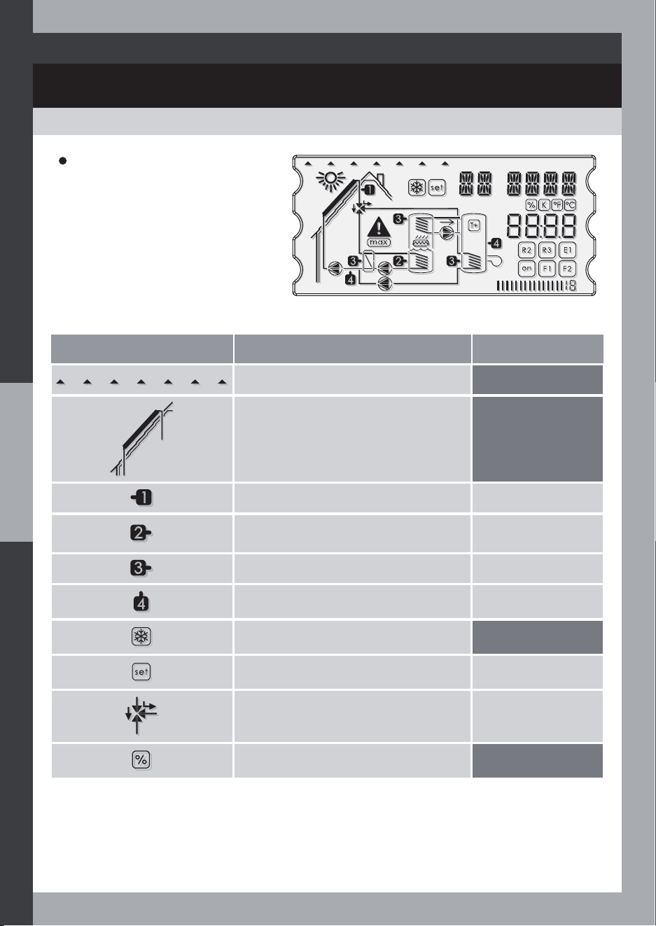
OVERVIEW
SYMBOLS AND ABBREVIATIONS LEXICON
Symbol Solid display Flashing display
Mode selectors
Solar collector
T1 sensor temperature (solar collector)
T1 sensor selection
T2 sensor temperature (lower section of
the cylinder or the pool)
T2 sensor selection
T3 sensor temperature
T3 sensor selection
T4 sensor temperature
T4 sensor selection
Anti-freeze function
Setting mode
Setting in progress
3-way valve
Valve selection
Rate per cent
9
Symbol
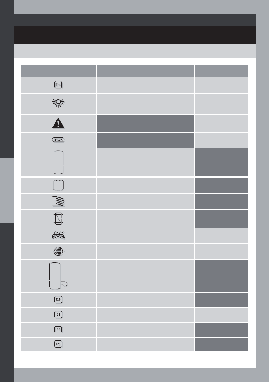
SYMBOLS AND ABBREVIATIONS LEXICON
OVERVIEW
Symbol Solid display Flashing display
Heat transfer to central heating (HRI
system)
Boost in progress
6XIÀFLHQWVRODUHQHUJ\ Delayed start or stop
of the solar pump
Error
Max. temperature
reached
Cylinder
Pool
Internal heat exchanger
External heat exchanger
Electric heater Electric heater
selection
Pump Pump selection
Boiler
R2 output
E1 input Off peak hours
running
Auxiliary function
Auxiliary function
10
OVERVIEW
SYMBOLS AND ABBREVIATIONS LEXICON
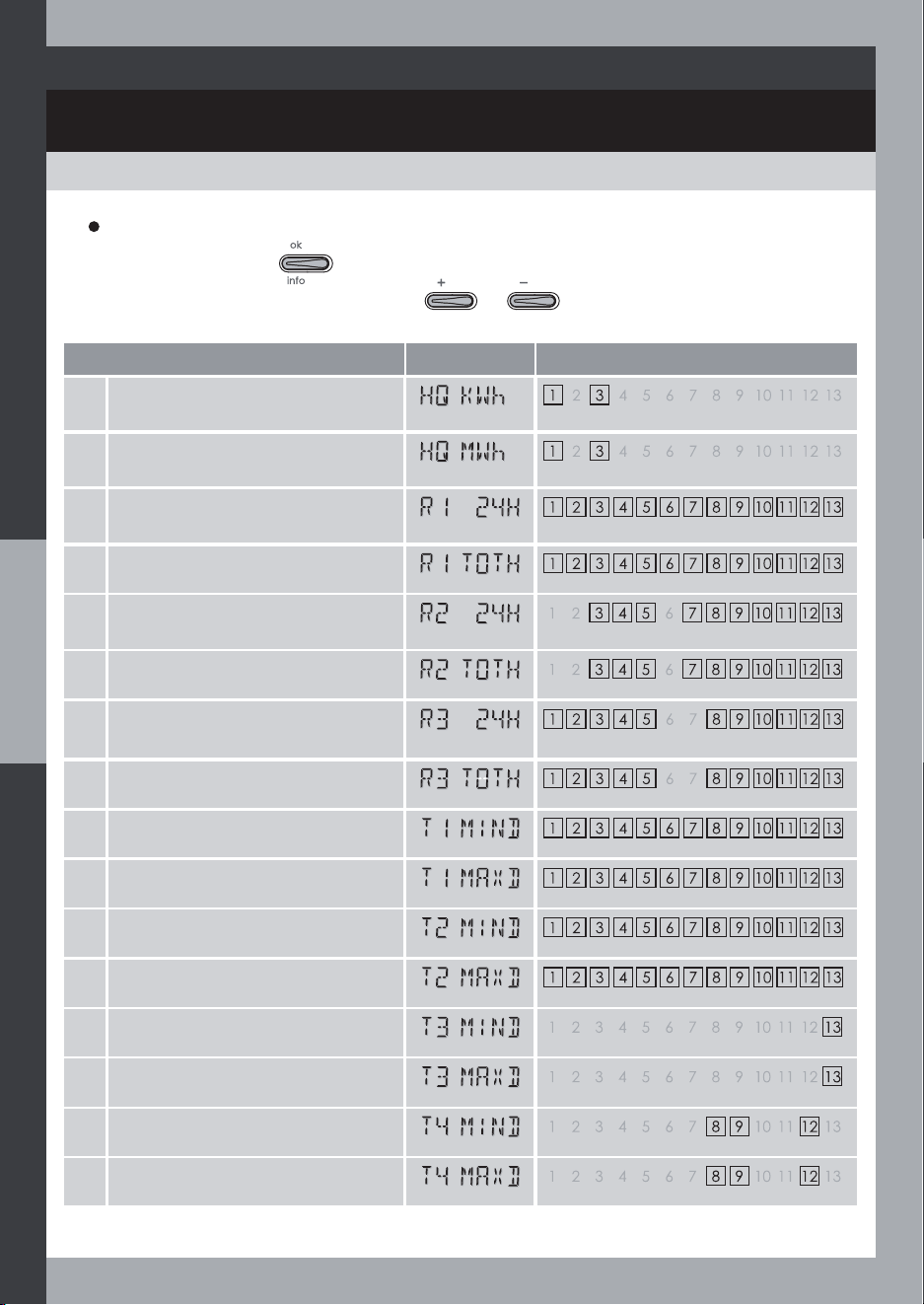
Abbreviations
Abbreviation
on display
Description
Boost
Boost cycle start (only daily Boost)
Boost cycle duration
User Mode
Standby mode
Clock Mode
Time
Low-tariff period
Low-tariff period start time
Low-tariff period stop time
Info and statistics
Supplied heat quantity estimation for the last 24 hours (KWh)
or in total (MWh)
R1 output on time count for the last 24 hours
R2 output on time count for the last 24 hours
R3 output on time count for the last 24 hours
R1 output on time count in total
R2 output on time count in total
R3 output on time count in total
T1 minimum temperature during the last 24 hours
T2 minimum temperature during the last 24 hours
T3 minimum temperature during the last 24 hours
T4 minimum temperature during the last 24 hours
T1 maximum temperature during the last 24 hours
T2 maximum temperature during the last 24 hours
T3 maximum temperature during the last 24 hours
T4 maximum temperature during the last 24 hours
11
OVERVIEW
SYMBOLS AND ABBREVIATIONS LEXICON
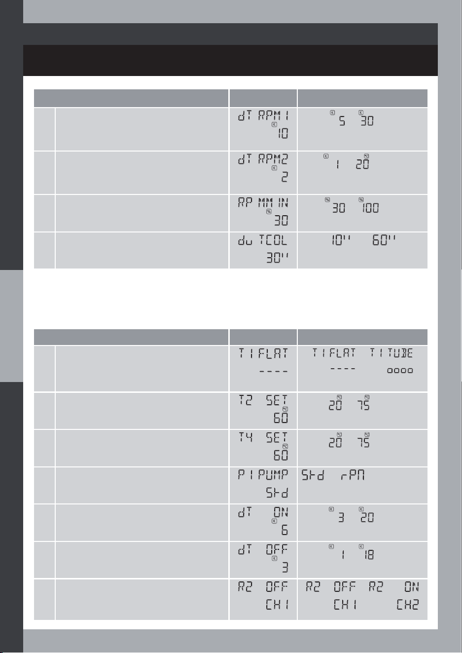
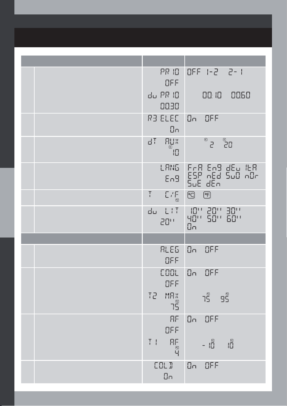
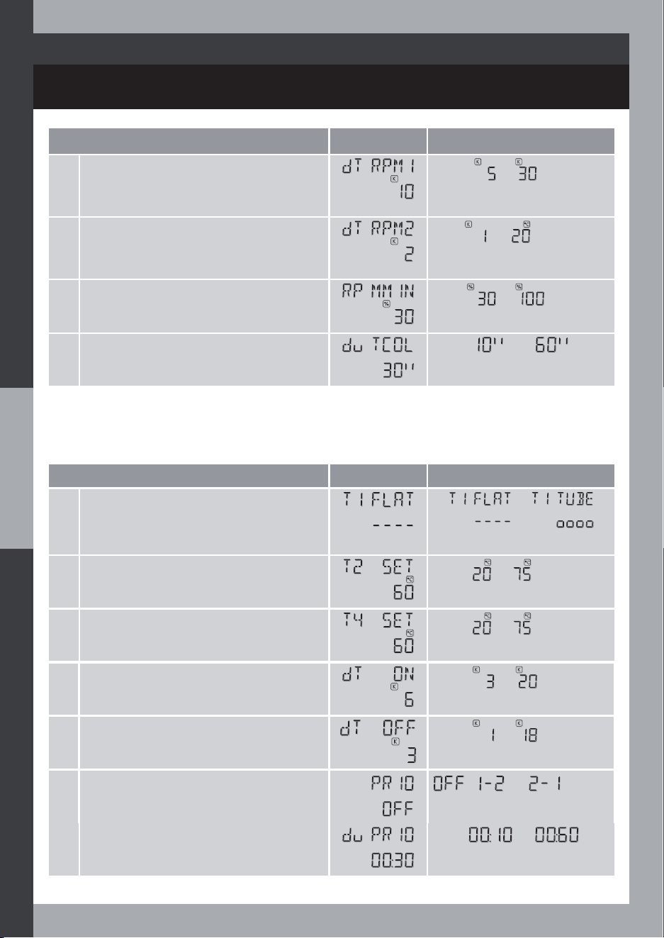
Select System
System SRPC = Number 2
ConÀg mode
1 or 2 pumps (with system 12)
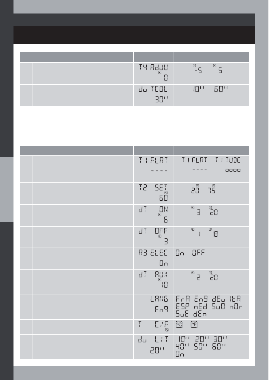
Flat collector type
Evacuated tube collector type
Temperature setpoint for storage cylinder
Temperature setpoint for second storage cylinder
Solar pump control (R1), ON/OFF mode
Solar pump control (R1), speed variation mode (RPM)
Storage cylinder loading priority order
Storage cylinder loading test period
Control of the electric heater
Control of the valve, CH1 valve way.
Control of the valve, CH2 valve way.
Temperature difference (from the temperature setpoint) for Auxiliary heating
authorization
Temperature difference to switch on the solar heating
Temperature difference to switch off the solar heating
T4 minimum temperature
12
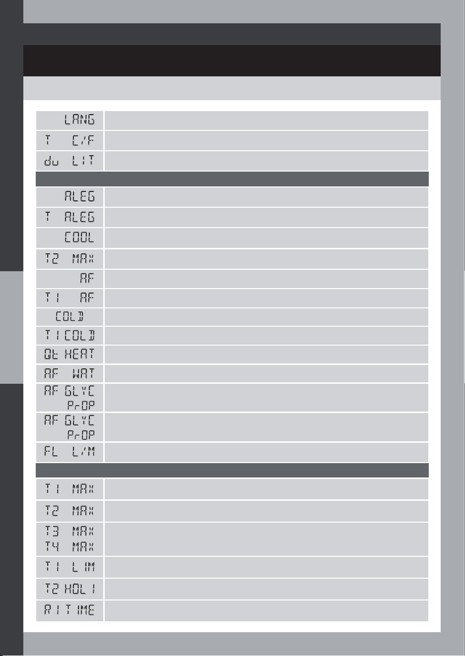
OVERVIEW
SYMBOLS AND ABBREVIATIONS LEXICON
Language selection
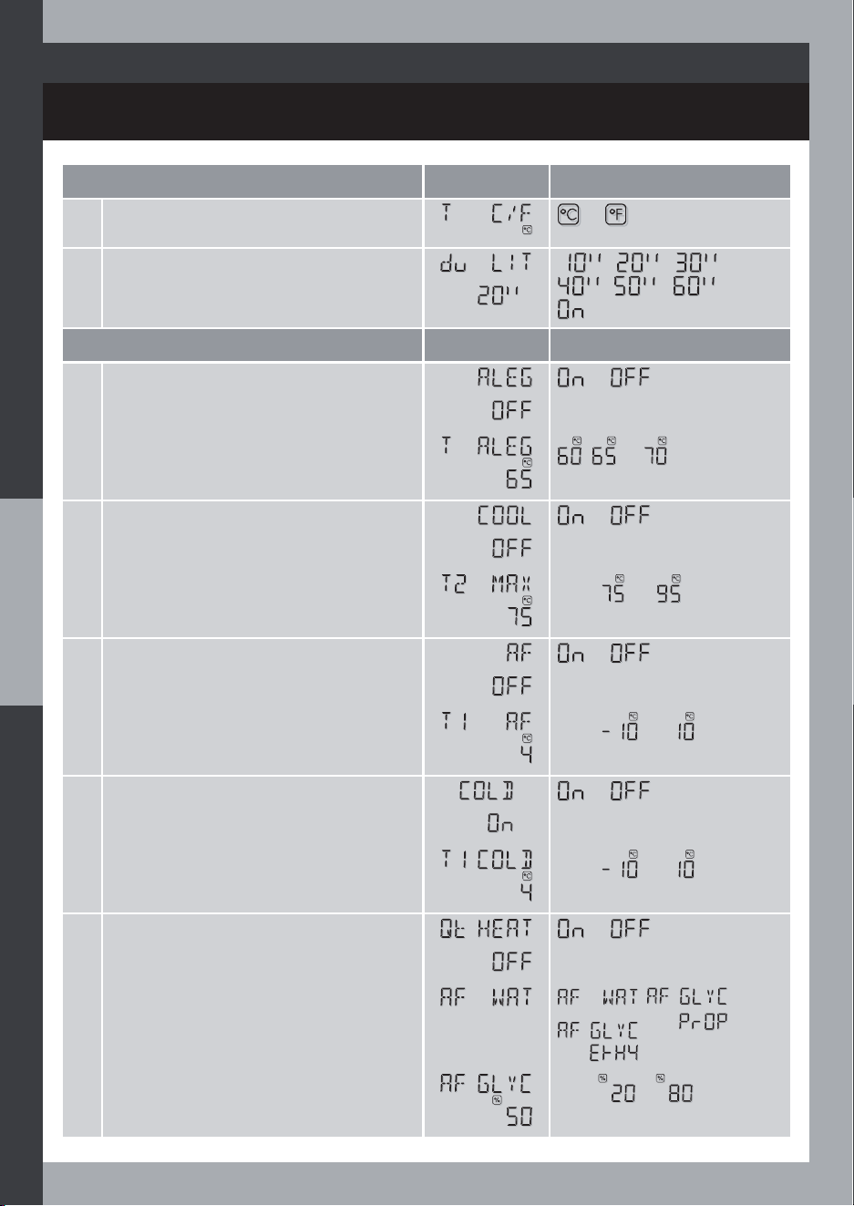
Degree unit selection
Display/light timeout
Functions mode
Anti-legionella function
Anti-legionella temperature setpoint
System cooling safety function
Cylinder temperature safety limit
Anti-Freeze function
Anti-Freeze temperature limit
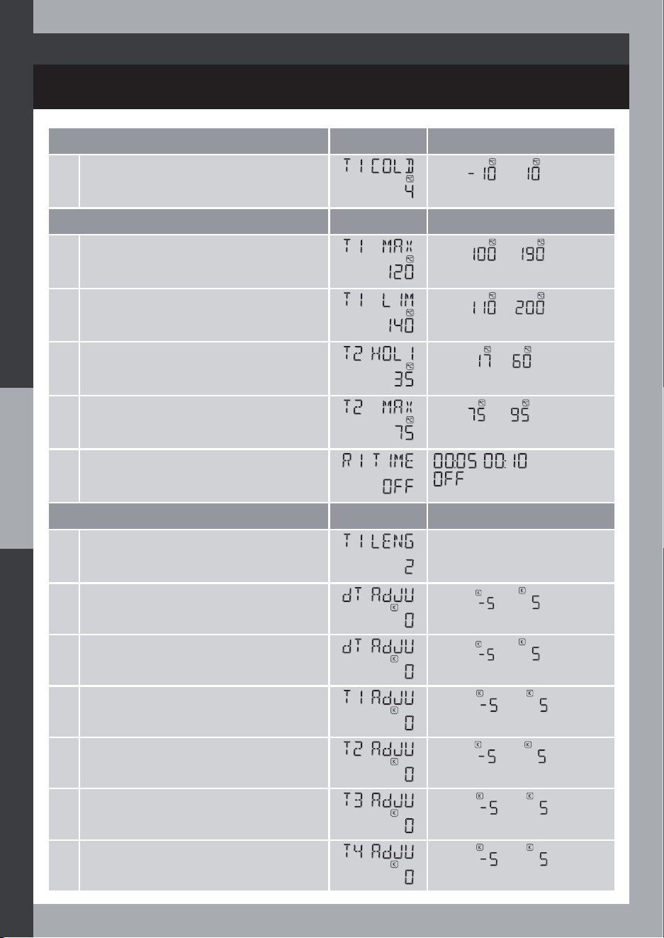
Cold start function
Cold start collector temperature limit
Heat quantity estimation function
$QWL)UHH]HÁXLGW\SHZDWHU
$QWL)UHH]HÁXLGW\SHSURS\OHQHJO\FRO
$QWL)UHH]HÁXLGW\SHHWK\OHQHJO\FRO
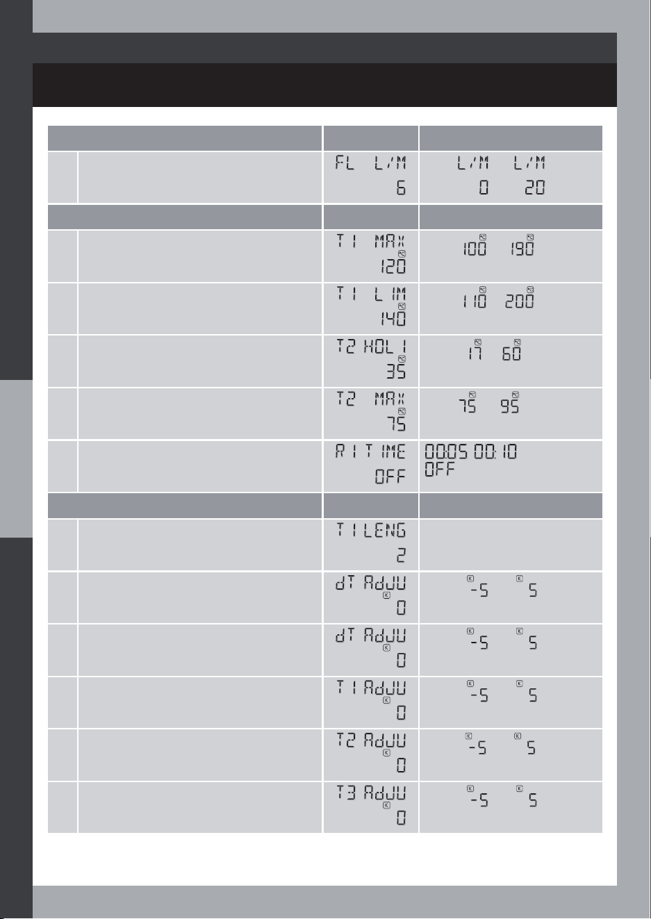
)ORZUDWHYDOXHUHDGRQWKHÁRZUDWHPHWHUWREHDVVLJQHGWRWKLVVHWWLQJ
Expert mode
Maximum collector temperature
Maximum cylinder temperature (safety limit)
Maximum exchanger output temperature
Collector temperature safety limit
Cylinder nominal temperature
Minimum pump-on duration
13
OVERVIEW
Expert plus mode
Length of the collector probe
Temperature difference zero adjustment value
T1 temperature zero adjustment value
T2 temperature zero adjustment value
T3 temperature zero adjustment value
T4 temperature zero adjustment value
Nominal temperature difference for pump speed control
Unit temperature difference for pump speed control
Minimum pump speed ratio
Tube collector temperature test duration
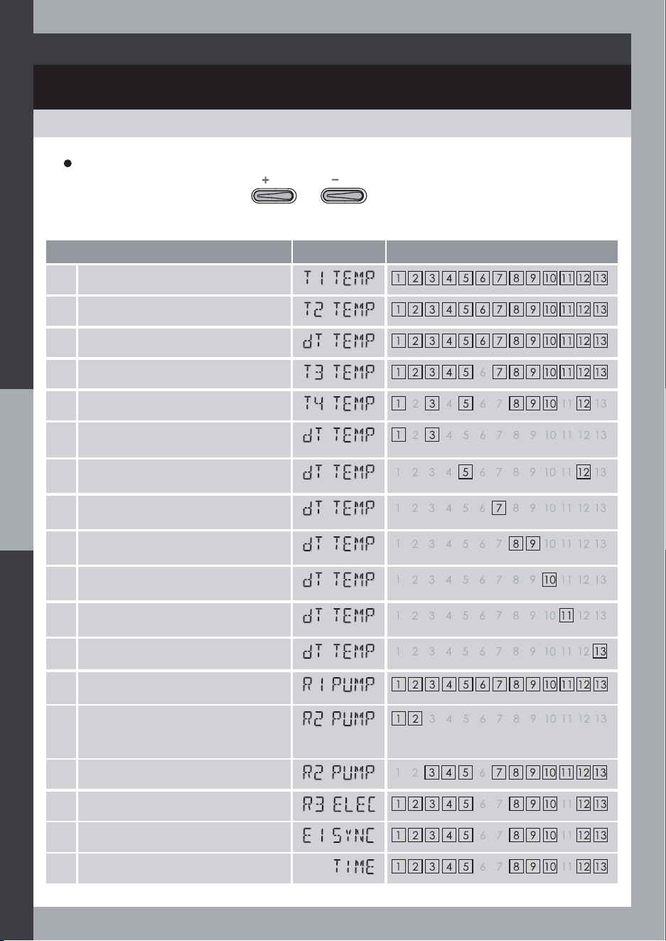
System information display
T1 Temperature
T2 Temperature
T3 Temperature
T4 Temperature
R1 output to solar pump
R2 output to auxiliary pump
R3 output to electric heating control
Measured temperature difference
E1 input contact (off-peak hour synchronization)
Time
Auto-diagnostic
Protection against High temperature running (at T1)
Anti-Freeze function running (at T1)
SYMBOLS AND ABBREVIATIONS LEXICON
14
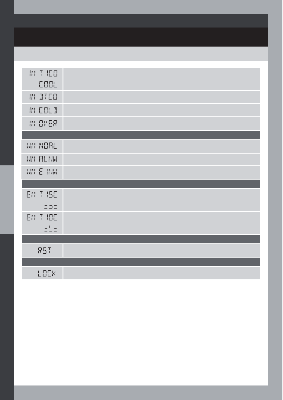
OVERVIEW
SYMBOLS AND ABBREVIATIONS LEXICON
Cooling running at T1
DTCO delay running
Cold start function running
Pump overrun function running
Warning messages
AL cannot run because no auxiliary heating enabled
AL Not Working properly
E1 Not Working properly
Errors
Short-circuit at T1 preventing the system from working
Open-circuit at T1 preventing the system from working
Reset
Restore factory settings
Setting lock
Keys locked
15
COMMISSIONING AND OPERATIONS
COMMISSIONING
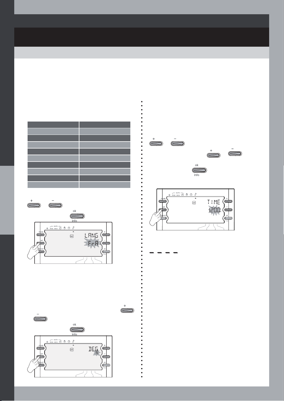
1- Setting the language
One of 10 languages may be selected:
French English
FRA ENG
German Italian
DEU ITA
Spanish Dutch
ESP NED
Finnish Norwegian
SUO NOR
Swedish Danish
SUE DEN
2- Setting the measure unit of the
temperature
You can select Celsius or Fahrenheit
degrees:
4- Select system
Select the system matching your actual
installation.
See installer settings section (page 42).
$WWKHÀUVWSRZHURQ
1- Select the language.
2- Set the time.
3- Select the system.
Select the desired language using
or .
Save by pressing
.
Select the desired measure unit using
or .
Save by pressing
.
3- Setting the time
The internal off-peak hours and
programmable Boost functions require the
time to be set.
7KHWLPHGLVSOD\ÁDVKHVVHWWKHWLPHXVLQJ
or .
Hold down the button
or to
scroll through faster.
Save by pressing
.
Note : You can move on from the settings
once the area shown as four underlines
has been set as a time.
16
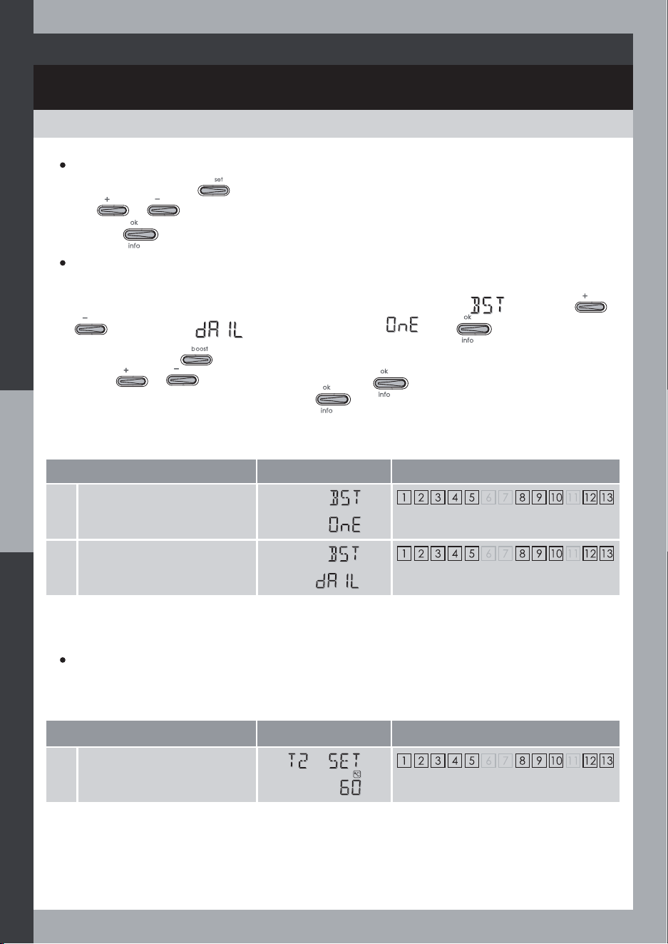
USERS SETTINGS
COMMISSIONING AND OPERATIONS
Boost setting
Display Related systems
1 One-shot Boost
2 Daily boost
The boost function is factory set ‘one –shot’ i.e. heating once at mode run.
You can change this to a programmed ‘daily boost’, the screen shows
by pressing
or
and setting to (daily boost) instead of . Press to save.
Then if you press the
button. You will be asked the time the daily boost shall start (set the
time with or ), save the setting by pressing , then the boost heating duration.
Set a value of 1 or up to 9 hours, then press
.
Consult the table on page 24 to see what type of auxillary heating method can be used by the
controller to heat the hot water during this boost period.
Note: For more details concerning the boost function, please refer to paragraph Boost start
page 21.
Setting access
Select the type of Boost
Cylinder temperature setpoint
Temperature setpoint
Display Related systems
1 Cylinder temperature
setpoint
The cylinder temperature setpoint is preset at 60°C. You can set the temperature between 20°C
and 75°C, by 1°C step.
From Auto mode, press
to access user settings.
Using
or you can change the parameter
Save it by
.
17
OPERATING MODES
COMMISSIONING AND OPERATIONS
Select the required mode by pressing once or several time.
Mode sequence:
Standby Mode
Max Mode
(automatic)
Eco Mode
(automatic)
Holidays Mode
(automatic)
Test
Mode
Clock
Mode
Standby Mode
This mode disables the water heating , in
summer for instance.
All functions are disabled except primary
system protection functions (protection
against high temperature, AF) and Boost.
Max Mode (automatic)
The controller operates automatically
according to the settings.
Maximal comfort, solar heating with
hydraulic or electric auxiliary heating
(depending on the selected system).
Eco Mode (automatic)
Ecological / Economy Automatic mode
without any auxiliary heating except
for Boost function or Anti-Legionella
protection.
Clock setting Mode
Mode to change the time and time-related
settings.
Holidays Mode (automatic)
This feature allows the cooling of the hot
water storage cylinder at night to reduce
stagnation times during the following day
when the system is not being used (holiday
periods for example). This is most effective
ZLWKÁDWSODWHFROOHFWRUV7KHFRROLQJRIWKH
cylinder at night (by running the R1 solar
pump) is controlled to achieve a pre-set
temperature (T2 HOLI, settable in EXPERT
mode, for example 35°C). Consideration
should be given to preserving a potential
in the cylinder for capacity to ‘cool’ the
system i.e. the collector during the day
should the safety feature for cooling the
system be required.
Manual test mode
Manual test mode for the installer to drive
manually the outputs during the system
setup.
18
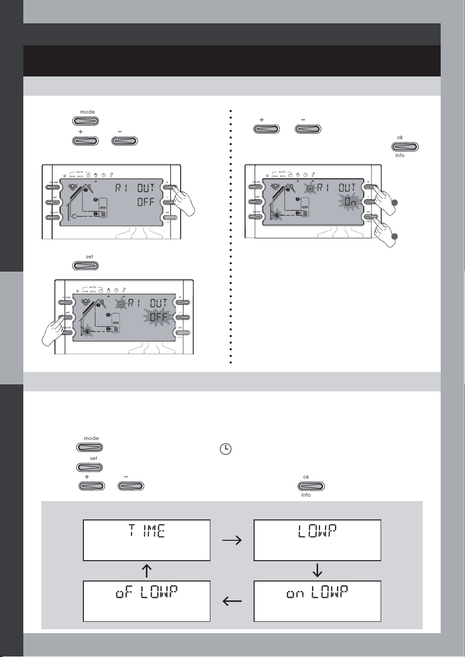
TEST MODE: MANUAL TESTING OF THE INSTALLATION
COMMISSIONING AND OPERATIONS
CLOCK MODE: TIME AND OFF-PEAK HOUR SETTING
19
3- Press to modify the output state.
1- Press to select the Test mode.
2- Press
or to select the
output you want to force for testing.
4- You can change the output state by using
or .
Go to the next output by pressing
.
1
2
For more energy savings, this function enables you to program an off-peak hour time range.
The electric auxiliary heating will be allowed in off peak-hour only (this function can be used
in Auto Max mode only).
1- Press to set the mode selector on .
2- Press to enter the setting.
3- Press
or to change the parameter value and to save it.
Time setting
Internal Low-tariff period
setting enable
Off-peak Period end Off-peak Period start
Parameter sequence:
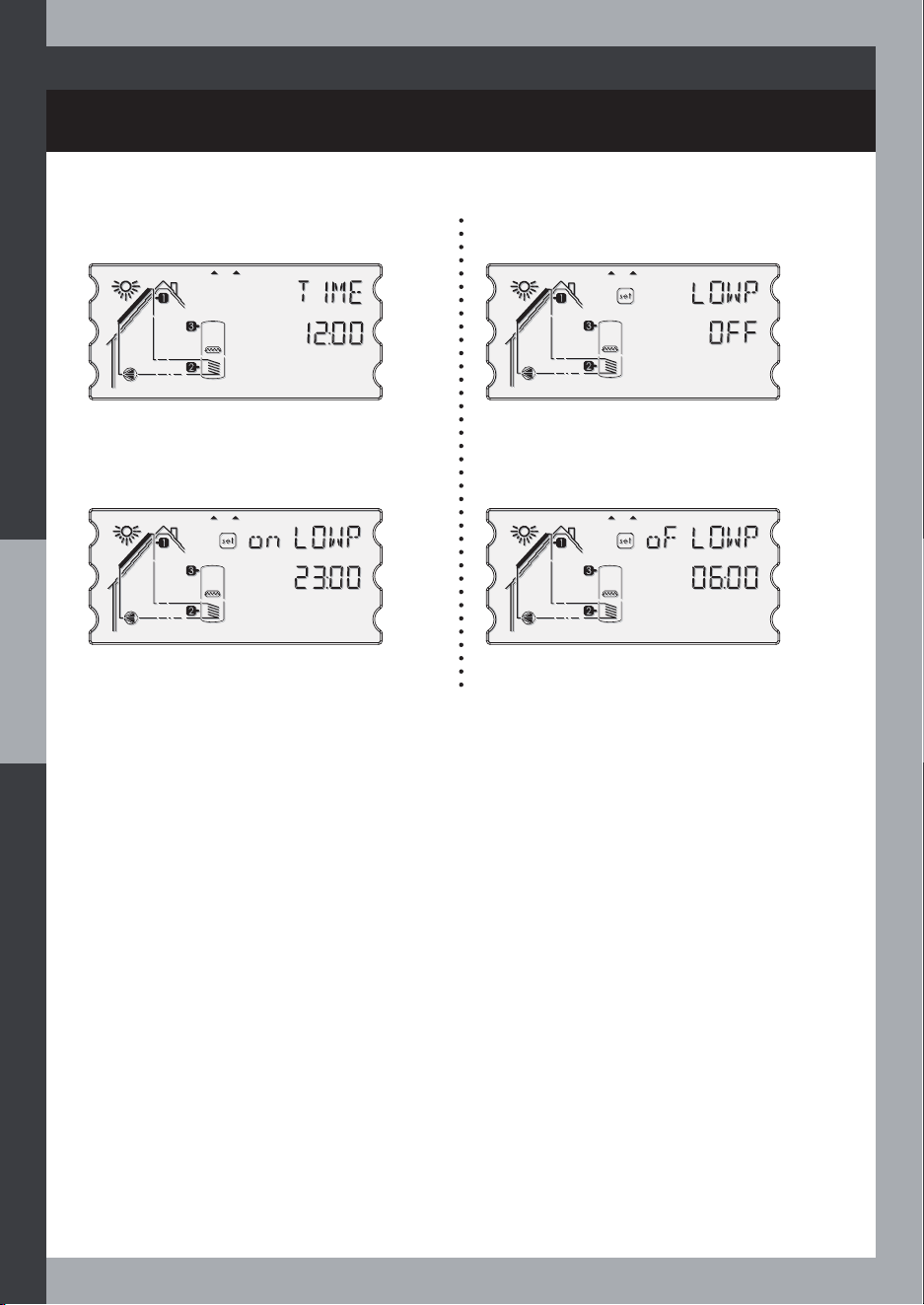
COMMISSIONING AND OPERATIONS
20
Time setting Internal Low-tariff period setting
enable
Off-peak Period start Off-peak Period end
Priority between programmed off-peak times (LOWP) and off-peak times determined by the
contact (E1SYNC) connected to an external clock “Ext clock”:
- A time is deemed to be “off-peak” by the system:
If the circuit connecting the two “Ext clock” input terminals is closed (E1SYNC), this is the
external off-peak time state, OFPE, or in programmed off-peak time (LOWP), it is the internal
off-peak time state, OFPI.
- The external input always overrides the internal programming (OFPI). The programmed off-
peak times (OFPE) are cancelled as soon as the circuit connecting the two “Ext clock” input
terminals is closed.
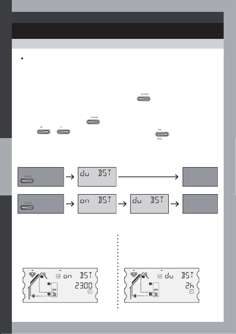
BOOST FUNCTION
COMMISSIONING AND OPERATIONS
Boost start
From Auto Max mode or Auto Eco mode, Boost function is used to guarantee that the hot
ZDWHUZLOOEHDWWKHWHPSHUDWXUHGHVLUHGE\WKHXVHUHYHQZKHQWKHVRODUKHDWLQJLVLQVXIÀFLHQW
Boost function can be used only if you set up an electric heater or a hydraulic auxiliary heating
from a boiler.
2 types of Boost :
- One shot: Manual Boost activation by pressing
.
- Daily Boost: Automatic Boost activation each day of the week at the pre-set time once
programmed.
1- Start Boost mode by pressing
.
2- Press
or to change the Boost timing and save by .
Setting the daily Boost time start
Set the time between 00:00 and 23:30 by 30
minutes step.
The time is preset at 23:00.
Setting the Boost duration
Set the duration between 1h to 9h by 1h
step.
The duration is preset at 2h.
Parameter sequence:
One-shot Boost
One-shot
Boost cycle
started
Boost duration
Daily Boost
Daily Boost
programmed
Boost start time Boost duration
21
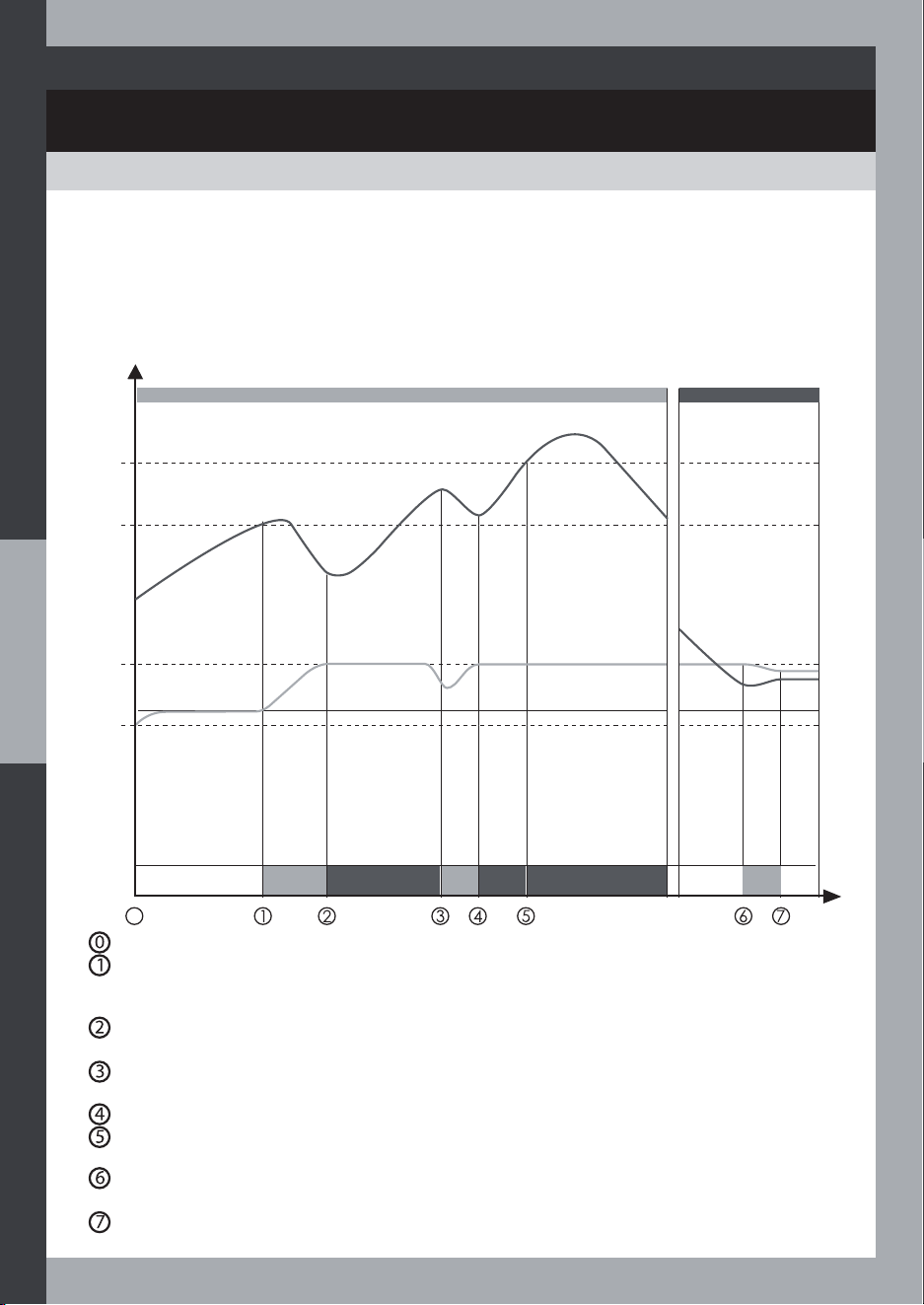
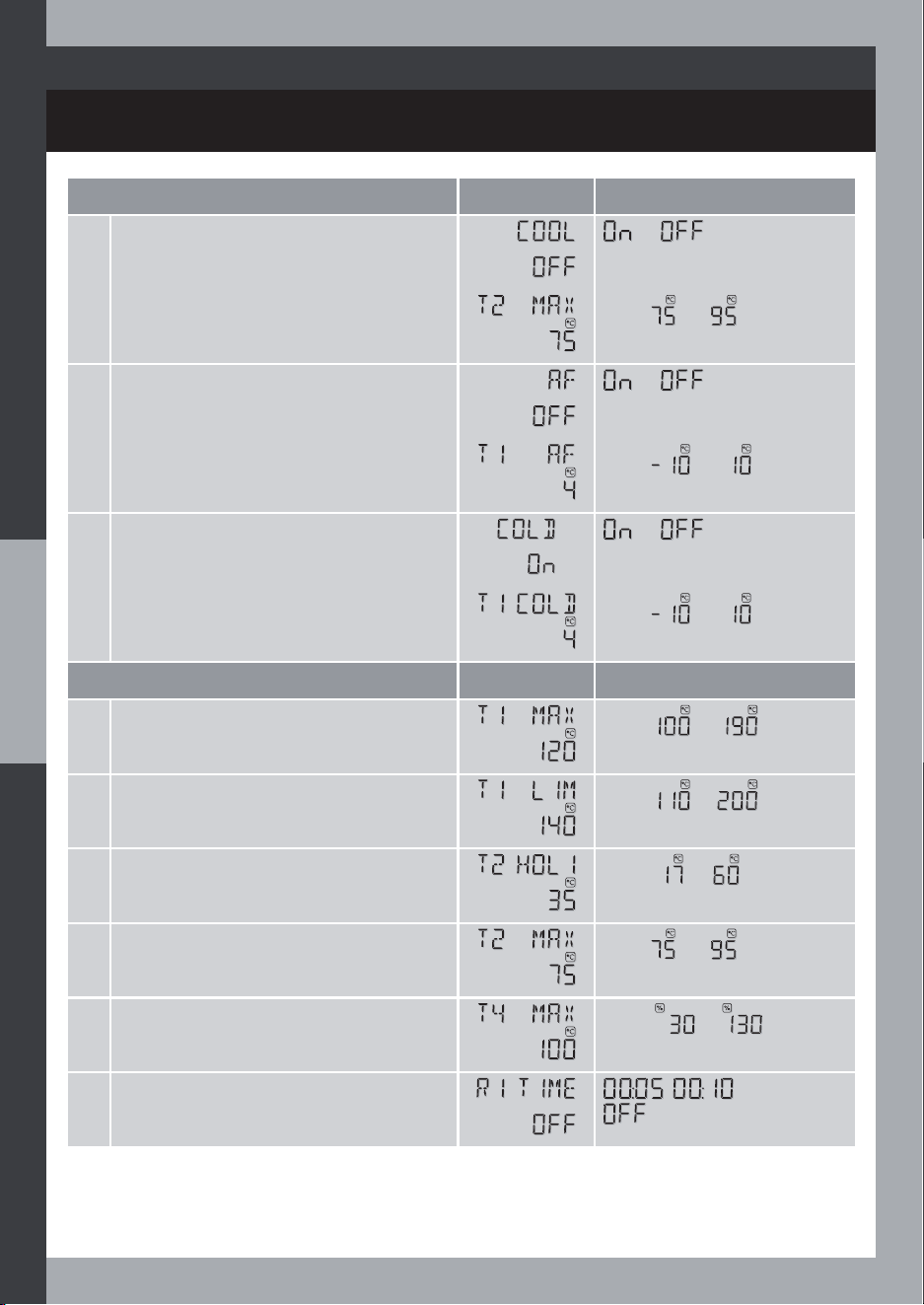
SAFETY FUNCTIONS
SYSTEM COOLING
If the system cooling function is not activated (default), the solar pump is stopped once the
collector temperature (T1) reaches T1 MAX.
If the System cooling function is activated (COOL ON in the « Optional function » mode), the
solar pump will run as soon as the collector temperature reaches T1 MAX (set in the « Expert
setting » mode) in order to cool down the collector with the colder cylinder water as long as
the temperature in the cylinder does not reach T2 MAX safety limit also set in the Optional
function mode.
T2 is about to reach T2 SET temperature setpoint.
T1 reaches T1 MAX temperature limit, the solar pump starts running to cool down and
protect the collector (this will warm up the cylinder which is allowed up to T2 MAX
temperature security limit).
T2 has attained T2 MAX, the solar pump is not allowed anymore to run in order to prevent
overheating inside the cylinder.
Some hot water is drawn from the water cylinder, T2 decreases, the pump can run again
in order to cool the collector.
T2 increases to T2 MAX, again, the solar pump stops in order to protect the cylinder.
T1 exceeds T1 LIM, the controller cannot stop this progression, the expansion vessel
represents the very last protection for the collector.
At night, T1 drop below T2 (the switch-on threshold is T2-dTON), the pump runs to cool the
cylinder since T2 is above T2 SET.
T2-T1 temperature difference decreases down to dTOFF switch-off threshold, the pump
stops, etc...
0
60
T2 SET
T2 MAX
COLLECTOR
COOLING
NORMAL
OPERATION
NORMAL
OPERATION
COLL.
COOL
CYLINDER
PROTECTION
CYLINDER
PROTECTION
75
T1 LIM
T1 MAX
T1
T2
T1
T2
Temperature
SUMMER DAY COOLING SCENARIO
Time
0
DAY NIGHT
CYL.
COOL
NORM
OP.
22

SAFETY FUNCTIONS
ANTI-FREEZE PROTECTION
If the Anti-freeze protection (AF) function is activated, the solar circuit pump is switched on as
soon as the collector temperature sinks below +4°C (adjustable limit). This causes heat to be
pumped through the collector from the lower part of the storage cylinder in an attempt to
prevent the collector from freezing.
If the collector reaches a temperature of +7°C, the pump is switched off again.
7KLVIXQFWLRQLVXVHOHVVLIDJO\FROEDVHG$)WUDQVIHUÁXLGXVHG
Activating the frost protection function
See installer settings section.
ANTI-LEGIONELLA PROTECTION
PROTECTION OF THE CYLINDER AGAINST HIGH TEMPERATURES
The Anti-Legionella protection (AL/ALEG) is achieved by heating every day the DHW water at
the AL temperature setpoint (T ALEG) for a given time. This function uses either the electric or
the hydraulic auxiliary heating (if both means are enabled, the last one has priority).
This protection is disabled by default, the installer can enable this function or change the ALEG
temperature setpoint in the « Optional function » mode.
The ALEG heating timeout depends on the setpoint temperature (T ALEG):
If the COOL function is not activated (default), the cylinder water heating is stopped once the
temperature in the cylinder reaches T2 SET.
If the COOL function is activated (COOL ON in the « Optional function » mode), the temperature
in the cylinder may rise above T2 SET up to T2 MAX while the collector is being cooled.
This function runs daily 1 hour after the Off-Peak hour Period (OFPP) has started or at 1am (night)
if no OFPP period, except if the DHW has already been heated (as much as required by ALEG)
during the day.
R2 output is switched on (with systems 1/2 only) during the AL cycle in order to run optionally
a recirculation pump intended to boost the heating of the water in the lower part of the
cylinder.
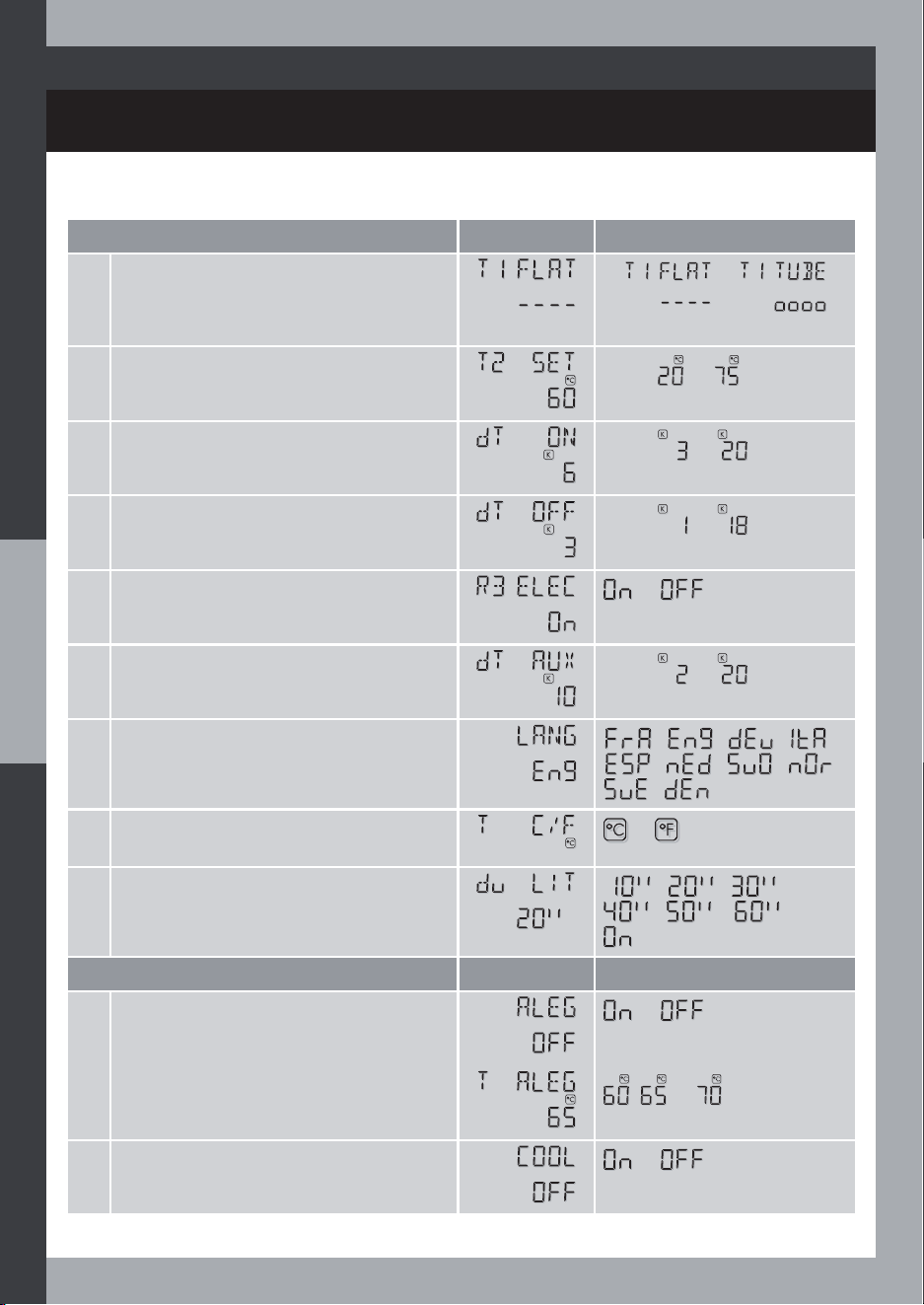
ALEG temperature set point 60°C 65°C 70°C
ALEG timeout
70 min. 5 min. 3 min.
Anti-legionella function summary
TU = Temperature in the Upper section of the Cylinder, T2SET = Cylinder Temperature setpoint, dTAUX =
Temperature difference (from the temperature setpoint) for Auxiliary heating authorization, OFPI = OFPP
Internal, OFPE = OFPP External
USER
MODE
HEAT
SOURCE
PERIOD /
TIME
HEAT / TEMPERATURE
START CONDITION
STOP
CONDITION
COMMENTS
ANTI-
LEGIONELLA
MAX HYD/ELEC
OFPP start
time + 1h
If AL heating
required
Timeout (once
hot)
1h at night if no
OFPP
ECO ELEC
23
COMFORT FUNCTIONS
AUXILIARY BACKUP HEATING
SOLAR PUMP CONTROL
7KH5VRODUSXPSFRQWURORXWSXWFDQEHFRQÀJXUHGWRIXQFWLRQLQRQHRIWKHWZRIROORZLQJ
control modes:
Basic On/Off control mode (ON/OFF):
the pump runs (at full speed) or not, no speed
FRQWUROIURP65FRQVWDQWYROXPHÁRZZKHQ21
Speed control mode (RPM):
this is a full-wave packet control mode for pump speed
YDULDWLRQXVLQJPHDVXUHGWHPSHUDWXUHV,I530PRGHLVVHWLQWKH©6HW&RQÀJªPRGHWKHQ
some other control settings (like the minimum speed ratio, eg 30%) may be re-set (in the «
Expert plus » mode).
Note: The installer will verify that the solar pump used in RPM mode is suitable in relation to
the R1 output and will check the minimum speed ratio of the controller with respect to the
pump type.
Using a basic / standard pump with no integrated electronic speed control
Either ON/OFF or RPM control mode can be used.
Using a pump with integrated electronic speed control
RPM control mode CANNOT be used, only ON/OFF control mode can be.
Auxiliary backup heating is only allowed under the condition that the temperature measured
DW7LQWKHVDQLWDU\KRWZDWHUVWRUDJHWDQNLVEHORZWKHFRQÀJXUHG´7VHWµYDOXH7LVWKHYDOXH
measured at the lower/bottom part of the hot water storage tank.
Feature electric auxiliary backup heating only :
Auxiliary
backup
type
Triggering conditions for auxiliary backup heating
Mode
SYSTEM 1
Basic solar
system with
ELectric
auxiliary
heating
R3(ELEC)
MAX+OFPP
R1=OFF
T3<T2Set
ECO+BOOST
-
MAX+BOOST
SYSTEM 2
Basic solar
system with
Solar pump
speed control
and ELectric
auxiliary
heating
R3(ELEC)
MAX+OFPP
R1=OFF
T3<T2Set
ECO+BOOST
-
MAX+BOOST
R1
R1
24

COMFORT FUNCTIONS
AUXILIARY BACKUP HEATING
SYSTEM 8
Solar system
with 2
cylinders,
3-way Valve
and Electric
auxiliary
heating
R3(ELEC)
MAX+OFPP
R1=OFF
T3<T2Set
+
(T4-T2)<dT
ECO+BOOST
-
MAX+BOOST
SYSTEM 9
Solar system
with 2
cylinders,
2nd Pump
and Electric
auxiliary
heating
R3(ELEC)
MAX+OFPP
R1=OFF
T3<T2Set
ECO+BOOST
-
MAX+BOOST
SYSTEM 12
Solar system
with East/
West collector
ÀHOGV))
and Electric
auxiliary
heating
R3(ELEC)
MAX+OFPP
R1=OFF
T3<T2Set
ECO+BOOST
-
MAX+BOOST
SYSTEM 13
Solar system
with 2-Layer
cylinder,
3-way Valve
and Electric
auxiliary
heating
R3(ELEC)
MAX+OFPP
R1=OFF
T3<T2Set
ECO+BOOST
-
MAX+BOOST
Auxiliary
backup
type
Triggering conditions for auxiliary backup heating
Mode
SYST8
2TKV
SYST12
E/W
SYST13
2LV
SYST9
2TKP
R3
R3
R3
R3
R1
R2
R1
R1
R1
OFPP = Off peak period
dT = Temperature difference
25
COMFORT FUNCTIONS
AUXILIARY BACKUP HEATING
Auxiliary backup type
Triggering conditions for auxiliary backup heating
Mode
SYSTEM 7
Pool solar
heating with
External Heat
Exchanger
R2
External heat
exchanger
MAX
(T3-T2)<dTA
ECO
SYSTEM 11
Solar system
with Heating
Return Increase
R2
Central
Heating Return
Increase
MAX
(T3-T4)<dTA
ECO
SYST11
HRI
R2
R2
R1
R1
Systems 7 & 11 do not feature electric auxiliary backup heating.
dTA = Temperature difference
Systems 3, 4 and 10 allow the connection of electric and hydraulic auxiliary back up heating
(e.g. by the means of a solid fuel boiler etc…).
Auxiliary
backup
type
Triggering conditions for auxiliary backup heating
Mode
SYSTEM 3
Solar system
with HYDraulic
and Electric
auxiliary
heating
R2 (HYD)
MAX
R1=OFF
T3<T2Set
MAX+BOOST -
R3 (ELEC)
ECO+BOOST -
R2
R1
R3
26
COMFORT FUNCTIONS
AUXILIARY BACKUP HEATING
OFPP = Off peak period
SYSTEM 4
Solar system
with Solar
pump speed
control,
HYDraulic
and Electric
auxiliary
heating
R2 (HYD)
MAX R1=OFF
T3<T2Set
MAX+BOOST
-
R3 (ELEC)
ECO+BOOST -
SYSTEM 10
Solar system
with Smart
Hydraulic
auxiliary
heating from
Solid fuel boiler
and Electric
auxiliary
heating
R2 (HYD)
MAX R1=OFF
T4>T4Min
+
T3<T2Set
MAX+BOOST
-
T3<T2Set
R3 (ELEC)
ECO+BOOST -
R2=OFF
+
T3<T2Set
+
T4<T4Min
MAX+OFPP R1=OFF
SYST4
HYPC
SYST10
HYSF
R3
R3
R1
R1
Auxiliary
backup
type
Triggering conditions for auxiliary backup heating
Mode
27
COMFORT FUNCTIONS
AUXILIARY BACKUP HEATING
System 5 : Electric and Hydraulic auxiliary backup heating are independent and can
operate simultaneously.
Auxiliary
backup
type
Triggering conditions for auxiliary backup heating
Mode
SYSTEM 5
Solar system
with External
Heat
EXchanger
and Electric
auxiliary
heating
R2 (HYD)
MAX
T3<T2Set
(T4-T2)>dT
ECO
R3 (ELEC)
MAX+OFPP
-
ECO+BOOST
MAX+BOOST
OFPP = Off peak period
dT = Temperature difference
R3
R2R1
28

COMFORT FUNCTIONS
STORAGE PRIORITY
COLD START FEATURE
The cold start feature is useful in cold climate conditions when there are long runs of pipe
work.
When this function is enabled, the switch-on temperature differential (dT ON) between the
collector and the cylinder is increased to 10°C if ever the collector temperature is lower than a
set limit (T1 COLD) and the solar pump has not run for 3 hours.
7KHLQVWDOOHUFDQGHÀQHDPLQLPXPUXQGXUDWLRQIRUWKHVRODUSXPSRUPLQ
:KHQDF\OLQGHUV\VWHPLVVHOHFWHGDSULRULW\F\OLQGHUFDQEHGHÀQHG
If one cylinder is higher priority
7KH35,2VHWWLQJLQWKH©6HW&RQÀJªPRGHGHÀQHVZKLFKF\OLQGHULVKLJKHVWSULRULW\WKHVWRUDJH
priority sets the priority according to which the storage cylinders are loaded.
,IWKHÀUVWSULRULW\F\OLQGHUWHPSHUDWXUHGLIIHUHQFHLVKLJKHUWKDQWKHVZLWFKRQOLPLWG721WKH
ÀUVWSULRULW\VWRUDJHF\OLQGHULVORDGHGXQWLOLWVWHPSHUDWXUHVHWSRLQWLVUHDFKHG2QO\WKHQVKRXOG
the second-priority cylinder be loaded.
If the second-priority cylinder temperature difference is higher than the switch-on limit (dT ON)
WKRXJK WKH ÀUVWSULRULW\ F\OLQGHU WHPSHUDWXUH GLIIHUHQFH LV QRW \HW WKHQ WKH VHFRQGSULRULW\
F\OLQGHULVORDGHGRQO\XQWLOWKHÀUVWSULRULW\F\OLQGHUKDVUHDFKHGWKHVZLWFKRQOLPLWG7217KLV
VZLWFKRQFRQGLWLRQLVSHULRGLFDOO\FKHFNHGGX35,2SHULRGVHWWLQJLQWKH©6HW&RQÀJªPRGH
while the second-priority cylinder is loaded.
If there is no loading priority
7KHFROGHUF\OLQGHULVORDGHGÀUVW7KLVWHPSHUDWXUHFRQGLWLRQLVSHULRGLFDOO\FKHFNHGGX35,2
SHULRGVHWWLQJLQWKH©6HW&RQÀJªPRGH
HEAT QUANTITY ESTIMATION
This function (only available for systems 1/3) requires an extra sensor (T4) to measure the return
ÁRZ WHPSHUDWXUH LW HVWLPDWHV WKH KHDW IHG LQWR WKH VWRUDJH F\OLQGHU IURP WKH VRODU HQHUJ\
supply system.
$EDVLFÁRZPHWHULVUHTXLUHG7KHYROXPH ÁRZYDOXHLQOLWUHVPLQXWHUHDGDWWKH ÁRZPHWHU
have to be entered at the SR controller settings (FL L/M).
,IDJO\FRODQWLIUHH]HOLTXLGLVXVHGWKHKHDWWUDQVIHUÁXLGVKDOOEHGHÀQHGWKHJO\FROW\SHDQG
concentration have to be set at the controller.
Heat Quantity Estimation (HQ) to be read in the INFO mode:
HQ KWh Heat Quantity during the last 24H
HQ MWh Heat Quantity in total
29
SYSTEM STATE AND DISPLAY
SYSTEM INFORMATION DISPLAY
System information display
From Auto mode, by pressing or successively several times, the system
information are scrolled through on screen.
System information
Display Related systems
1 T1 temperature
2 T2 temperature
3 dT temperature
4 T3 temperature
5 T4 temperature
6 dTA temperature = T1-T4
(if heat quantity function enabled)
7 dTA temperature = T4-T2
8 dTA temperature = T3-T2
9 dTA temperature = T1-T4
10 dTA temperature = T4-T3
11 dTA temperature = T3-T4
12 dTA temperature = T1-T3
13 R1 output
14 R2 output
(if Anti-Legionella function
enabled)
15 R2 output
16 R3 output
17 E1 input
18 Clock time
30
SYSTEM INFORMATION DISPLAY
SYSTEM STATE AND DISPLAY
Note
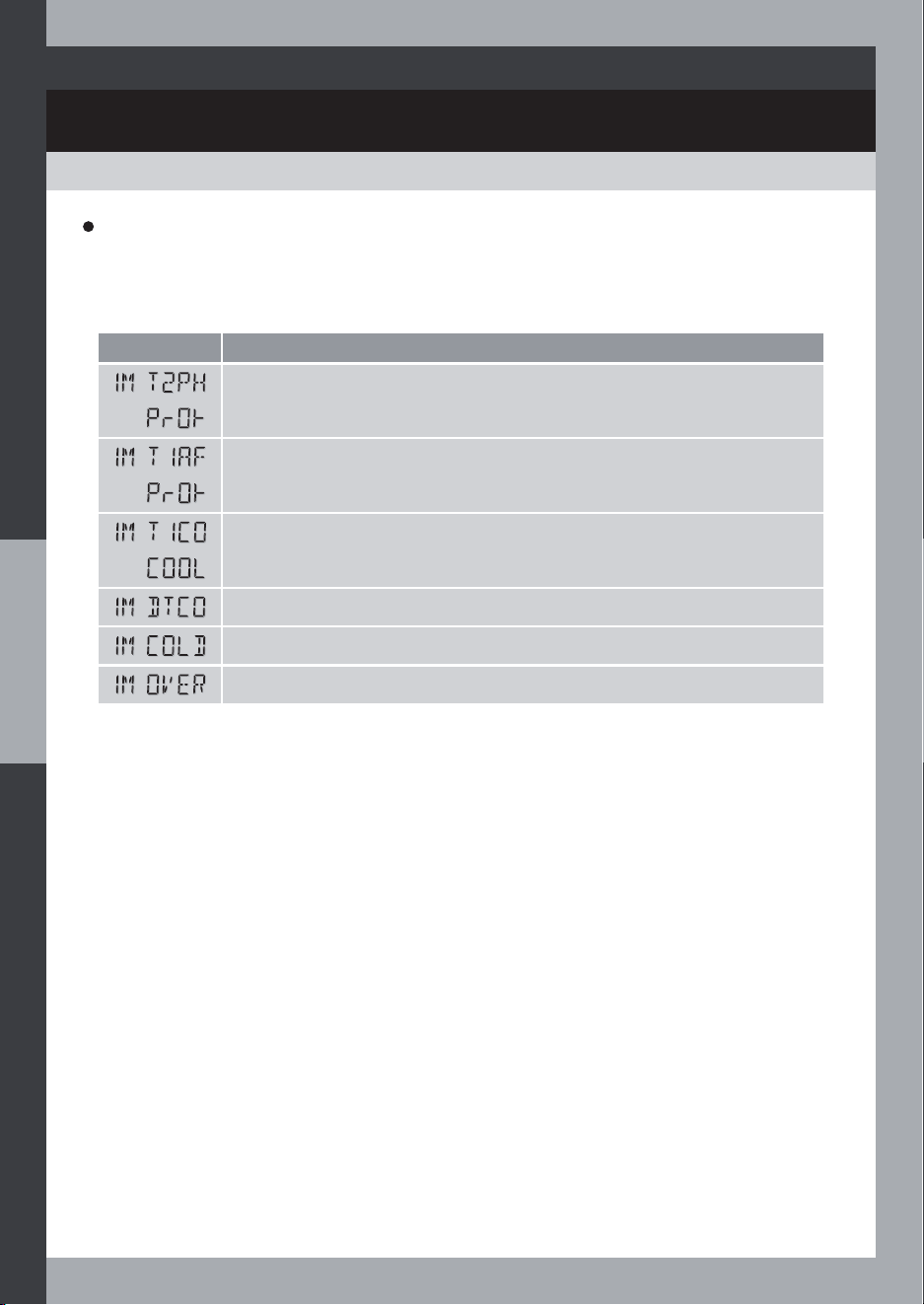
$Q,QIRUPDWLRQ0HVVDJH,0LVDUXQWLPHPHVVDJHZKLFKVLJQDOVWKDWDVSHFLÀFRSHUDWLRQOLNH
eg the system protection is currently running, it is displayed with the system information.
Display Function
System Protection against High temperature running at T2
AF protection running (at collector)
Cooling running at T1
DTCO delay running
Cold start function running
Pump overrun function running
31
STATISTICS
SYSTEM STATE AND DISPLAY
Statistics
Display Related systems
1 Heat Quantity/24H (if fonction
enabled)
2 Heat Quantity/total (if fonction
enabled)
3 R1 output on time count for the
last 24 hours
4 R1 output on time count in total
5 R2 output on time count for the
last 24 hours
6 R2 output on time count in total
7 R3 output on time count for the
last 24 hours
8 R3 output on time count in total
9 T1 minimum/day
10 T1 maximum/day
11 T2 minimum/day
12 T2 maximum/day
13 T3 minimum/day
14 T3 maximum/day
15 T4 minimum/day
16 T4 maximum/day
32
Statistics display
From Auto mode, press to access Statistics display.
You can scroll through the statistics, using or .

SAFETY ADVICE
PROPER USAGE
EXCLUSION OF LIABILITY
The temperature differential controller may only be used for controlling solar thermal systems
within the permissible ambient conditions.
Statistical information displayed by the controller is only indicative.
The controller must not be operated in outdoor or damp room environments.
> Check the display regularly.
> As soon as you detect a fault that you cannot resolve (see section Troubleshooting), switch
off the power supply.
DETECTING FAULTS
DANGERS DURING INSTALLATION AND OPERATIONS
DANGER
Risk of electrocution!
The following risks appear during installation, initial use of the controller or operations (in case
of installation errors):
! 5LVNRIÀUHGXHWRVKRUWFLUFXLWLQJ
> Damage to the controller or to the connected devices due to improper ambient
conditions, inappropriate power supply or connection of inadequate any or faulty
GHYLFHVRUGHYLFHVQRWFRYHUHGLQWKHVSHFLÀFDWLRQVDVZHOODVLQFRUUHFWDVVHPEO\
or installation.
Note: 2EVHUYHWKHFRQWUROOHU·VUDWLQJVDQGVSHFLÀFDWLRQV
Therefore, set-up and connection to the mains must comply with safety standards or regional
regulations. Only electricians may perform work that requires the controller being opened
(such as electrical connection work).
HOT WATER TEMPERATURE
In order to limit the hot water temperature to 60 °C at the outlets, a hot water mixer must be
installed.
7KHV\VWHPGLDJUDPRQVFUHHQLVPHUHO\DVLPSOLÀHGGLVSOD\UHSUHVHQWLQJWKHDFWXDOV\VWHPLWLV
WKHVROHUHVSRQVLELOLW\RIWKHLQVWDOOHUWRGHÀQHDQGVHWXSWKHSURSHUK\GUDXOLFV\VWHPLQFOXGLQJ
adequate safety devices (the expansion vessel, valves, a safety thermostat if required, etc...).
The manufacturer can neither monitor compliance with this manual nor particulars regarding
and methods employed during the course of set-up operation, use and maintenance of the
controller. Improper set-up of the system may result in damage to property and, as a result, in
bodily injury.
Therefore, the manufacturer assumes no responsibility or liability for loss, damage or costs which
arise out of or which in any way related to incorrect set-up, improper operation, incorrect
performance of installation work and incorrect usage or maintenance.
The manufacturer reserves the right to make changes to the product, to technical data and to
installation and operating instructions without prior notice.
33
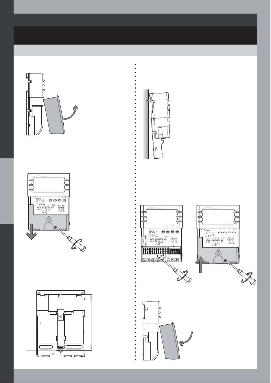
WALL INSTALLATION
MOUNTING
34
130 mm
Fixing
Fixing
0DUN WKH XSSHU À[LQJ SRLQW RQ WKH ZDOO
and set the wall plug and screw leaving
the head protruding.
2- Unscrew the screw at the bottom of
the product, and remove the terminal
cover.
μ 1A
250V~
1- Remove the front cover. +DQJ WKH KRXVLQJ RQ WKH XSSHU À[LQJ
SRLQW DQG PDUN WKH ORZHU À[LQJ SRLQW
through the hole in the housing socket.
Set the lower wall plug.
Distance between
the attachment
points: 130 mm.
μ 1A
250V~
5- Fasten the
housing on
to the wall by
À[LQJWKHORZHU
screw.
6- Fit the terminal
cover on to the
cabinet and
tighten the screw
at the bottom of
the product.
μ 1A
250V~
7- Fit the front cover on to the device.
MOUNTING
PUMP STATION INSTALLATION
INSTALLATION ON A DIN RAIL
<RX FDQ XVH WKH WZR À[LQJ KROHSDLU DW WKH
XSSHUEDFNVLGHRIWKHFRQWUROOHUWRÀ[LWZKHQ
it is inserted in a pump station.
Use self-tapping screws.
35
1- Mounting
Hang the controller on the upper edge of
the DIN rail.
Then push the controller at the bottom, the
solar controller will lock automatically on
the rail.
2- Unmounting
First take off the terminal cover.
Draw the hook towards the bottom with a
VFUHZGULYHUWRXQORFNWKHUDLOÀ[LQJ
Meanwhile take off the solar controller.
CLICK
~
POWER SUPPLY AND ELECTRICAL
CONNECTIONS
OVERVIEW
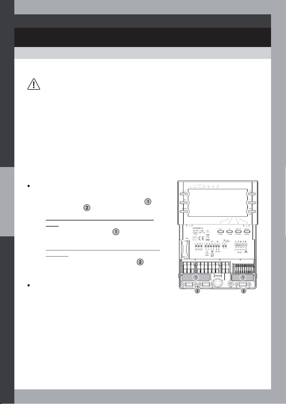
NOTE
The solar system and actuators (pumps, valve, etc…) may be connected to earth thru the
Earth terminals of the SR controller.
The installation shall comply with applicable safety regulations (including EN60730 standard)
and local installation guidelines, especially the SR device is to be connected via a
disconnection device i.e. a circuit breaker or a detachable external fuse.
Preparing the cable feed
Depending on the type of installation, the cables may
enter the device through the rear of the case or the
lower side of the case .
- Feeding the cable through the rear of the
case
5HPRYHWKHSODVWLFÁDSV
from the rear side
of the case using an appropriate tool.
- Feeding the cable through the lower side of
the case
&XWWKHOHIWDQGULJKWSODVWLFÁDSV
using an
appropriate tool.
Connecting the cables
> The terminals are approved for connection of
cables as follows:
- Max wire section for power terminals = 2,5 mm²
- Max wire section for signal terminals = 0,5 mm²
> Only use the original temperature sensors (Pt1000) that are approved for use with the
controller. Observe the following points:
- The polarity of the temperature sensor contacts is not important.
- Do not lay sensor cables close to power cables.
- Sensor cables may be extended (use 0,75 mm² min wires).
> Observe the terminal pinout diagram and system wiring diagrams.
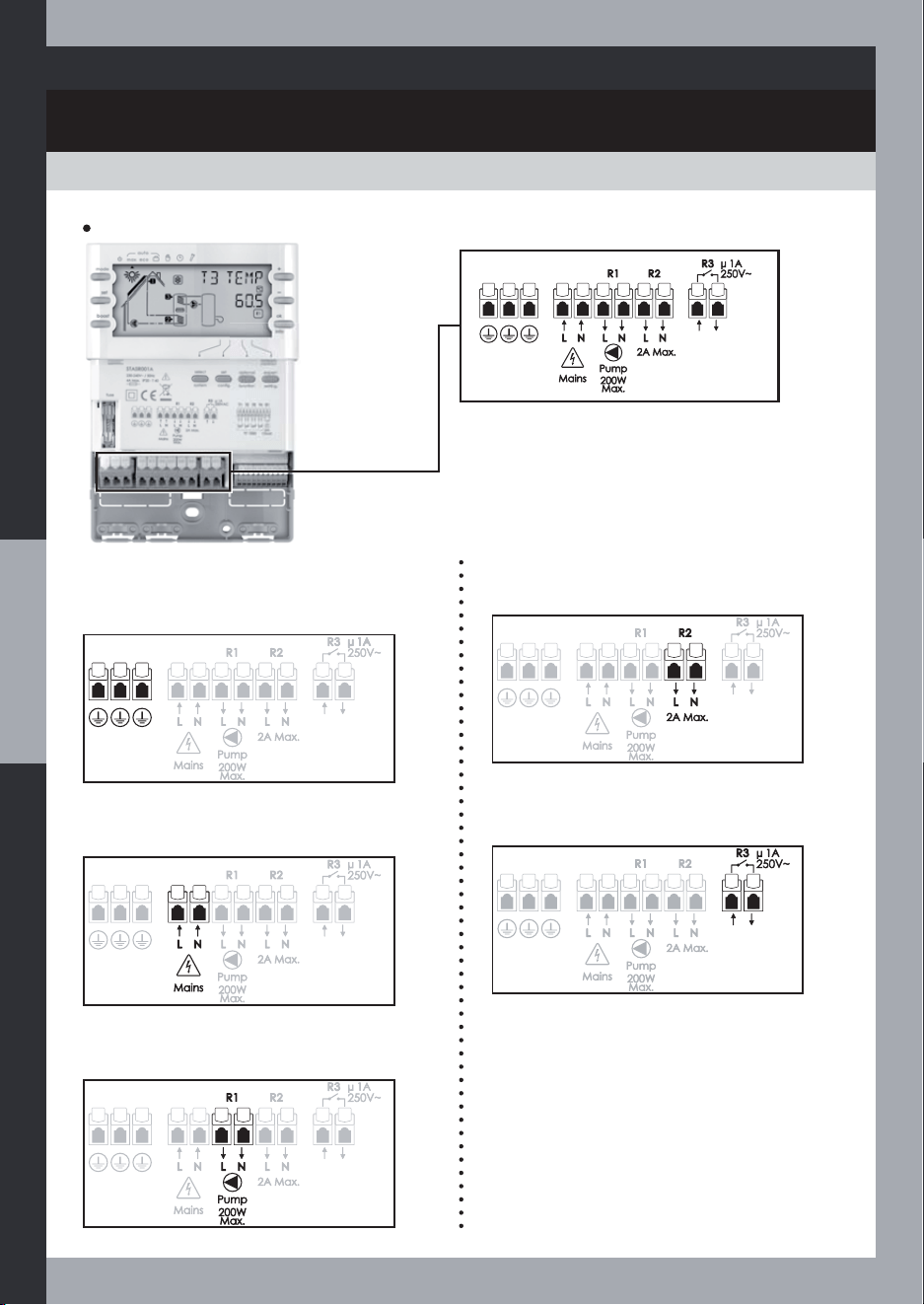
L NL N L N
R3
T1 T2 T3 T4 E1R1 R2
μ 1A
250V~
Mains
Pump
200W
Max.
2A Max.
PT 1000
Ext
Clock
STASR001A
230-240V~ / 50Hz
4A Max. IP20 - T 50
DANGER
Risk of death by electrocution!
1- Switch off the power supply of the controller before removing the terminal cover.
2- Remove the controller from the power supply before opening the case.
3- Only switch the power supply back on after the casing has been closed.
7KHHOHFWULFDOFRQQHFWLRQPXVWEHFDUULHGRXWE\DTXDOLÀHGSURIHVVLRQDOLQVWDOOHU
36
POWER SUPPLY AND ELECTRICAL
CONNECTIONS
OVERVIEW
Earth terminals
The earth brought with the power supply
can be connected to the actuators (eg.
the solar pump).
Power supply terminals
L = Line
N = Neutral
R1 output terminals
L = Switched output Line
N = Neutral
Power connections
37
R2 output terminals
L = Switched output Line
N = Neutral
R3 output terminals
Free-voltage output switch
POWER SUPPLY AND ELECTRICAL
CONNECTIONS
OVERVIEW
Signal connections
38
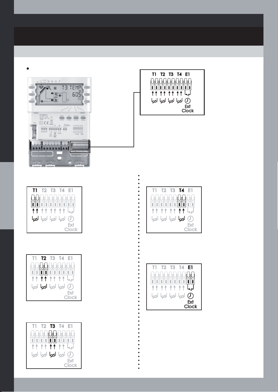
T1 sensor input
No polarity
T2 sensor input
No polarity
T3 sensor input
No polarity
T4 sensor input
No polarity
E1 synchronisation input
To be connected to an external time
switch
POWER SUPPLY AND ELECTRICAL
CONNECTIONS
FUSE REPLACE
CONNECTIONS
DANGER
Risk of death by electrocution!
1- Before opening the case, remove the controller from the power supply.
2- Unfasten the screw and take off the terminal cover.
3- Remove the blown fuse from the fuse holder.
4- Remove the spare fuse from behind the terminal cover and mount it in the fuse holder.
5- Then you may supply the controller again.
39
Spare fuse
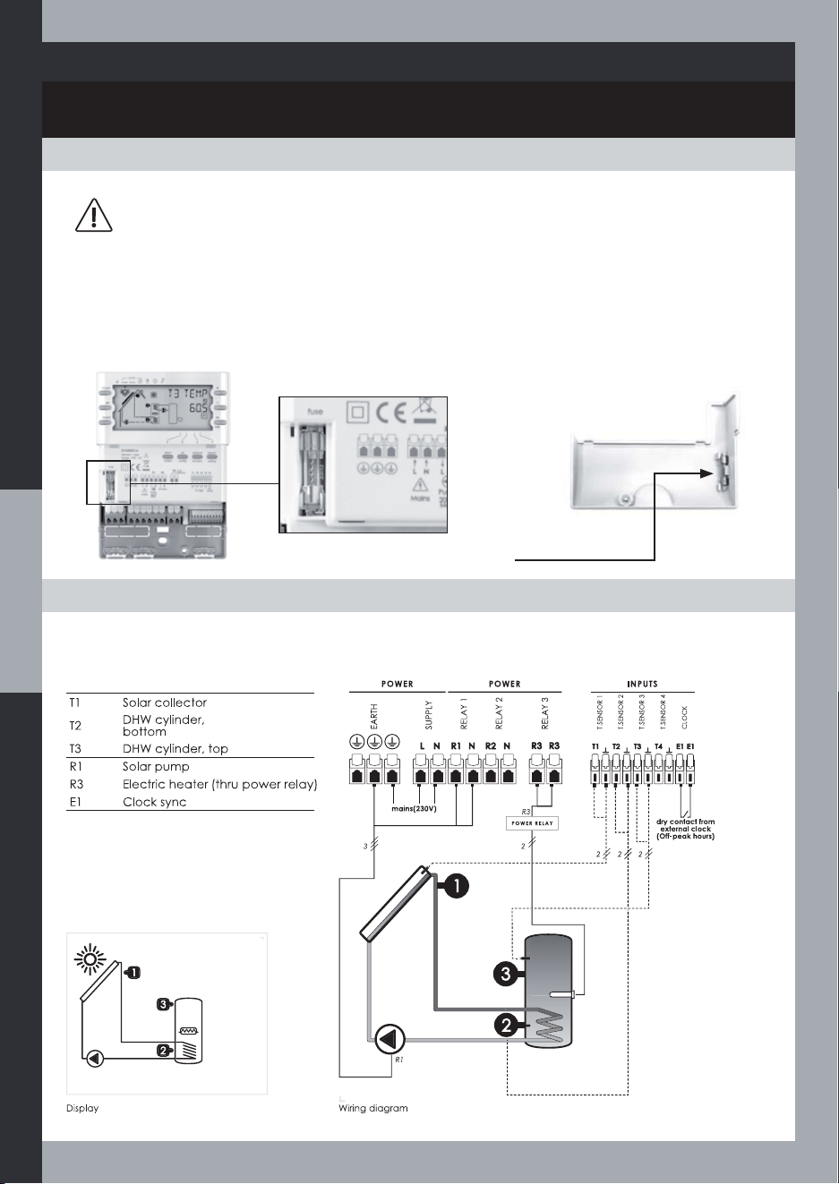
Syst 1
Basic solar system with ELectric auxiliary heating
POWER SUPPLY AND ELECTRICAL
CONNECTIONS
CONNECTIONS
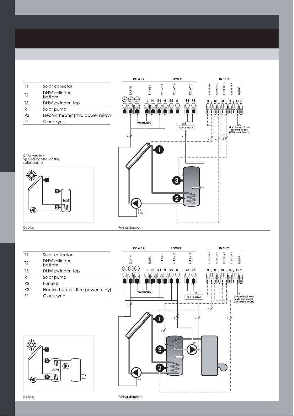
Syst 2
Basic solar system with Solar pump speed control and ELectric auxiliary heating
40
Syst 3
Solar system with HYDraulic and Electric auxiliary heating
POWER SUPPLY AND ELECTRICAL
CONNECTIONS
CONNECTIONS
41
Syst 4
Solar system with Solar pump speed control, HYDraulic and Electric auxiliary heating
Syst 5
Solar system with External Heat EXchanger and Electric auxiliary heating
POWER SUPPLY AND ELECTRICAL
CONNECTIONS
CONNECTIONS
42
Syst 6
Basic POOL solar system
Syst 7
Pool solar heating with External Heat Exchanger
POWER SUPPLY AND ELECTRICAL
CONNECTIONS
CONNECTIONS
43
Syst 8
Solar system with 2 cylinders, 3-way Valve and Electric auxiliary heating
Syst 9
Solar system with 2 cylinders, 2nd Pump and Electric auxiliary heating
POWER SUPPLY AND ELECTRICAL
CONNECTIONS
CONNECTIONS
44
Syst 10
Solar system with Smart Hydraulic auxiliary heating from Solid fuel boiler and Electric
auxiliary heating
Syst 11
Solar system with Heating Return Increase
POWER SUPPLY AND ELECTRICAL
CONNECTIONS
CONNECTIONS
45
Syst 12
6RODUV\VWHPZLWK(DVW:HVWFROOHFWRUÀHOGV))DQG(OHFWULFDX[LOLDU\KHDWLQJ
Syst 13
Solar system with 2-Layer cylinder, 3-way Valve and Electric auxiliary heating
INSTALLER SET
SETTING ACCESS
You can modify the default settings by entering one of the four Install modes :
6HW&RQÀJWRVHWWKHV\VWHPFRQÀJXUDWLRQLHWKHPDLQV\VWHPSDUDPHWHUV
- Optional Function: to set some optional functions
- Expert Setting: to set some expert parameters
- Expert Setting Plus: to set some secondary expert parameters
Restoring factory settings (reset)
The Reset function restores the factory
settings for all parameters.
To restore factory settings, press
and
and hold them down for 10 seconds.
10 sec.
Setting Lock
2QFH VHWWLQJ LV ÀQLVKHG \RX FDQ ORFN WKH
Install settings (so that the user is only able
to change the User settings).
From Expert Mode, press
and
and hold them down for 5 seconds.
Then press
and and hold
them down for 5 seconds to unlock the
keys.
5 sec.
How to set the product
1- Select system :
Press the button .
Select a system using
or .
Save by pressing
.
6HW&RQÀJ
Press the button .
6HOHFW WKH FRQÀJXUDWLRQ SDUDPHWHUV IRU WKH
selected system, using
or .
Press to modify.
Save by pressing
.
3- Optional function:
Press the button .
Select the options for the selected system,
using
or .
Press
to modify.
Save by pressing
.
4- Expert Setting:
Press the button .
Select the parameters for the selected system,
using
or .
Press
to modify.
Save by pressing
.
5- Expert Setting Plus:
Press the button
and hold it down for 5 seconds.
Select the parameters for the selected system,
using
or .
Press to modify.
Save by pressing
.
46
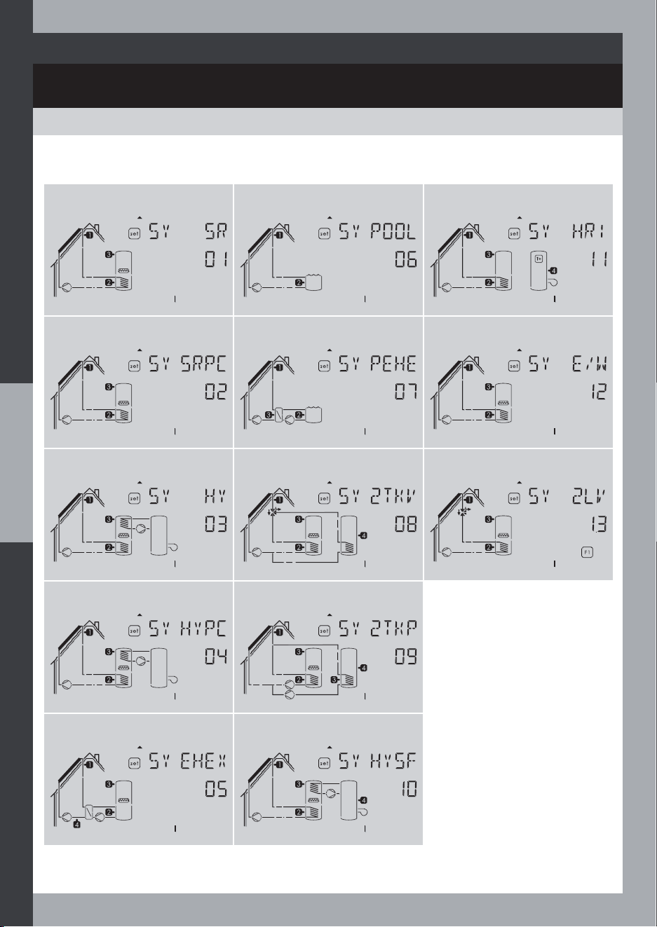
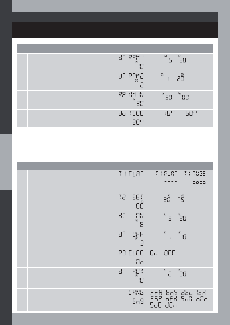
SELECT SYSTEM
INSTALLER SET
System 01 System 06 System 11
System 02 System 07 System 12
System 03 System 08 System 13
System 04 System 09
System 05 System 10
47
13 systems
INSTALLER SET
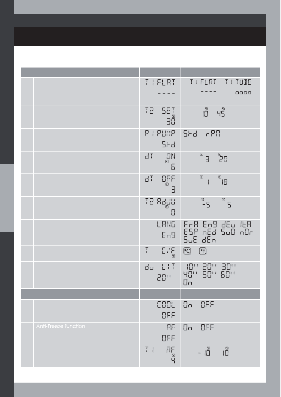
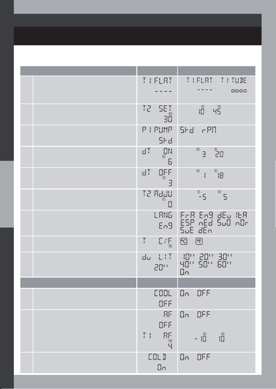
SYST. 01
6HW&RQÀJ
Factory Setting
Values
1 Collector Type
or
2 Cylinder temperature setpoint
From to
3 Temperature difference to switch on the
solar heating
From to
4 Temperature difference to switch off the
solar heating
From to
5 R3 output
or
6 Temperature difference (from the
temp. setpoint) for Auxiliary heating
authorization
From to
7 Language
- - -
- - -
-
8 Degree unit
or
9 Display / light timeout
- -
- -
Optional function
Factory Setting
Values
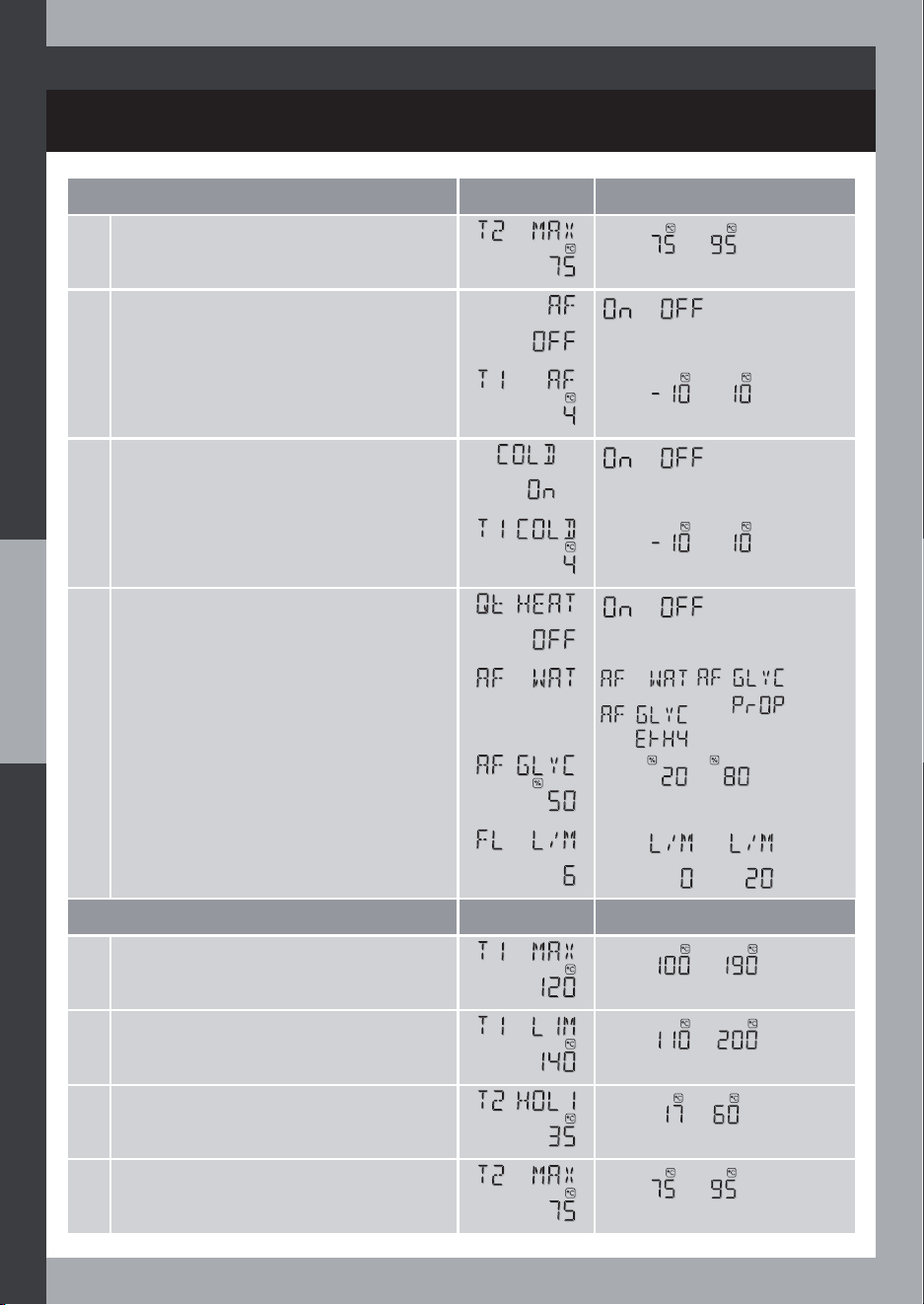
1 Anti-Legionella function
or
2 Anti-Legionella temperature threshold
, or
3 Cooling (safety function)
or
48
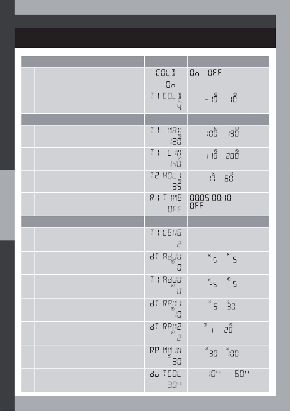
SYSTEM 01: Basic solar system with Electric auxiliary heating
INSTALLER SET
SYST. 01
Optional function
Factory Setting
Values
4 Maximum cylinder temperature (safety)
From to
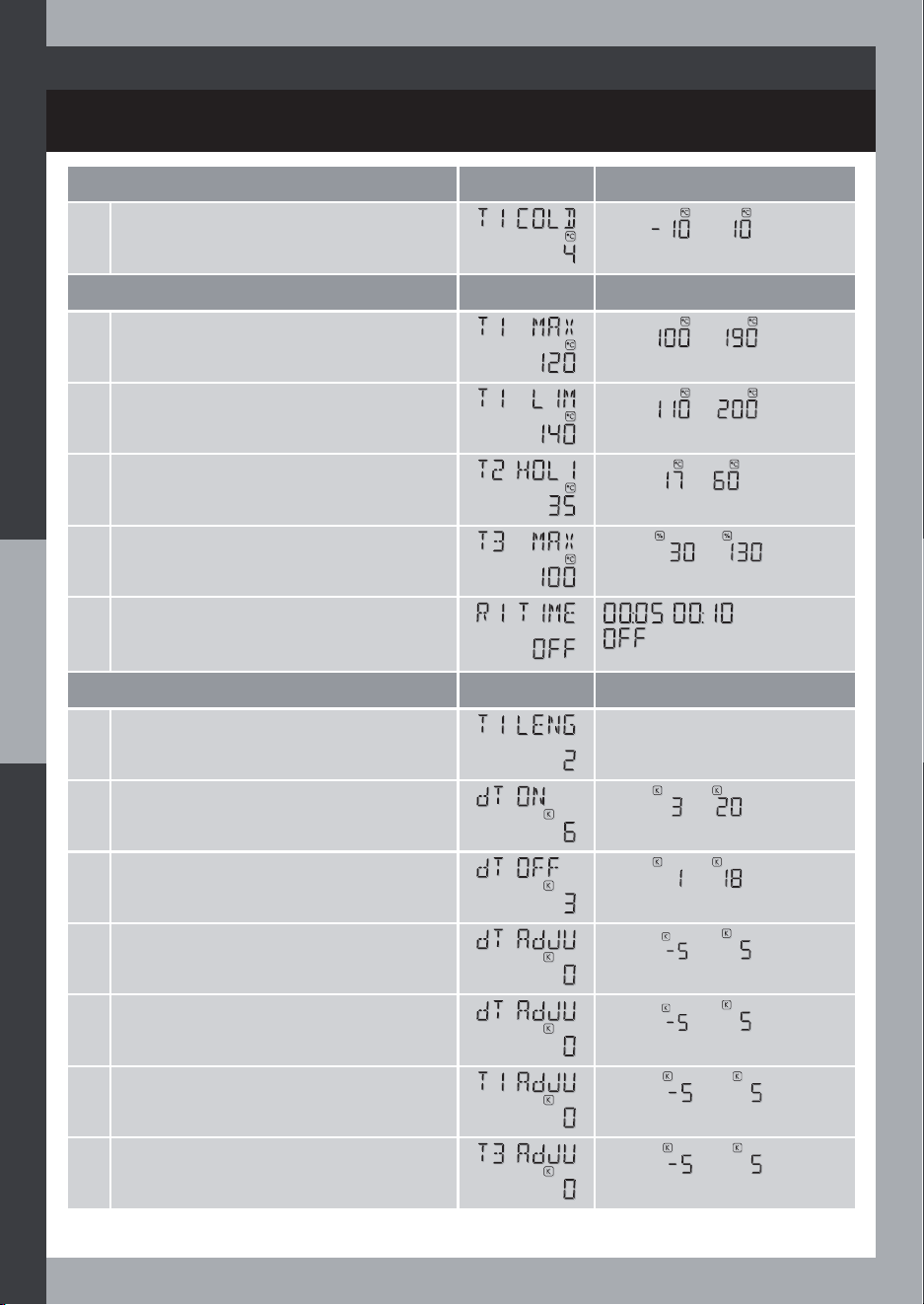
5 Anti-Freeze function
or
6 Anti-Freeze temperature threshold
From to
7 Cold start function
or
8 Cold start temperature threshold
From to
9 Heat Quantity
Estimation function
or
10 Anti-Freeze Áuid type
,
or
11 Anti-freeze glycol concentration rate
From to
12 Flow Rate from Meter Reading
From to
Expert Setting
Factory Setting Values
1 Maximum collector temperature
From to
2 Collector temperature safety limit
From to
3 Night temperature setpoint
(for HOLIDAYS mode)
From to
4 Maximum cylinder temperature (safety)
From to
49
INSTALLER SET
SYST. 01
Expert Setting
Factory Setting
Values
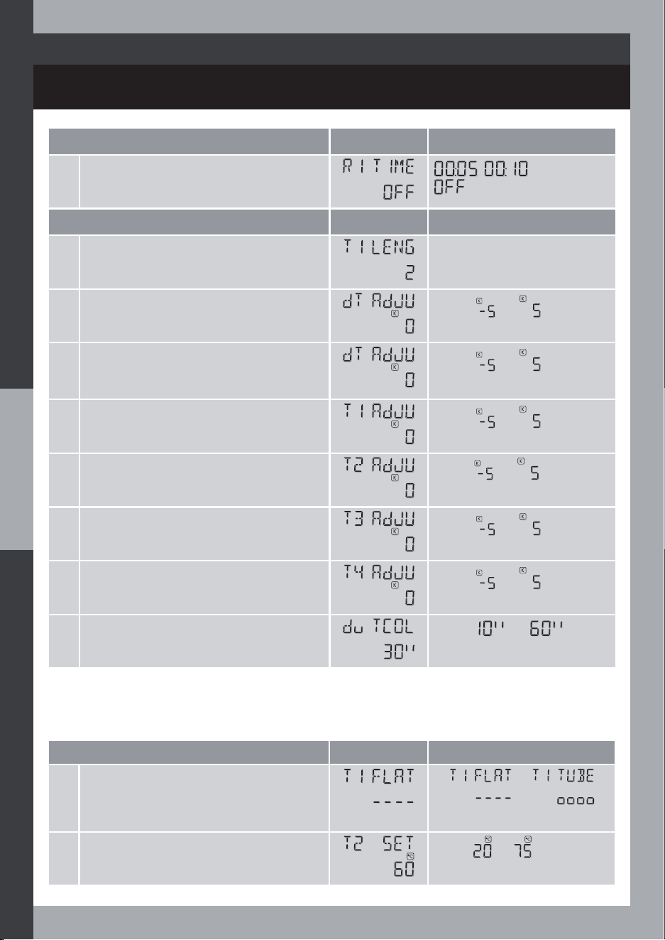
5 Minimum pump-on duration
, or
Expert Setting Plus
Factory Setting
Values
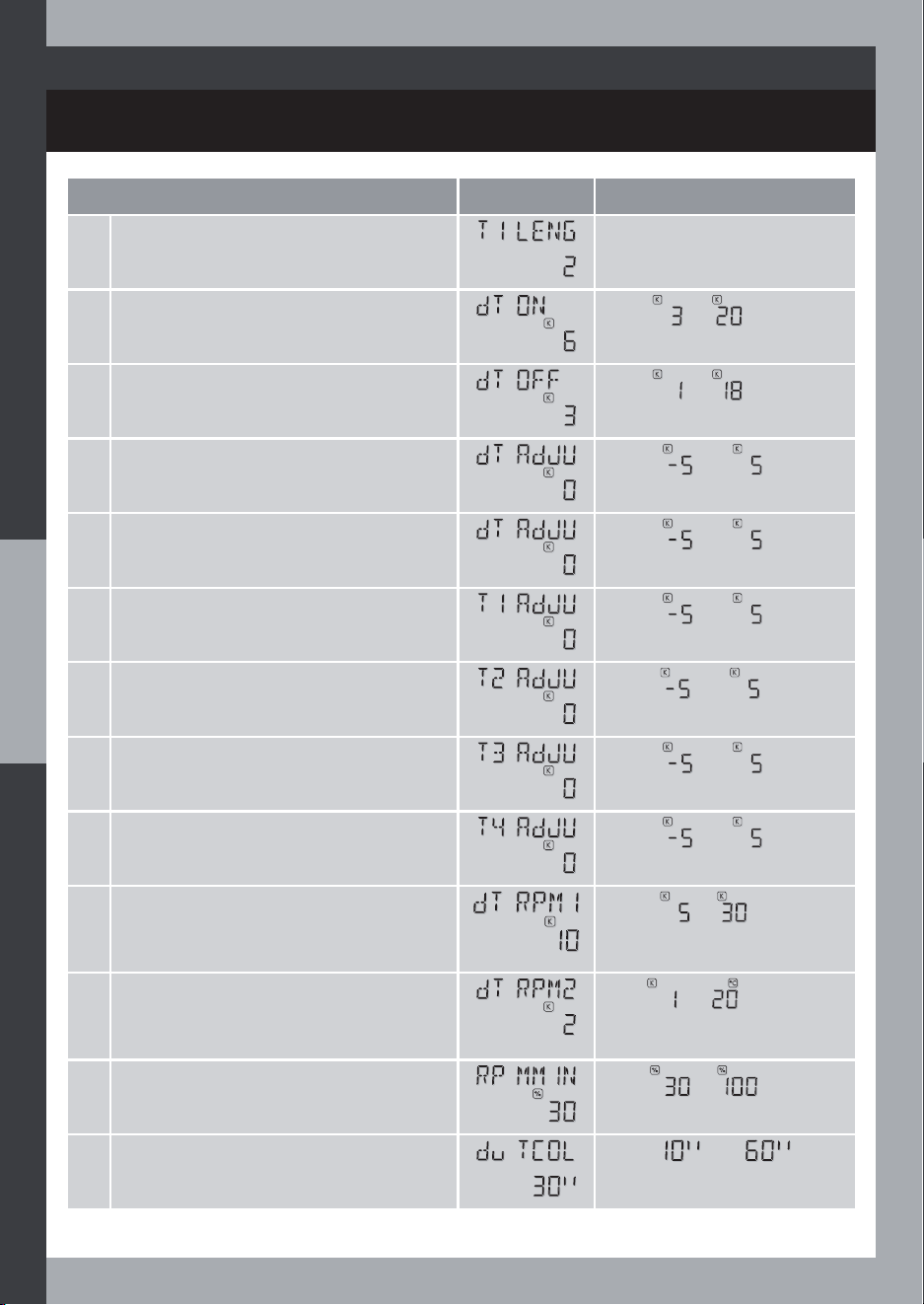
1 Collector probe length
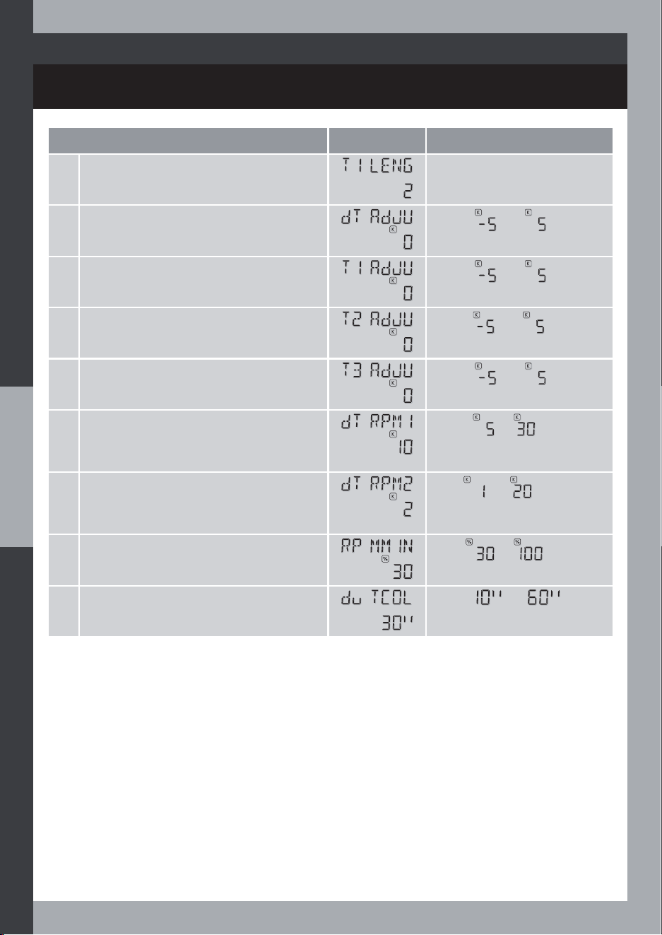
2 Temperature difference zero adjustment
value
From to
3
Additional temperature difference zero
adjustment value
(if Heat Quantity function enabled)
From to
4 T1 temperature zero adjustment value
From to
5 T2 temperature zero adjustment value
From to
6 T3 temperature zero adjustment value
From to
7 T4 temperature zero adjustment value
(if Heat Quantity function enabled)
From to
8 Tube collector temperature test duration
(if TUBE type collector)
From to
6HW&RQÀJ
Factory Setting Values
1 Collector Type
or
2 Cylinder temperature setpoint
From to
50
SYSTEM 02: Basic solar system with Solar pump speed control
(RPM) and Electric auxiliary heating
INSTALLER SET
6HW&RQÀJ
Factory Setting Values
3 Temperature difference to switch on the
solar heating
From to
4 Temperature difference to switch off the
solar heating
From to
5 R3 output
or
6 Temperature difference (from the
temp. setpoint) for Auxiliary heating
authorization
From to
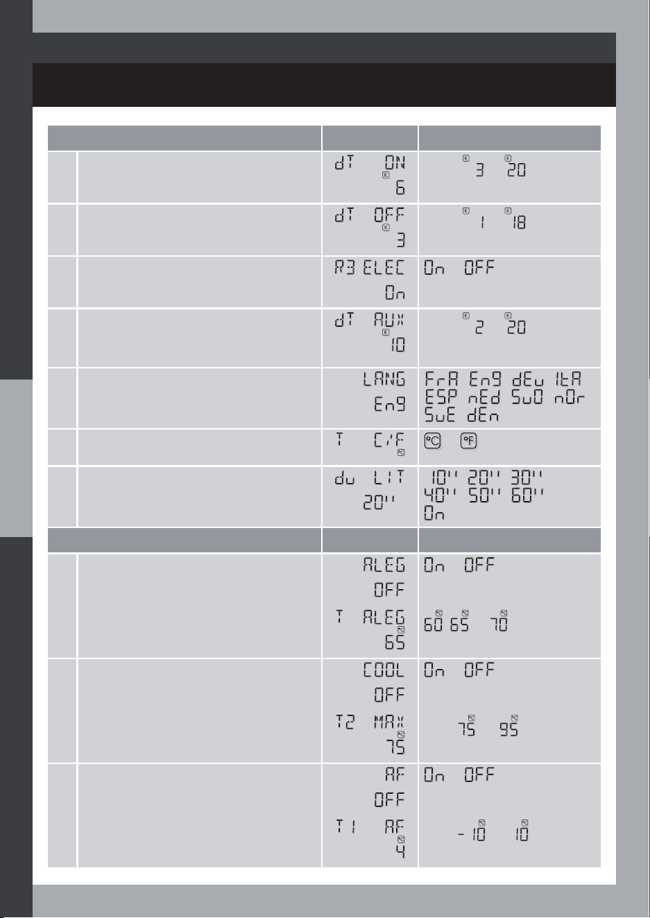
7 Language
- - -
- - -
-
8 Degree unit
or
9 Display / light timeout (except for
INSTALL)
- -
- -
Optional function
Factory Setting Values
1 Anti-Legionella function
or
2 Anti-Legionella temperature threshold
, or
3 Cooling (safety function)
or
4 Maximum cylinder temperature (safety)
From to
5 Anti-Freeze function
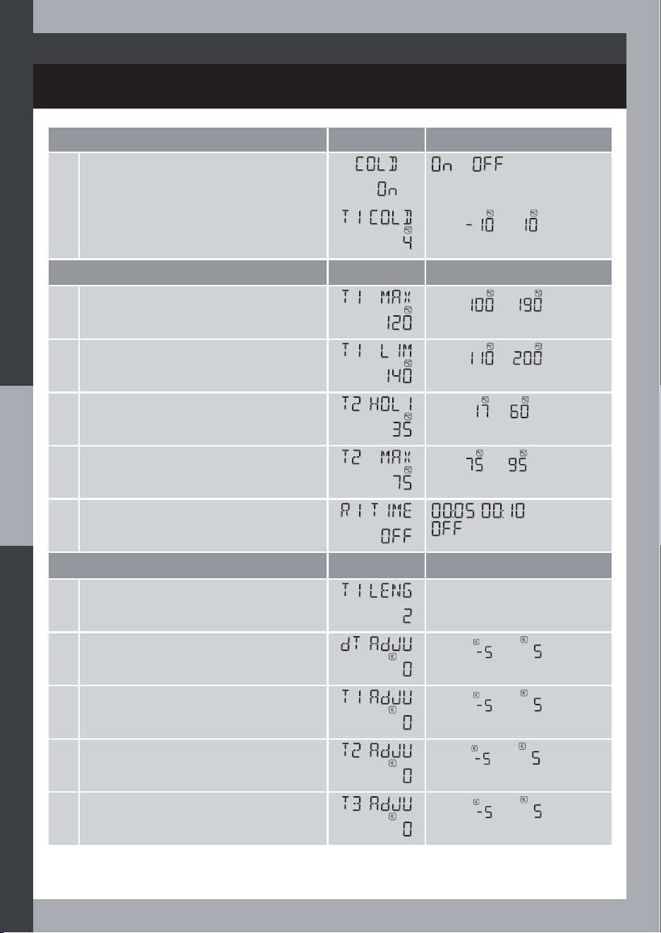
or
6 Anti-Freeze temperature threshold
From to
51
SYST. 02
INSTALLER SET
Optional function
Factory Setting Values
7 Cold start function
or
8 Cold start temperature threshold
From to
Expert Setting
Factory Setting Values
1 Maximum collector temperature
From to
2 Collector temperature safety limit
From to
3 Night temperature setpoint (for
HOLIDAYS mode)
From to
4 Maximum cylinder temperature (safety)
From to
5 Minimum pump-on duration
, or
Expert Setting Plus
Factory Setting Values
1 Collector probe length
2 Temperature difference zero adjustment
value
From to
3 T1 temperature zero adjustment value
From to
4 T2 temperature zero adjustment value
From to
5 T3 temperature zero adjustment value
From to
52
SYST. 02
INSTALLER SET
6HW&RQÀJ
Factory Setting Values
1 Collector Type
or
2 Cylinder temperature setpoint
From to
3 Temperature difference to switch on the
solar heating
From to
4 Temperature difference to switch off the
solar heating
From to
5 R3 output
or
6 Temperature difference (from the
temp. setpoint) for Auxiliary heating
authorization
From to
7 Language
- - -
- - -
-
Expert Setting Plus
Factory Setting Values
6 Nominal temperature difference for
pump speed control
From to
7 Unit temperature difference for pump
speed control
From to
8 Minimum pump speed ratio
From to
9 Collector temperature test duration (if
tube collector type)
From to
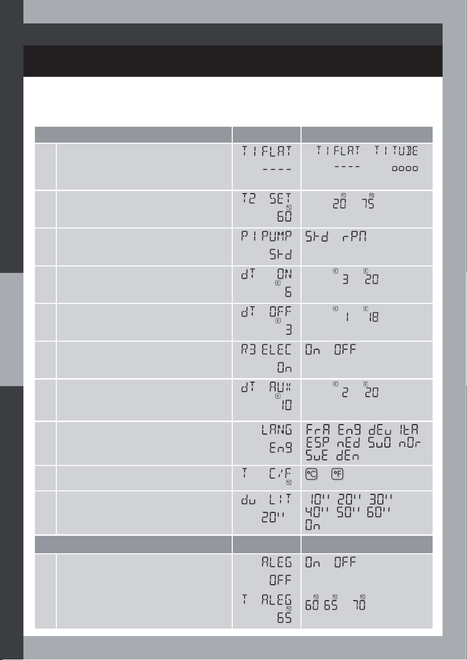
53
SYSTEM 03: Basic solar system with Hydraulic and
Electric auxiliary heating
SYST. 02
INSTALLER SET
6HW&RQÀJ
Factory Setting Values
8 Degree unit
or
9 Display / light timeout
- -
- -
Optional function
Factory Setting Values
1 Anti-Legionella function
or
2 Anti-Legionella temperature threshold
, or
3 Cooling (safety function)
or
4 Maximum cylinder temperature (safety)
From to
5 Anti-Freeze function
or
6 Anti-Freeze temperature threshold
From to
7 Cold start function
or
8 Cold start temperature threshold
From to
9 Heat Quantity
Estimation function
or
10 Anti-Freeze Áuid type
,
or
11 Anti-freeze glycol concentration rate
From to
54
SYST. 03
Optional function
Factory Setting Values
12 Flow Rate from Meter Reading
From to
Expert Setting
Factory Setting Values
1 Maximum collector temperature
From to
2 Collector temperature safety limit
From to
3 Night temperature setpoint
(for HOLIDAYS mode)
From to
4 Maximum cylinder temperature (safety)
From to
5 Minimum pump-on duration
, or
Expert Setting Plus
Factory Setting Values
1 Collector probe length
2 Temperature difference zero adjustment
value
From to
3 Additional temperature difference zero
adjustment value
(if Heat Quantity enabled)
From to
4 T1 temperature zero adjustment value
From to
5 T2 temperature zero adjustment value
From to
6 T3 temperature. zero adjustment value
From to
55
INSTALLER SET
SYST. 03
INSTALLER SET
SYST. 03
Expert Setting Plus
Factory Setting Values
7 T4 temperature zero adjustment value
(if Heat Quantity enabled)
From to
8 Tube collector temperature test duration
(if TUBE type collector)
From to
6HW&RQÀJ
Factory Setting Values
1 Collector Type
or
2 Cylinder temperature setpoint
From to
3 Temperature difference to switch on the
solar heating
From to
4 Temperature difference to switch off the
solar heating
From to
5 R3 output
or
6 Temperature difference (from the
temp. setpoint) for Auxiliary heating
authorization
From to
7 Language
- - -
- - -
-
8 Degree unit
or
9 Display / light timeout
- -
- -
56
SYSTEM 04: Solar system with Solar pump speed control,
Hydraulic Auxiliary and Electric auxiliary heating

INSTALLER SET
SYST. 04
Optional function
Factory Setting Values
1 Anti-Legionella function
or
2 Anti-Legionella temperature threshold
, or
3 Cooling (safety function)
or
4 Maximum cylinder temperature (safety)
From to
5 Anti-Freeze function
or
6 Anti-Freeze temperature threshold
From to
7 Cold start function
or
8 Cold start temperature threshold
From to
Expert Setting
Factory Setting Values
1 Maximum collector temperature
From to
2 Collector temperature safety limit
From to
3 Night temperature setpoint
(for HOLIDAYS mode)
From to
4 Maximum cylinder temperature (safety)
From to
5 Minimum pump-on duration
, or
57
INSTALLER SET
SYST. 04
Expert Setting Plus
Factory Setting Values
1 Collector probe length
2 Temperature difference zero adjustment
value
From to
3 T1 temperature zero adjustment value
From to
4 T2 temperature zero adjustment value
From to
5 T4 temperature zero adjustment value
From to
6 Nominal temperature difference for
pump speed control
From to
7 Unit temperature difference for pump
speed control
From to
8 Minimum pump speed ratio
From to
9 Tube collector temperature test duration
(if TUBE type collector)
From to
58
INSTALLER SET
SYST. 05
6HW&RQÀJ
Factory Setting Values
1 Collector Type
or
2 Cylinder temperature setpoint
From to
3 R1 output, R1 pump control, ON/OFF
mode (STD) bor speed variation mode
(RPM)
or
4 Temperature difference to switch on the
solar heating
From to
5 Temperature difference to switch off the
solar heating
From to
6 R3 output
or
7 Temperature difference (from the
temp. setpoint) for Auxiliary heating
authorization
From to
8 Language
- - -
- - -
-
9 Degree unit
or
10 Display / light timeout
- -
- -
Optional function
Factory Setting Values
1 Anti-Legionella function
or
2 Anti-Legionella temperature threshold
, or
SYSTEM 05: Solar system with External Heat Exchanger
and Electric auxiliary heating
59
INSTALLER SET
SYST. 05
Optional function
Factory Setting Values
3 Cooling (safety function)
or
4 Maximum cylinder temperature (safety)
From to
5 Anti-Freeze function
or
6 Anti-Freeze temperature threshold
From to
7 Cold start function
or
8 Cold start temperature threshold
From to
Expert Setting
Factory Setting Values
1 Maximum collector temperature
From to
2 Collector temperature safety limit
From to
3 Night temperature setpoint
(for HOLIDAYS mode)
From to
4 Maximum cylinder temperature (safety)
From to
5 Maximum exchanger output
temperature
From to
6 Minimum pump-on duration
, or
60
INSTALLER SET
SYST. 05
Expert Setting Plus
Factory Setting Values
1 Collector probe length
2 Temperature difference to switch on the
solar heating from the exchanger
From to
3 Temp. difference to switch off the solar
heating from the exchanger
From to
4 Temperature difference zero adjustment
value
From to
5 Additional temperature difference zero
adjustment value
From to
6 T1 temperature zero adjustment value
From to
7 T2 temperature zero adjustment value
From to
8 T3 temperature zero adjustment value
From to
9 T4 temperature zero adjustment value
From to
10 Nominal temperature difference for
pump speed control
From to
11 Unit temperature difference for pump
speed control
From to
12 Minimum pump speed ratio
From to
13 Tube collector temperature test duration
(if TUBE type collector)
From to
61
INSTALLER SET
SYST. 06
6HW&RQÀJ
Factory Setting Values
1 Collector Type
or
2 Cylinder temperature setpoint
From to
3 R1 output, R1 pump control, ON/OFF
mode (STD) bor speed variation mode
(RPM)
or
4 Temperature difference to switch on the
solar heating
From to
5 Temperature difference to switch off the
solar heating
From to
6 T2 temperature zero adjustment value
From to
7 Language
- - -
- - -
-
8 Degree unit
or
9 Display / light timeout
- -
- -
Optional function
Factory Setting Values
1 Cooling (safety function)
or
2 Anti-Freeze function
or
3 Anti-Freeze temperature threshold
From to
62
SYSTEM 06: Basic pool solar heating
INSTALLER SET
SYST. 06
Optional function
Factory Setting Values
4 Cold start function
or
5 Cold start temperature threshold
From to
Expert Setting
Factory Setting Values
1 Maximum collector temperature
From to
2 Collector temperature safety limit
From to
3 Night temperature setpoint
(for HOLIDAYS mode)
From to
4 Minimum pump-on duration
, or
Expert Setting Plus
Factory Setting Values
1 Collector probe length
2 Temperature difference zero adjustment
value
From to
3 T1 temperature zero adjustment value
From to
4 Nominal temperature difference for
pump speed control
From to
5 Unit temperature difference for pump
speed control
From to
6 Minimum pump speed ratio
From to
7 Tube collector temperature test duration
(if TUBE type collector)
From to
63
INSTALLER SET
SYST. 07
6HW&RQÀJ
Factory Setting Values
1 Collector Type
or
2 Cylinder temperature setpoint
From to
3 R1 Output, R1 pump control, ON/OFF
mode (STD) bor speed variation mode
(RPM)
or
4 Temperature difference to switch on the
solar heating
From to
5 Temperature difference to switch off the
solar heating
From to
6 T2 temperature zero adjustment value
From to
7 Language
- - -
- - -
-
8 Degree unit
or
9 Display / light timeout
- -
- -
Optional function
Factory Setting Values
1 Cooling System (safety function)
or
2 Anti-Freeze function
or
3 Anti-Freeze temperature threshold
From to
4 Cold start function
or
SYSTEM 07: Pool solar heating with External heat Exchanger
64
INSTALLER SET
SYST. 07
Optional function
Factory Setting Values
5 Cold start temperature threshold
From to
Expert Setting
Factory Setting Values
1 Maximum collector temperature
From to
2 Collector temperature safety limit
From to
3 Night temperature setpoint
(for HOLIDAYS mode)
From to
4 Maximum exchanger output
temperature
From to
5 Minimum pump-on duration
, or
Expert Setting Plus
Factory Setting Values
1 Collector probe length
2 Temperature difference to switch on the
solar heating from the exchanger
From to
3 Temperature difference to switch off the
solar heating from the exchanger
From to
4 Temperature difference zero adjustment
value
From to
5 Additional temperature difference zero
adjustment value
From to
6 T1 temperature zero adjustment value
From to
7 T3 temperature zero adjustment value
From to
65
INSTALLER SET
SYST. 07
Expert Setting Plus
Factory Setting Values
8 Nominal temperature difference for
pump speed control
From to
9 Unit temperature difference for pump
speed control
From to
10 Minimum pump speed ratio
From to
11 Tube collector temperature test duration
(if TUBE type collector)
From to
6HW&RQÀJ
Factory Setting Values
1 Collector Type
or
2 Cylinder temperature setpoint
From to
3 2nd Cylinder temperature setpoint
From to
4 R1 Output, R1 pump control, ON/OFF
mode (STD) bor speed variation mode
(RPM)
ou
5 Temperature difference to switch on the
solar heating
From to
6 Temperature difference to switch off the
solar heating
From to
7 R2 output to valve, Valve way in idle
state
or
66
SYSTEM 08: Solar system with 2 DHW cylinders (or 2-layer
cylinder), 3-way valve and Electric auxiliary heating
INSTALLER SET
SYST. 08
6HW&RQÀJ
Factory Setting Values
8 Storage cylinder loading priority order
, or
9 Storage cylinder loading test period
From to
10 &RQÀJXUDWLRQ5RXWSXW
or
11 Temperature difference (from the
temp. setpoint) for Auxiliary heating
authorization
From to
12 Language
- - -
- - -
-
13 Degree unit
or
14 Display / light timeout
- -
- -
Optional function
Factory Setting Values
1 Anti-Legionella function
or
2 Cooling (safety function)
or
3 Maximum cylinder temperature (safety)
From to
4 Anti-Freeze function
or
5 Anti-Freeze temperature threshold
From to
6 Cold start function
or
67
INSTALLER SET
SYST. 08
Optional function
Factory Setting Values
7 Cold start temperature threshold
From to
Expert Setting
Factory Setting Values
1 Maximum collector temperature
From to
2 Collector temperature safety limit
From to
3 Night temperature setpoint
(for HOLIDAYS mode)
From to
4 Maximum cylinder temperature (safety)
From to
5 Minimum pump-on duration
, or
Expert Setting Plus
Factory Setting Values
1 Collector probe length
2 Temperature difference zero adjustment
value
From to
3 Additional temperature difference zero
adjustment value
From to
4 T1 temperature zero adjustment value
From to
5 T2 temperature zero adjustment value
From to
6 T3 temperature zero adjustment value
From to
7 T4 temperature zero adjustment value
From to
68
INSTALLER SET
SYST. 08
6HW&RQÀJ
Factory Setting Values
1 Collector Type
or
2 Cylinder temperature setpoint
From to
3 2nd cylinder temperature setpoint
From to
4 Temperature difference to switch on the
solar heating
From to
5 Temperature difference to switch off the
solar heating
From to
6 Storage cylinder loading priority order
, or
7 Storage cylinder loading test period
From to
SYSTEM 09: Solar system with 2 DHW cylinders (or 2-layer
cylinder), Second pump and Electric auxiliary heating
Expert Setting Plus
Factory Setting Values
8 Nominal temperature difference for
pump speed control
From to
9 Unit temperature difference for pump
speed control
From to
10 Minimum pump speed ratio
From to
11 Tube collector temperature test duration
From to
69
INSTALLER SET
SYST. 09
6HW&RQÀJ
Factory Setting Values
8 R3 output
or
9 Temperature difference (from the
temp. setpoint) for Auxiliary heating
authorization
From to
10 Language
- - -
- - -
-
11 Degree unit
or
12 Display / light timeout
- -
- -
Optional function
Factory Setting Values
1 Anti-Legionella function
or
2 Cooling (safety function)
or
3 Maximum cylinder temperature (safety)
From to
4 Anti-Freeze function
or
5 Anti-Freeze temperature threshold
From to
6 Cold start function
or
7 Cold Start temperature threshold
From to
70

INSTALLER SET
SYST. 09
Expert Setting
Factory Setting Values
1 Maximum collector temperature
From to
2 Collector temperature safety limit
From to
3 Night temperature setpoint
(for HOLIDAYS mode)
From to
4 Maximum cylinder temperature (safety)
From to
5 Minimum pump-on duration
, or
Expert Setting Plus
Factory Setting Values
1 Length collector probe
2 Temperature difference zero adjustment
value
From to
3 Additional temperature difference zero
adjustment value
From to
4 T1 temperature zero adjustment value
From to
5 T2 temperature zero adjustment value
From to
6 T3 temperature zero adjustment value
From to
7 T4 temperature zero adjustment value
From to
8 Nominal temperature difference for
pump speed control
From to
71
INSTALLER SET
SYST. 09
Expert Setting Plus
Factory Setting Values
9 Unit temperature difference for pump
speed control
From to
10 Minimum pump speed ratio
From to
11 Tube collector temperature test duration
(if TUBE type collector)
From to
6HW&RQÀJ
Factory Setting Values
1 Collector Type
or
2 Cylinder temperature setpoint
From to
3 R1 output, R1 pump control, ON/OFF
mode (STD) bor speed variation mode
(RPM)
or
4 Temperature difference to switch on the
solar heating
From to
5 Temperature difference to switch off the
solar heating
From to
6 R3 output
or
7 Temperature difference (from the
temp. setpoint) for Auxiliary heating
authorization
From to
8 Temperature difference to switch on the
Auxiliary heating
From to
72
SYSTEM 10: Solar system with Smart Hydraulic auxiliary from
Solid Fuel Boiler and Electric auxiliary heating
INSTALLER SET
SYST. 10
6HW&RQÀJ
Factory Setting Values
9 Temperature difference to switch off the
Auxiliary heating
From to
10 Heat Source minimum temperature limit
From to
11 Language
- - -
- - -
-
12 Degree unit
or
13 Display / light timeout
- -
- -
Optional function
Factory Setting Values
1 Anti-Legionella function
or
2 Anti-Legionella temperature threshold
, or
3 Cool System (safety function)
or
4 Maximum cylinder temperature (safety)
From to
5 Anti-Freeze function
or
6 Anti-Freeze temperature threshold
From to
7 Cold start function
or
8 Cold Start temperature threshold
From to
73
INSTALLER SET
SYST. 10
Expert Setting
Factory Setting Values
1 Maximum collector temperature
From to
2 Collector temperature safety limit
From to
3 Night temperature setpoint
(for HOLIDAYS mode)
From to
4 Maximum cylinder temperature (safety)
From to
5 Minimum pump-on duration
, or
Expert Setting Plus
Factory Setting Values
1 Length collector probe
2 Temperature difference zero adjustment
value
From to
3 Additional temperature difference zero
adjustment value
From to
4 T1 temperature zero adjustment value
From to
5 T2 temperature zero adjustment value
From to
6 T3 temperature zero adjustment value
From to
7 T4 temperature zero adjustment value
From to
8 Nominal temperature difference for
pump speed control
From to
74
INSTALLER SET
SYST. 10
Expert Setting Plus
Factory Setting Values
9 Unit temperature difference for pump
speed control
From to
10 Minimum pump speed ratio
From to
11 Tube collector temperature test duration
(if TUBE type collector)
From to
6HW&RQÀJ
Factory Setting Values
1 Collector Type
or
2 Cylinder temperature setpoint
From to
3 R1 output, pump control, ON/OFF mode
(STD) bor speed variation mode (RPM)
or
4 Temperature difference to switch on the
solar heating
From to
5 Temperature difference to switch off the
solar heating
From to
6 R2 output to valve, Valve way in idle
state
or
7 R3 output
or
8 Temperature difference to switch on the
HRI function
From to
SYSTEM 11: Solar system with Heating Return Increase
75
INSTALLER SET
SYST. 11
6HW&RQÀJ
Factory Setting Values
9 Temperature difference to switch off the
HRI function
From to
10 Language
- - -
- - -
-
11 Degree unit
or
12 Display / light timeout
- -
- -
Optional function
Factory Setting Values
1 Cool System (safety function)
or
2 Maximum cylinder temperature (safety)
From to
3 Anti-Freeze function
or
4 Anti-Freeze temperature threshold
From to
5 Cold start function
or
6 Cold Start temperature threshold
From to
Expert Setting
Factory Setting Values
1 Maximum collector temperature
From to
2 Collector temperature safety limit
From to
76
INSTALLER SET
SYST. 11
Expert Setting
Factory Setting Values
3 Night temperature setpoint
(for HOLIDAYS mode)
From to
4 Maximum cylinder temperature (safety)
From to
5 Minimum pump-on duration
, or
Expert Setting Plus
Factory Setting Values
1 Length collector probe
2 Temperature difference zero adjustment
value
From to
3 Additional temperature difference zero
adjustment value
From to
4 T1 temperature zero adjustment value
From to
5 T2 temperature zero adjustment value
From to
6 T3 temperature zero adjustment value
From to
7 T4 temperature zero adjustment value
From to
8 Nominal temperature difference for
pump speed control
From to
9 Unit temperature difference for pump
speed control
From to
77
INSTALLER SET
SYST. 11
6HW&RQÀJ
Factory Setting Values
1 1 or 2 solar pumps with East/West
collector
or
2 Collector Type
or
3 Cylinder temperature setpoint
From to
4 R1 output (if 1 solar pump)
ou
5 Temperature difference to switch on the
solar heating
From to
6 Temperature difference to switch off the
solar heating
From to
7 R3 output
or
8 Temperature difference (from the
temp. setpoint) for Auxiliary heating
authorization
From to
9 Language
- - -
- - -
-
Expert Setting Plus
Factory Setting Values
10 Minimum pump speed ratio
From to
11 Tube collector temperature test duration
(if TUBE type collector)
From to
78
SYSTEM 126RODUV\VWHPZLWK(DVW:HVWFROOHFWRUÀHOGV)
F2) and Electric auxiliary heating
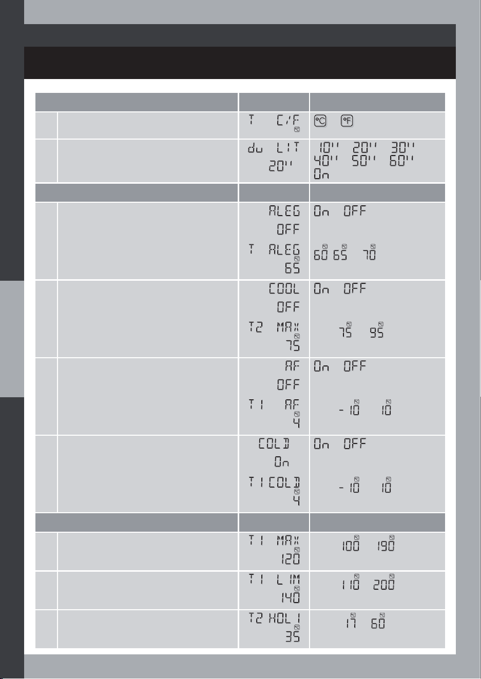
INSTALLER SET
SYST. 12
6HW&RQÀJ
Factory Setting Values
10 Degree unit
or
12 Display / light timeout
- -
- -
Optional function
Factory Setting Values
1 Anti-Legionella function
or
2 Anti-Legionella temperature threshold
, or
3 Cool System (safety function)
or
4 Maximum cylinder temperature (safety)
From to
5 Anti-Freeze function
or
6 Anti-Freeze temperature threshold
From to
7 Cold start function
or
8 Cold Start temperature threshold
From to
Expert Setting
Factory Setting Values
1 Maximum collector temperature
From to
2 Collector temperature safety limit
From to
3 Night temperature setpoint
(for HOLIDAYS mode)
From to
79
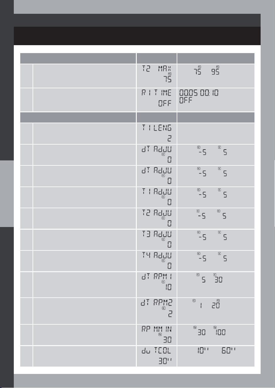
INSTALLER SET
SYST. 12
Expert Setting
Factory Setting Values
4 Maximum cylinder temperature (safety)
From to
5 Minimum pump-on duration
, or
Expert Setting Plus
Factory Setting Values
1 Length collector probe
2 Temperature difference zero adjustment
value
From to
3 Additional temperature difference zero
adjustment value
From to
4 T1 temperature zero adjustment value
From to
5 T2 temperature zero adjustment value
From to
6 T3 temperature zero adjustment value
From to
7 T4 temperature zero adjustment value
From to
8 Nominal temperature difference for
pump speed control
From to
9 Unit temperature difference for pump
speed control
From to
10 Minimum pump speed ratio
From to
11 Tube collector temperature test duration
(if TUBE type collector)
From to
80
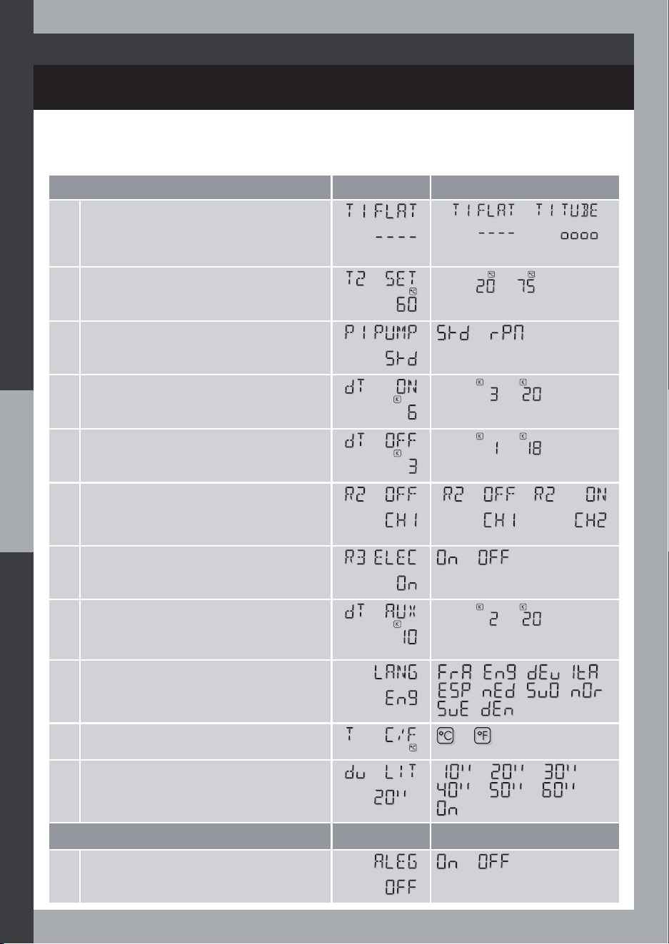
INSTALLER SET
SYST. 13
6HW&RQÀJ
Factory Setting Values
1 Collector Type
or
2 Cylinder temperature setpoint
From to
3 R1 output, R1 pump control, ON/OFF
mode (STD) bor speed variation mode
(RPM)
or
4 Temperature difference to switch on the
solar heating
From to
5 Temperature difference to switch off the
solar heating
From to
6 R2 output to valve, Valve way in idle
state
or
7 R3 output
or
8 Temperature difference (from the
temp. setpoint) for Auxiliary heating
authorization
From to
9 Language
- - -
- - -
-
10 Degree unit
or
11 Display / light timeout
- -
- -
Optional function
Factory Setting Values
1 Anti-Legionella function
or
81
SYSTEM 13: Solar system with 2-layer cylinder, 3-way Valve
and Electric auxiliary heating
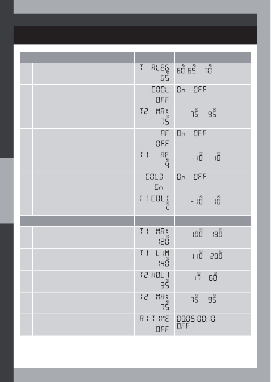
INSTALLER SET
SYST. 13
Optional function
Factory Setting Values
2
Anti-Legionella temperature threshold
, or
3 Cool System (safety function)
or
4 Maximum cylinder temperature (safety)
From to
5 Anti-Freeze function
or
6 Anti-Freeze temperature threshold
From to
7 Cold start function
or
8 Cold Start temperature threshold
From to
Expert Setting
Factory Setting Values
1 Maximum collector temperature
From to
2 Collector temperature safety limit
From to
3 Night temperature setpoint
(for HOLIDAYS mode)
From to
4 Maximum cylinder temperature (safety)
From to
5 Minimum pump-on duration
, or
82
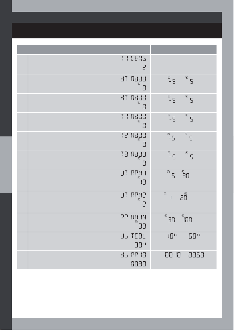
INSTALLER SET
SYST. 13
Expert Setting Plus
Factory Setting Values
1 Length collector probe
2 Temperature difference zero adjustment
value
From to
3 Additional Temperature difference zero
adjustment value
From to
4 T1 temperature zero adjustment value
From to
5 T2 temperature zero adjustment value
From to
6 T3 temperature zero adjustment value
From to
7 Nominal temperature difference for
pump speed control
From to
8 Unit temperature difference for pump
speed control
From to
9 Minimum pump speed ratio
From to
10 Tube collector temperature test duration
(if TUBE type collector)
From to
11 Storage cylinder loading test period
From to
83
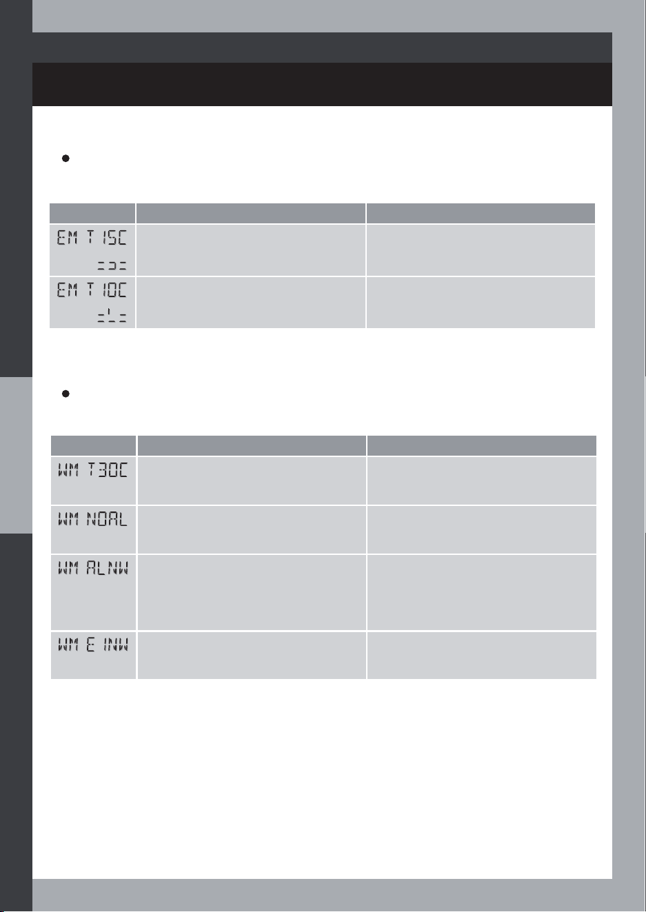
TROUBLESHOOTING
Warning messages
A WARNING (WM) signals a problem that does not prevent the system from operating.
Display Problem Troubleshooting
Open circuit at T3 disabling the
auxiliary heating
T3 probe missing
AL cannot run because no auxiliary
heating enabled
Enable the electric heating, select
a system with hydraulic heating or
disable the AL function
AL function does not work properly Check that the selected system
matches your installation, check the
correct setup of the electric and/
or hydraulic heating circuit (auxiliary
pump, boiler . . . )
E1 Not Working properly (on duration
shorter than 1 hour or period higher
than 72h)
Check the timeswitch connection
and working
Error messages
An ERROR (EM) signals a problem that does prevent the system from operating.
Display Problem Troubleshooting
Short-Circuit at T1 (T2, T3 or T4)
preventing the system from working
T1 (T2, T3, or T4) probe is faulty or
misconnected
Open-Circuit at T1 (T2, T3 or T4)
preventing the system from working
T1 (T2, T3, or T4) probe is missing or
faulty
84

PRODUCT RANGE AND ACCESSORIES
LEGAL GUARANTEE
Codes References
STASR001A Solar controller with 3 sensors PT1000
Codes References
STAPT15HTA Sensor for solar controller PT1000, high
temperature, 1,5m red cable
STAPT25NTA Sensor for solar controller PT1000, normal
temperature, 2,5m black cable
Accessories
Clause 1 – Warranty:
1.1 Scope: Products are guaranteed against all material and manufacturing defects for a period
of two years from the manufacturing date listed on each product. Acts undertaken under
the terms of the warranty shall not have the effect of extending the term thereof. During the
warranty period, the vendor undertakes to replace free of charge and in as short a timeframe
DVSRVVLEOHWKHSURGXFWVRUSDUWVZKLFKDUHGHIHFWLYHDQGWKXVXQÀWIRUWKHLULQWHQGHGXVH
After the vendor agrees to do so, the parts for repair or exchange shall be sent to the vendor’s
premises, under the care of and at the expense of the purchaser. They shall be delivered
(carriage paid) to the purchaser, who shall bear the assembly or disassembly costs of the
parts being repaired. Parts which are replaced shall remain the property of the vendor. The
replacement products and the repaired products are guaranteed under the same terms and
conditions as the original products, for an additional period of two years.
1.2 Exclusions: The warranty is not applicable if the purchaser cannot provide proof of full
payment for the supplies or if the installation and operating instructions supplied by the vendor
ZHUHQRWIROORZHGDQGOHVVVSHFLÀFDOO\LIWKHGDPDJHLQTXHVWLRQDULVHVRXWRIWKHDFWVRIWKH
purchaser or of its servants, out of force majeure or unforeseeable accidents. The warranty does
not apply in cases in which defects are due either to components provided by the purchaser,
or those defects which arise out of a design required by the purchaser, or if the product does
QRWIXOÀOREMHFWLYHVGHÀQHGE\WKHFOLHQWRIZKLFKWKHYHQGRUZDVQRWLQIRUPHG$Q\SRLQWVQRW
RXWOLQHGLQZULWLQJLQWKHOLVWRIVSHFLÀFDWLRQVRULQWKHRUGHUDUHQRWFRYHUHGE\WKHZDUUDQW\
Any and all damage due to normal wear and tear is also excluded.
85

TECHNICAL SPECIFICATIONS
Inputs / Outputs Description Name
4 temperature inputs PT1000 sensor type T1, T2, T3, T4
1 synchronization input Input driven by a free-voltage contact from
a time switch
(closed when low-tariff period running)
E1
Solar pump control output, rated load Semi-conductor 200W max, mains live
switch (0,1A min output current)
R1
2nd control output, rated load Relay 2A max, mains live switch R2
3rd control output, rated load Relay 1A max @ 250V, voltage-free R3
Power supply voltage 230-240V~, -10% +5%, 50Hz Mains
Environment Description
Safety Insulation: Class II,
Protection rating: IP20,
Pollution degree: 2,
Rated pulse voltage: 4KV
Operation temperature range 0 to +40°C
Storage temperature range -20°C to +70°C
Maximum humidity rate 85% RH non condensing @ 25°C
Standards EN60730-1
EN60730-2-9
Accessories Description Name
1 x High temperature probe
STAPT15HTA
PT1000 probe, -30°C to 200°C,
1,5 metres, red cord
T1 (T4)
2 x Standard temperature probe
STAPT25NTA
PT1000 probe, -15°C to 105°C,
2,5 metres, black cord
T2, T3 (T4)
Extension cable On request T1 (T4)
The symbol, on the product means that you must dispose of it at the
end of its life at a special recycling point, in accordance with the European
Directive WEEE 2002/96/EC. If you are replacing it, you can also return it to
the retailer from which you buy the replacement equipment. Indeed, the
product should not be disposed of with standard household waste. Recycling
products enables us to protect the environment and to use less natural resources.
Compliance declaration: we hereby declare under our sole responsibility that the products
described in these instructions comply with all the main requirements of the Low Voltage
2006/95/EC, CEM 2004/108/EC and RoHs 2011/65/EC directives and were manufactured
XVLQJSURFHVVHVZKLFKDUHFHUWLÀHG,62
86

NOTES
87

IMHOTEP création S.A.S. - 445 097 488 RCS Vienne - Siège social : Pont-Evêque
IMHOTEP création
®
ZI Montplaisir - Rue du Champ de Courses
38780 Pont-Evêque - France
Tél. : + 33 (0)4 74 58 39 56
Fax : + 33 (0)4 74 58 39 57
E-mail : [email protected]