
Loading ...
Loading ...
Loading ...
NORMA 4000/5000
Operators Manual
2-4
Electrical Connections
• Ensure that the power and connecting cables used with the device are in proper
working order.
• Ensure that the protective earth ground connector of the power lead is connected
according to the instructions of the low-resistance unit earth ground cable.
• Ensure that the power and connecting cables as well as all accessories used in
conjunction with the device are in proper working order and clean.
• Install the device in such a way that its power cable is accessible at all times and
can easily be disconnected.
• For connection work, work in teams of at least two persons.
• Do not use the device if the housing or an operating element is damaged.
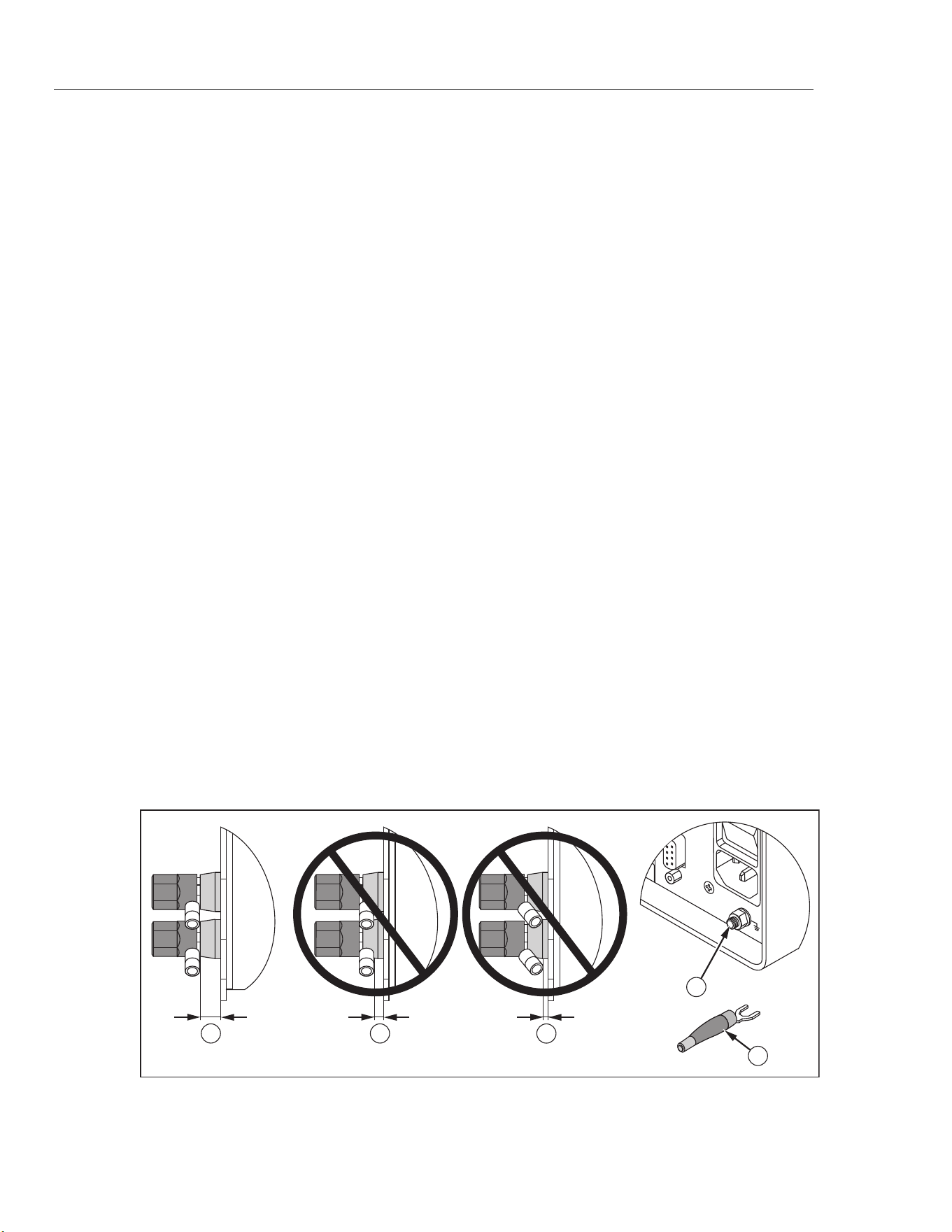
Binding Post
To maintain proper clearance distances, the lug must be correctly connected to the
connection terminal (binding post).
XW Warning
To avoid possible electric shock or personal injury from
flashover caused by CAT III transients between the housing and
the lug, see Figure 2-1:
• The minimum clearance distance must comply with at least
the distance illustrated in
.
• Do not reverse or bend the lug towards the housing.
• Use only insulated lugs preferably assembled with shrinking
tube as illustrated in
.
• If the connection leads exceed a cross section of 0.75 mm²,
an additional external-protective conductor with the same
cross section must be installed between the protective earth
terminal and the protective earth of the measuring circuit.
OK
1 2 3
SERIAL
5
4
esn070.eps
Figure 2-1. Binding Post Connection
1.888.610.7664 sales@GlobalTestSupply.com
Fluke-Direct.com
Loading ...
Loading ...
Loading ...