Loading ...

2
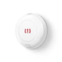
Ring Panic Button 2nd Gen
Introduction
The Ring Alarm Panic Button is a wireless sensor for the Ring Alarm system which provides users with
a single action emergency button. After configuring the device, Neighbors can trigger an emergency
response at the push of a button. The device is configurable in the Ring app to trigger either a Panic,
Medical or Fire alert. The Ring Alarm Base Station is required to enable Panic Button features and
functions within the Ring app.
1. This product can be operated in any Z-WaveTM network with other Z-Wave certified devices from
other manufacturers. All mains operated nodes within the network will act as repeaters regardless
of vendor to increase reliability of the network.
2. SmartStart enabled products can be added into a Z-Wave network by scanning the Z-Wave QR
Code present on the product with a controller providing SmartStart inclusion. No further action
is required and the SmartStart product will be added automatically within 10 minutes of being
switched on in the network vicinity.
Ring Alarm Panic Button Gen 2 – Basic Setup & Installation
1. Ensure your Ring Alarm system is disarmed.
2. In the Ring app, tap Set Up a Device and find the Panic Button in the Security Devices menu.
3. Follow the in-app instructions to complete setup.
a. Pull the battery tab (or reinsert the batteries) to trigger setup mode.
1. Tap the orange setup button to retry setup mode.
Installation
Once your Panic Button is set up in the Ring app, it’s ready to place on a table or shelf. It can also be
mounted to a wall, or discreetly under a desk or table.
Tape Mounting
Clean the mounting location, then peel the rubber pads o of the bottom cover to expose the
adhesive tape. Press the Panic Button firmly to the mounting location and hold for 20 seconds to make
sure the tape is securely attached.
Screw Mounting
You’ll need two flat head No. 4 x 5/8” (3mm x 15mm) screws and two No. 4 x 3/4” (5mm x 19mm)
wall anchors. Twist the bottom cover counterclockwise so that the unlock symbol is aligned with the
indicator. Pull to separate, then set the Panic Button aside. Drill pilot holes in the mounting surface using
a 3/16” (5mm) drill bit. Insert the wall anchors, then screw in the back cover. Place the Panic Button onto
the back cover and twist clockwise so that the lock symbol is aligned with the indicator. Check to make
sure it’s secure.
Loading ...
Loading ...
Loading ...