Serial Number
Decal
USER’S MANUAL
Model No. NTRW39124-INT.1
Serial No.
Write the serial number in the space
above for reference.
CAUTION
Read all precautions and
instructions in this manual before
using this equipment. Keep this
manual for future reference.
MEMBER CARE
UNITED KINGDOM
Website: iFITsupport.eu
E-mail: [email protected]
Write:
iFIT Health & Fitness Limited
Unit 4, Westgate Court
Silkwood Park
OSSETT
WF5 9TT
UNITED KINGDOM
AUSTRALIA
Call: 1800 993 770
E-mail: australiacc@iFIT.com
Write:
iFIT Inc.
PO Box 635
WINSTON HILLS NSW 2153
AUSTRALIA
iconeurope.com

2
TABLE OF CONTENTS
IMPORTANT PRECAUTIONS ..................................................................3
WARNING DECAL PLACEMENT . . . . . . . . . . . . . . . . . . . . . . . . . . . . . . . . . . . . . . . . . . . . . . . . . . . . . . . . . . . . . . .4
BEFORE YOU BEGIN. . . . . . . . . . . . . . . . . . . . . . . . . . . . . . . . . . . . . . . . . . . . . . . . . . . . . . . . . . . . . . . . . . . . . . . .5
PART IDENTIFICATION CHART. . . . . . . . . . . . . . . . . . . . . . . . . . . . . . . . . . . . . . . . . . . . . . . . . . . . . . . . . . . . . . . .6
ASSEMBLY . . . . . . . . . . . . . . . . . . . . . . . . . . . . . . . . . . . . . . . . . . . . . . . . . . . . . . . . . . . . . . . . . . . . . . . . . . . . . . . .7
HOW TO USE THE ROWER. . . . . . . . . . . . . . . . . . . . . . . . . . . . . . . . . . . . . . . . . . . . . . . . . . . . . . . . . . . . . . . . . .14
HOW TO USE THE CONSOLE. . . . . . . . . . . . . . . . . . . . . . . . . . . . . . . . . . . . . . . . . . . . . . . . . . . . . . . . . . . . . . . .16
MAINTENANCE AND TROUBLESHOOTING .....................................................23
EXERCISE GUIDELINES ....................................................................26
PART LIST. . . . . . . . . . . . . . . . . . . . . . . . . . . . . . . . . . . . . . . . . . . . . . . . . . . . . . . . . . . . . . . . . . . . . . . . . . . . . . . .28
EXPLODED DRAWING. . . . . . . . . . . . . . . . . . . . . . . . . . . . . . . . . . . . . . . . . . . . . . . . . . . . . . . . . . . . . . . . . . . . . .30
ORDERING REPLACEMENT PARTS .................................................. Back Cover
RECYCLING INFORMATION ......................................................... Back Cover
UK/EU DECLARATION OF CONFORMITY .............................................. Back Cover
NORDICTRACK and IFIT are registered trademarks of iFIT Inc. App Store is a trademark of Apple Inc., registered
in the U.S. and other countries. Android and Google Play are trademarks of Google LLC. The Bluetooth
®
word
mark and logos are registered trademarks of Bluetooth SIG, Inc. and are used under license. IOS is a trademark
or registered trademark of Cisco in the U.S. and other countries and is used under license.

3
IMPORTANT PRECAUTIONS
WARNING: To reduce the risk of serious injury, read all important precautions and
instructions in this manual and all warnings on the rower before using the rower. iFIT assumes
no responsibility for personal injury or property damage sustained by or through the use of this
product.
1. It is the responsibility of the owner to ensure
that all users of the rower are adequately
informed of all precautions.
2. Keep children under age 16 and pets away
from the rower at all times.
3. Consult your health care provider before
beginning any exercise program. This is
especially important for persons over age
35 or persons with pre-existing health
problems.
4. Consult your health care provider before
beginning or continuing any exercise pro-
gram during pregnancy. Use the rower only
as authorized by your health care provider.
5. The rower is not intended for use by persons
with reduced physical, sensory, or mental
capabilities or lack of experience and knowl-
edge, unless they are given supervision or
instruction about the use of the rower by
someone responsible for their safety.
6. Use the rower only as described in this
manual.
7. The rower is intended for home use only. Do
not use the rower in a commercial, rental, or
institutional setting.
8. Keep the rower indoors, away from moisture
and dust. Do not put the rower in a garage or
covered patio or near water.
9. Place the rower on a level surface, with a mat
beneath it to protect the floor or carpet. Make
sure that there is at least 2 ft. (0.6 m) of
clearance around the rower.
10. Inspect and properly tighten all parts each
time the rower is used. Replace any worn
parts immediately. Use only manufacturer-
supplied parts.
11. The rower should not be used by persons
weighing more than 250 lbs. (115 kg).
12. Wear appropriate clothes while exercising;
do not wear loose clothes that could become
caught on the rower. Always wear athletic
shoes for foot protection.
13. Always keep your back straight while using
the rower; do not arch your back.
14. Do not release the row bar while the strap is
extended.
15. Over exercising may result in serious injury
or death. If you feel faint, if you become short
of breath, or if you experience pain while
exercising, stop immediately and cool down.
4
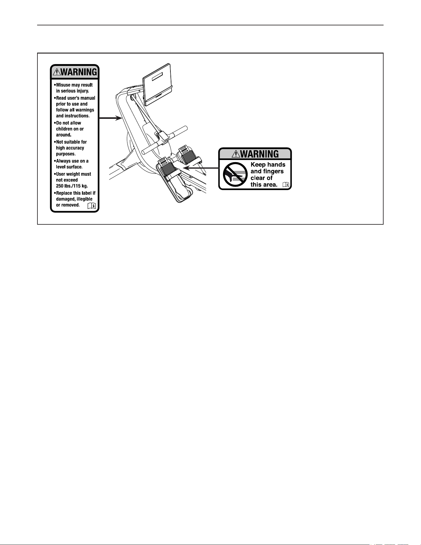
WARNING DECAL PLACEMENT
This drawing shows the location(s) of the warning
decal(s). If a decal is missing or illegible, see the front
cover of this manual and request a free replacement
decal. Apply the decal in the location shown. Note: The
decal(s) may not be shown at actual size.
5
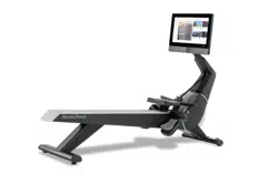
Thank you for selecting the new NORDICTRACK
®
RW 300 rower. Rowing is an effective exercise for
increasing cardiovascular fitness, building endurance,
and toning the body. The RW 300 rower is designed to
let you enjoy this effective exercise in the convenience
and privacy of your home.
For your benefit, read this manual carefully before
you use the rower. If you have questions after reading
this manual, please see the front cover of this manual.
To help us assist you, note the product model number
and serial number before contacting us. The model
number and the location of the serial number decal are
shown on the front cover of this manual.
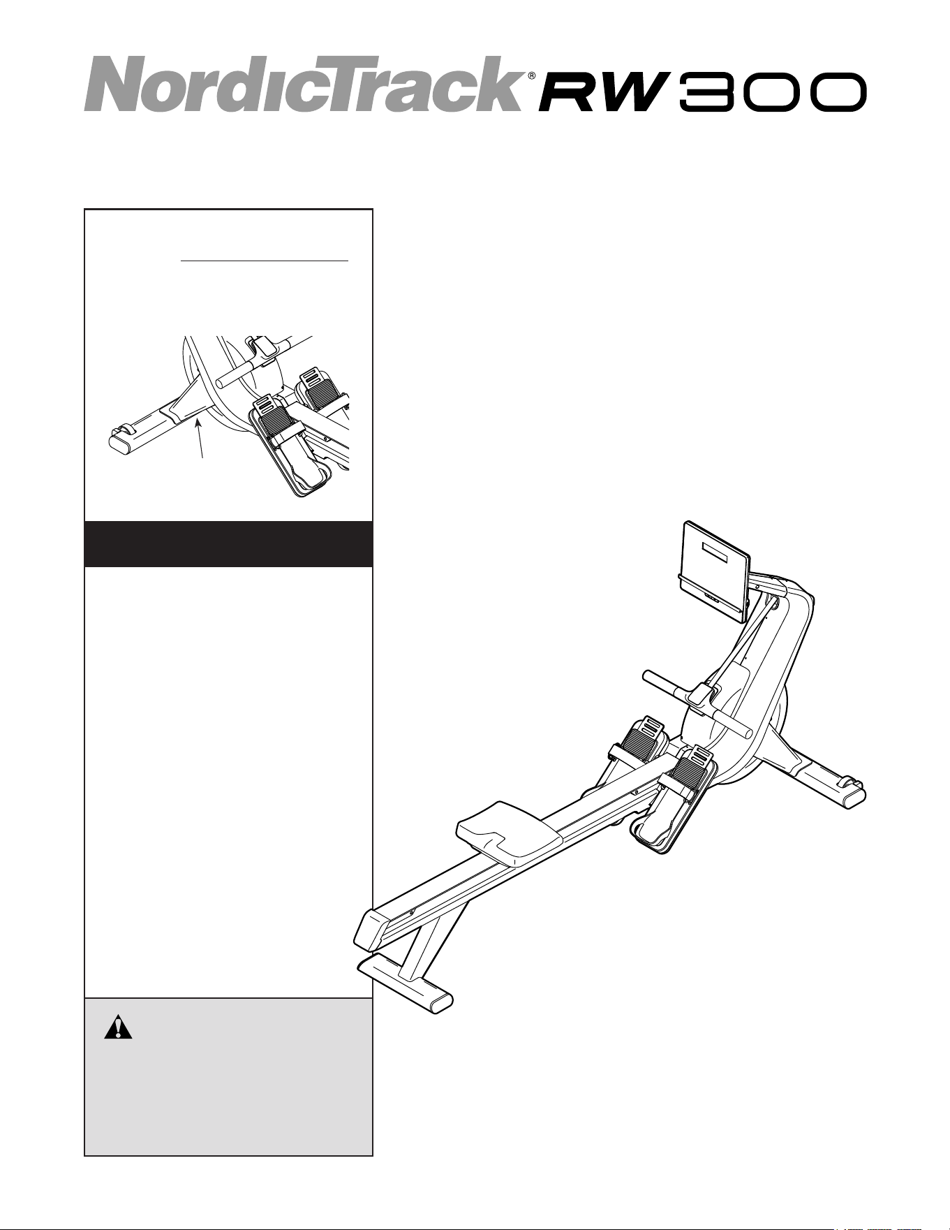
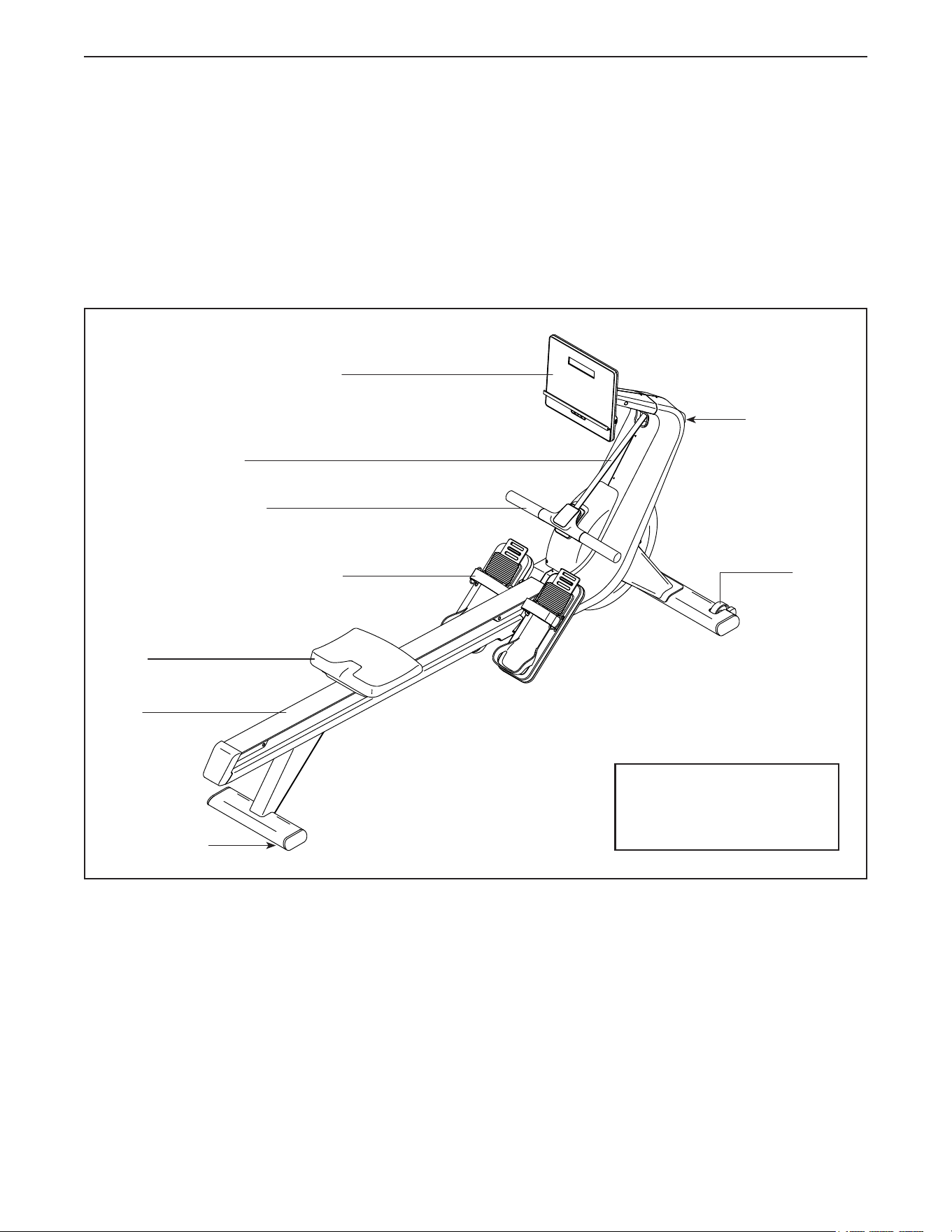
Before reading further, please review the drawing
below and familiarize yourself with the labeled parts.
Wheel
Adjustable Footrest
Seat
Rail
Leveling Foot
Row Bar
BEFORE YOU BEGIN
Strap
Adjustable Console
Length: 6 ft. 11 in. (210 cm)
Width: 2 ft. 1 in. (64 cm)
Weight: 129 lbs. (58 kg)
Storage Foot
6
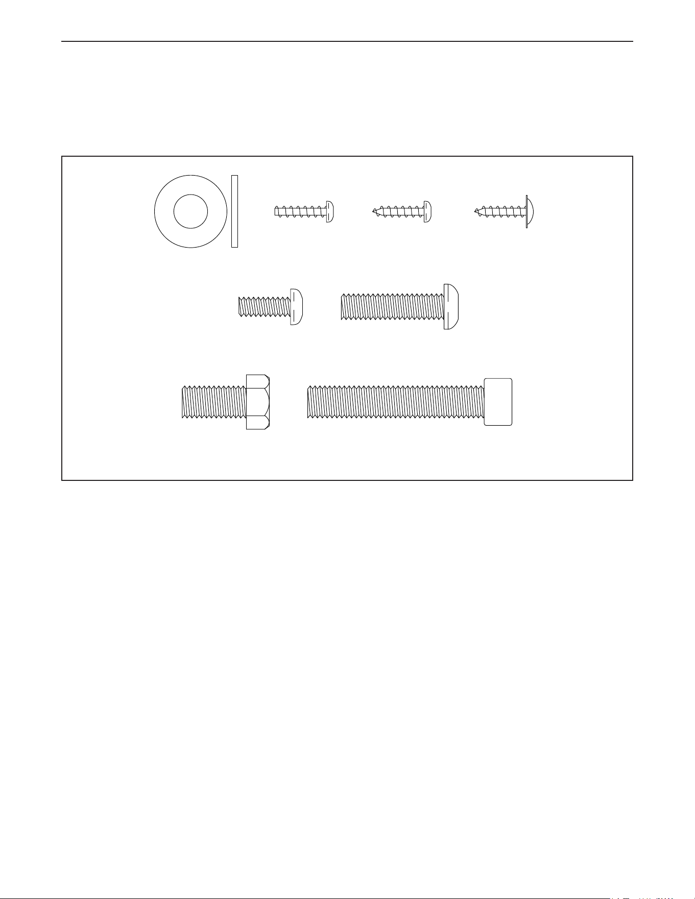
PART IDENTIFICATION CHART
Use the drawings below to identify the small parts needed for assembly. The number in parentheses below each
drawing is the key number of the part, from the PART LIST near the end of this manual. The number following
the key number is the quantity needed for assembly. Note: If a part is not in the hardware kit, check to see
whether it has been preassembled. Extra parts may be included.
M10 x 60mm Screw (103)–2
M8 x 32mm Screw
(125)–1
M6 x 16mm
Screw (126)–4
M4 x 16mm
Machine Screw
(104)–10
M10 Washer
(34)–6
M10 x 20mm
Screw (122)–8
M10 x 55mm Screw
(114)–3
M4 x 16mm
Screw (107)–4
M4 x 16mm
Washer Head
Screw (134)–4
7
• Assembly requires two persons.
• Place all parts in a cleared area and remove the
packing materials. Do not dispose of the packing
materials until you nish all assembly steps.
• To identify small parts, see page 6.
• Assembly can be completed using the included
tools. To avoid damaging parts, do not use power
tools for assembly.
Note: Keep the included tools. One or more of the
tools may be needed to make adjustments in the
future.
ASSEMBLY
1
1. To register your product and activate your
warranty in the UK, go to iFITsupport.eu. If you
do not have internet access, complete the war-
ranty registration card in the warranty booklet
and send it by registered post to the address on
the back cover of the warranty booklet.
To register your product and activate your
warranty in Australia, email or post the
following information to the email address or
postal address on the front cover of this manual.
• your receipt (make sure to keep a copy)
• your name, address, and telephone number
• the model number, serial number, and name
of your product (see the front cover of this
manual)
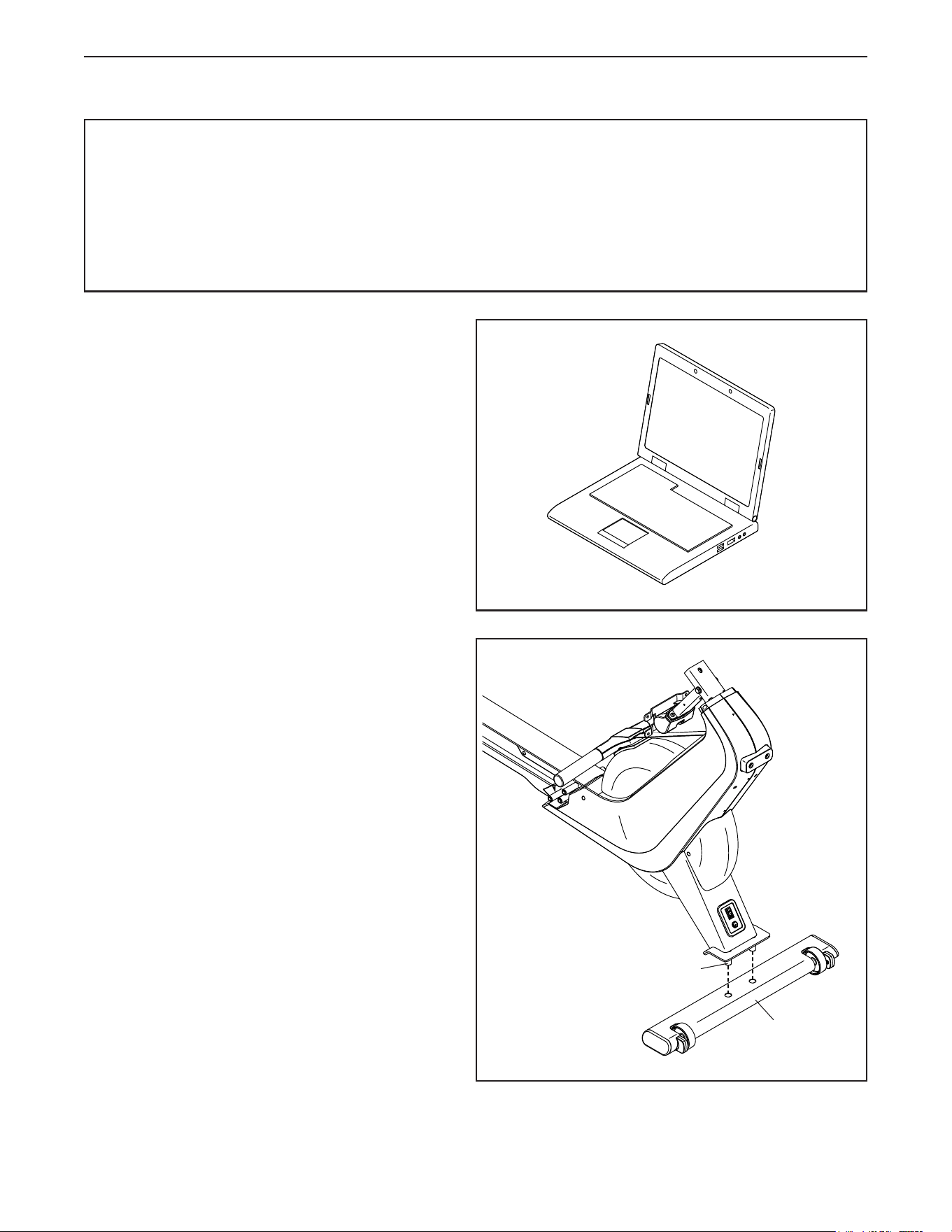
2. Orient the Stabilizer (4) as shown, and set it on
the floor in front of the rower.
Then, with the help of a second person, lift the
front of the rower and insert the two posts (A)
into the holes in the Stabilizer (4).
2
4
A
8
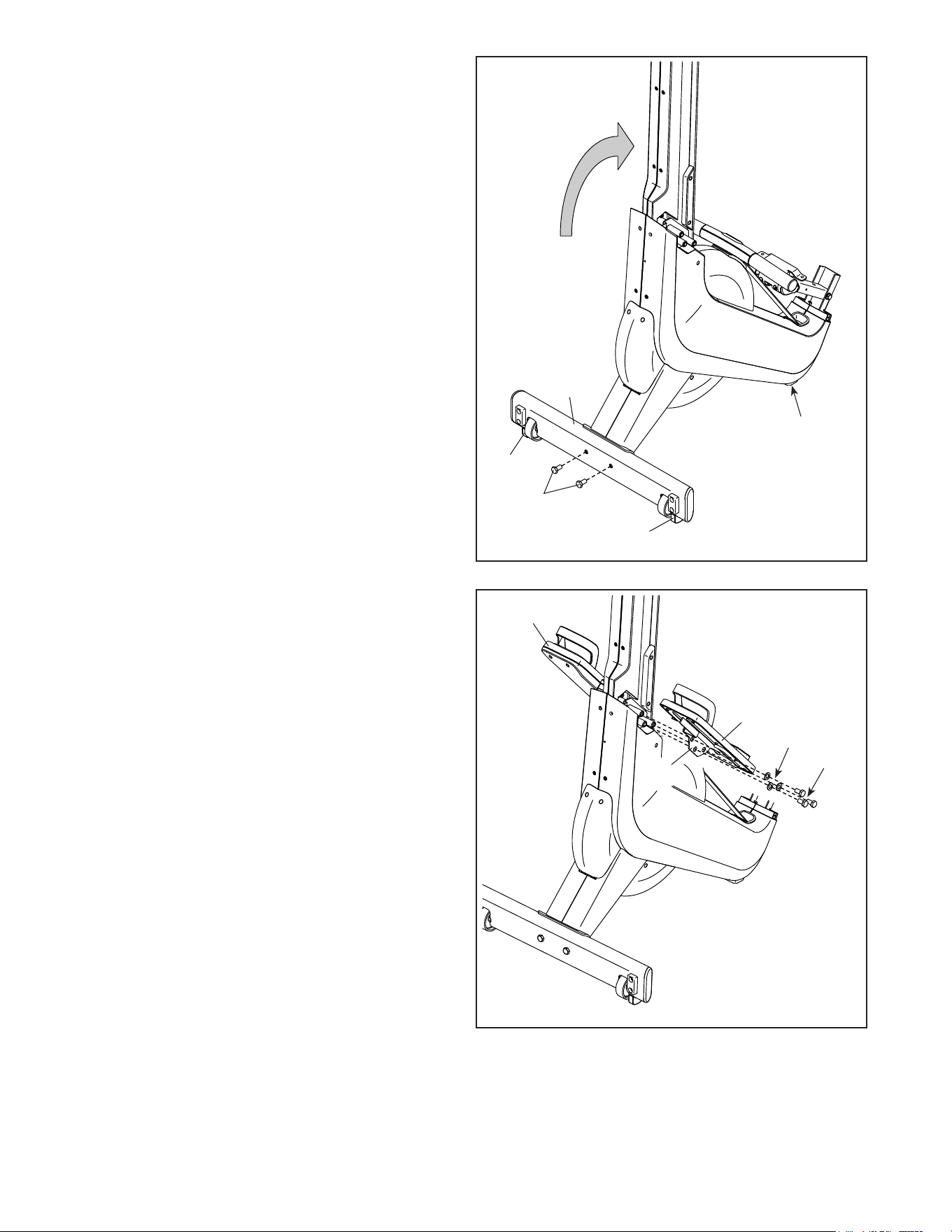
3. With the help of a second person, raise the
rower as shown until it is resting on the Large
and Small Storage Feet (12, 13). Make sure
that the Stabilizer (4) stays on the two posts
(not shown).
Then, attach the Stabilizer (4) with two M10 x
20mm Screws (122); start both Screws, and
then tighten them.
3
4. Identify the Right Footrest (29) and orient it as
shown.
Attach the Right Footrest Bracket (27) to the
right side of the rower with three M10 x 20mm
Screws (122) and three M10 Washers (34); start
all three Screws, and then tighten them.
Attach the Left Footrest (30) in the same way.
4
12
13
122
13
4
30
29
34
122
27
9
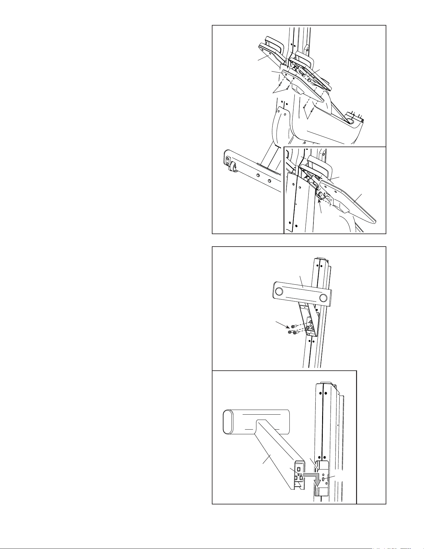
5. Identify the Right Footrest Bottom (31) and orient
it as shown.
See the inset drawing. Slide the Right Footrest
Bottom (31) under the Right Footrest Bracket
(27) so that the Right Footrest Bottom slides into
the indicated cutout (E).
Attach the Right Footrest Bottom (31) to the
Right Footrest Bracket (27) with four M4 x 16mm
Machine Screws (104); start all four Machine
Screws, and then tighten them.
Attach the Left Footrest Bottom (32) in the
same way.
5
6. See the inset drawing. Locate the indicated
pin (B) on the Rear Leg (5). Insert the pin into
the keyhole (C) in the rower Frame (1), and then
slide the Rear Leg downward until it stops. Make
sure that the pin is holding the Rear Leg in
place.
Then, attach the Rear Leg (5) with three
M10 x 55mm Screws (114); start all three
Screws, and then tighten them.
6
27
31
32
104
104
1
5
5
B
C
114
31
27
E
10
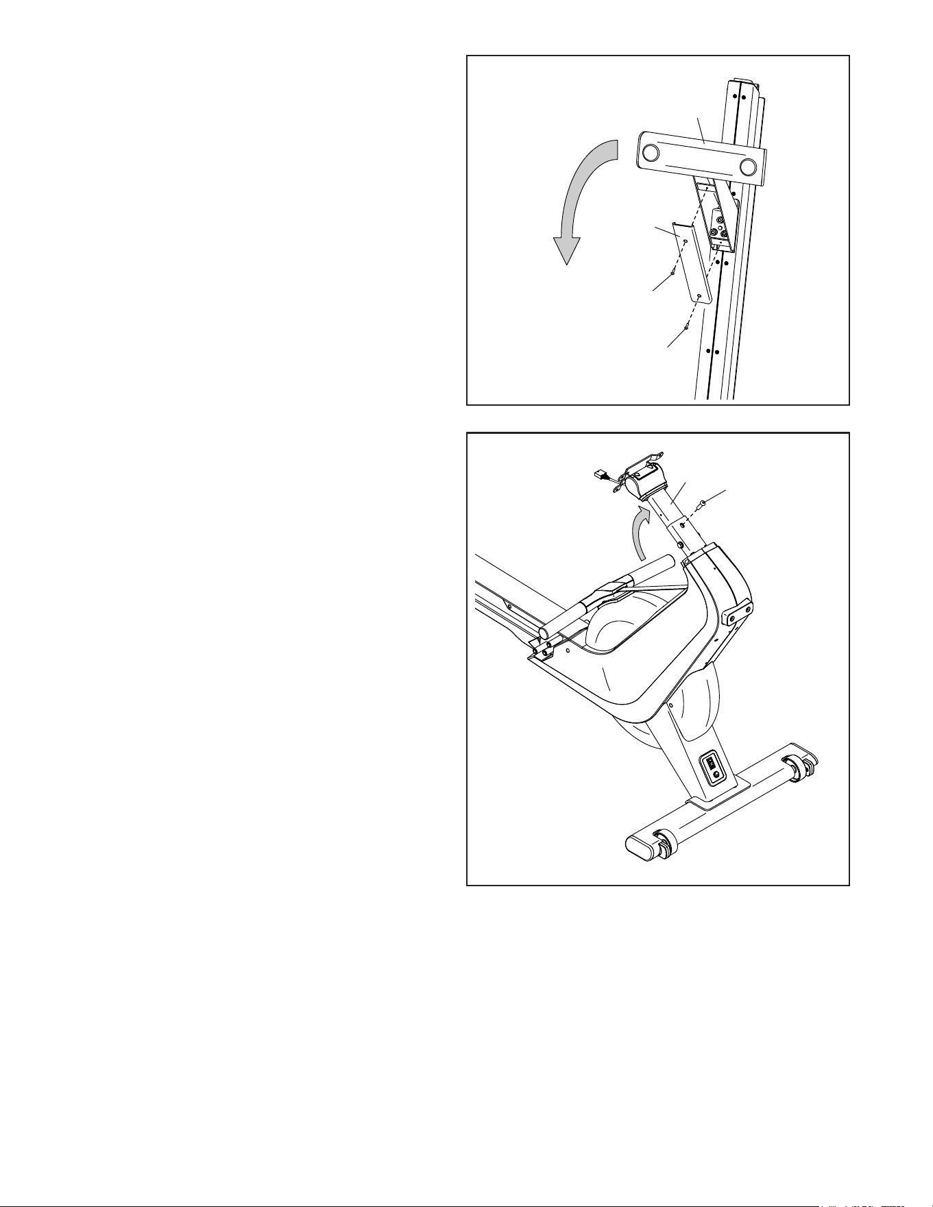
7. Attach the Rear Leg Cover (3) to the Rear Leg
(5) with two M4 x 16mm Screws (107).
Then, lower the rower so that the Rear Leg (5) is
resting on the floor.
7
8
3
107
107
8
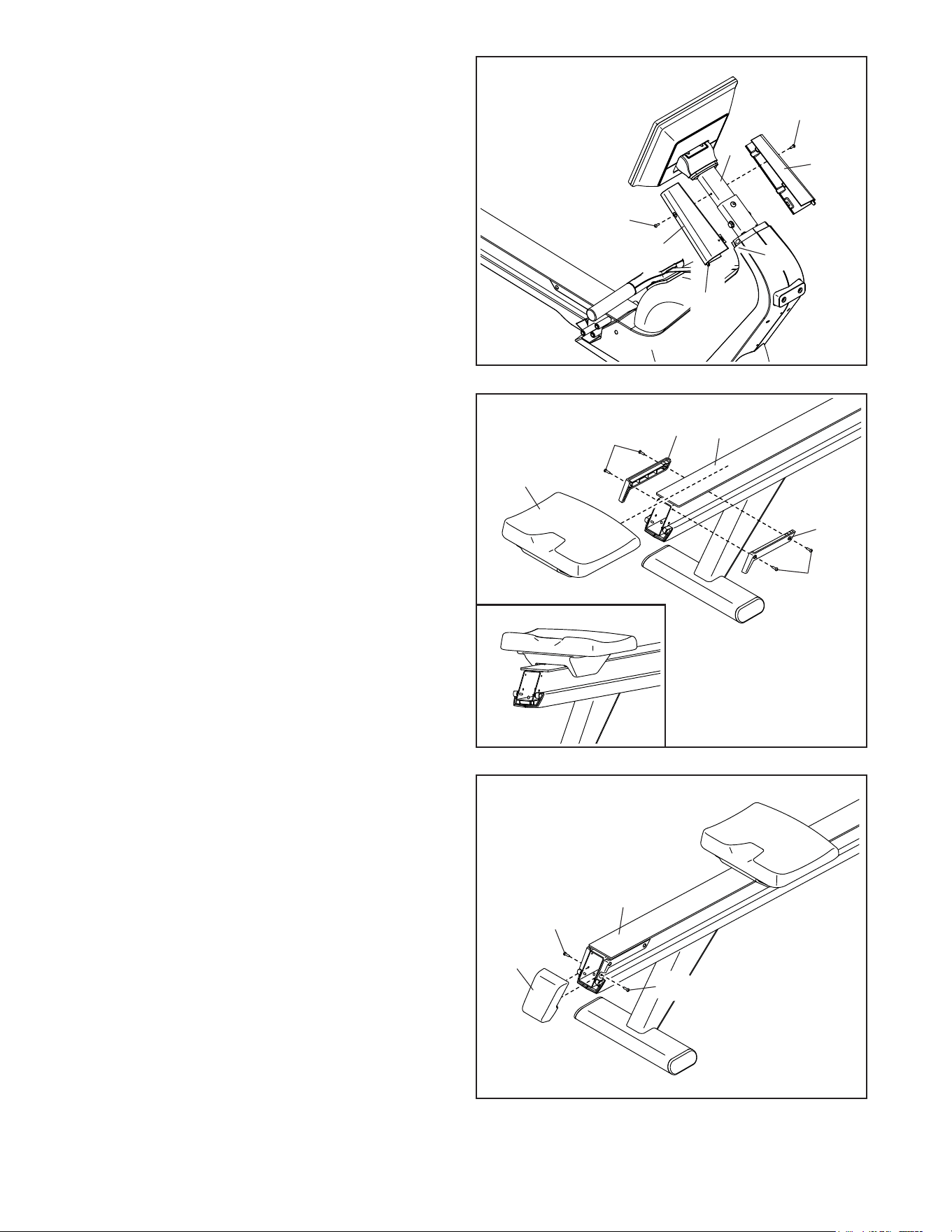
8. Pivot the Neck (8) upward to the position shown.
Secure the Neck with an M8 x 32mm Screw
(125).
5
125
11
9
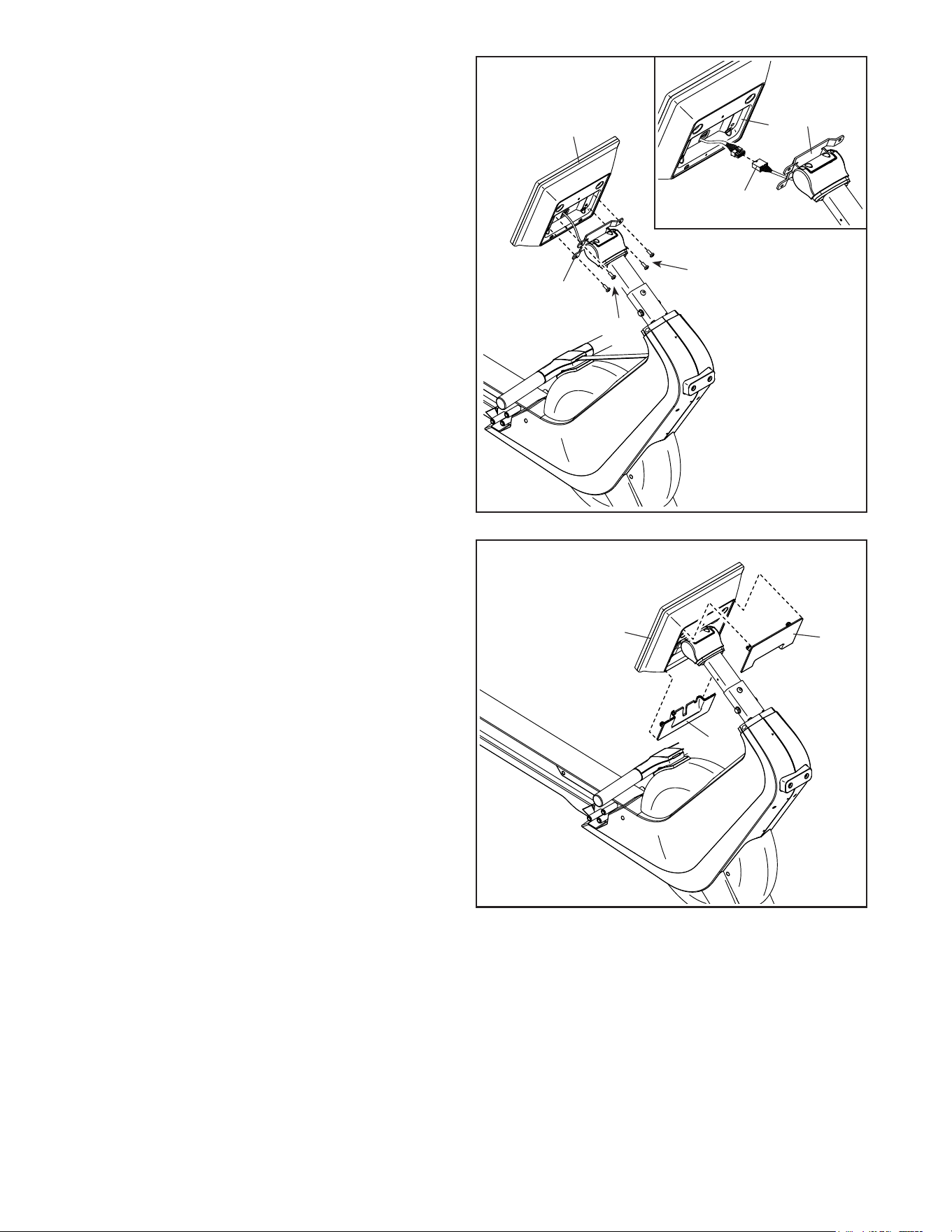
9. See the inset drawing. While a second person
holds the Console (6) near the Console Bracket
(7), connect the wire on the Console to the Main
Wire (92). IMPORTANT: The wire connectors
should slide together easily and snap into
place with an audible click. You must connect
the wires correctly for your rower to function
correctly.
Next, carefully insert the connectors on the wires
into the Console (6).
Avoid pinching the wires. Attach the Console
(6) to the Console Bracket (7) with four M6 x
16mm Screws (126); start all four Screws,
make sure that the Console (6) is level, and
then tighten the Screws.
10
10. Avoid pinching the wires during this step.
Identify the Console Lower Cover (23), which
is marked with a “1.” Press the Console Lower
Cover onto the back of the Console (6). Note:
It may be helpful to carefully hit the sides of the
Console Lower Cover with the heel of your hand
to snap it into place.
Then, press the Console Upper Cover (22) onto
the back of the Console (6).
2
92
23
22
126
126
7
7
6
6
Avoid pinching
the wires
Avoid pinching
the wires
6
12
12. Orient the Seat (36) as shown and slide it onto
the Frame (1).
Next, attach the Right Rear Stop (16) to the
Frame (1) with two M4 x 16mm Washer Head
Screws (134).
Attach the Left Rear Stop (17) in the same
way.
12
13. Press the Rail Cap (74) into the end of the
Frame (1). Attach the Rail Cap) with two
M4 x 16mm Screws (107).
13
17
1
36
134
16
1
74
107
107
134
11. Identify the Right Neck Shield (77) and orient it
as shown.
Next, insert the indicated tab (D) on the Right
Neck Shield (77) into the Right Shield (75), and
attach the Right Neck Shield to the Neck (8) with
an M4 x 16mm Machine Screw (104).
Attach the Left Neck Shield (78) in the same
way.
11
78
77
104
104
8
D
75
13
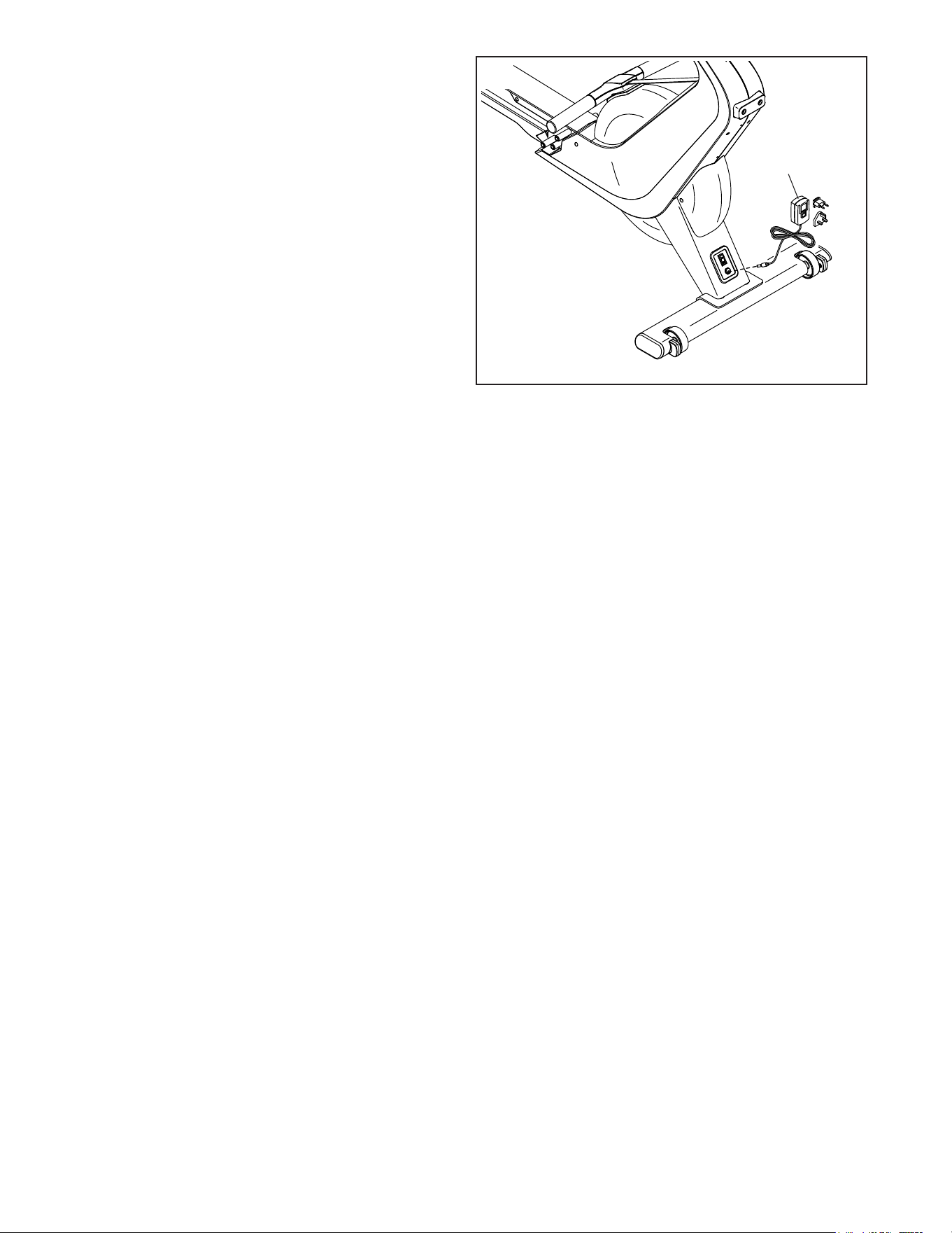
14. Plug the Power Adapter (82) into the receptacle
on the front of the rower.
Then, plug the Power Adapter (82) into an
outlet (see HOW TO PLUG IN THE POWER
ADAPTER on page 14).
82
14
15. Make sure that all parts are properly tightened before you use the rower. Place a mat under the rower to
protect the floor. Keep the included tools; one or more of the tools may be needed to make adjustments in the
future. Note: Extra hardware may be included.
14
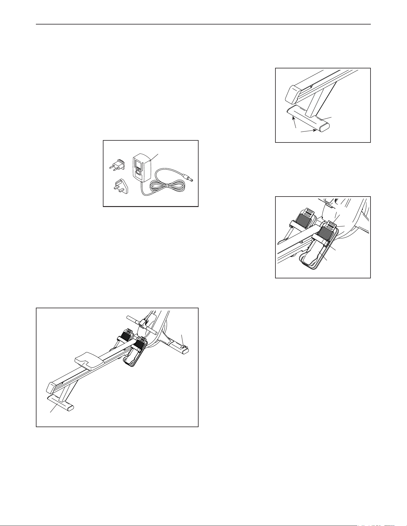
HOW TO PLUG IN THE POWER ADAPTER
IMPORTANT: If the rower has been exposed to cold
temperatures, allow it to warm to room temperature
before you plug in the power adapter (A). If you do
not do this, you may damage the console displays
or other electronic components.
IMPORTANT: Always plug the power adapter (A)
into the rower before you plug it into an outlet.
Make sure
that the power
adapter (A) is
plugged into the
receptacle on
the front of the
rower. Then, plug
the power adapter
into an appropri-
ate outlet that is
properly installed in accordance with all local codes
and ordinances.
HOW TO MOVE THE ROWER
Take any necessary measures to avoid damaging
your floor. Stand behind the rower and lift the rear
stabilizer (B) until the rower will roll on the wheels (C).
Carefully move the rower to the desired location, and
then lower it to the floor.
HOW TO LEVEL THE ROWER
If the rower rocks
slightly on your
floor during use,
turn one or both
of the leveling
feet (D) beneath
the rear stabi-
lizer (B) until the
rocking motion is
eliminated.
HOW TO ADJUST THE FOOTRESTS
First, sit on the seat and place your feet in the heel
brackets (E).
Next, lift the front
end of a heel
bracket (E), slide
the heel bracket
to the desired
position, and then
lower the front
end of the heel
bracket so that
the indicated tab
(F) engages one
of the slots in the
heel bracket. Then, tighten the strap (G) over your foot.
Adjust the other footrest in the same way. Make
sure that both heel brackets (E) are in the same
position.
A
B
C
B
D
HOW TO USE THE ROWER
G
E
F
E
15
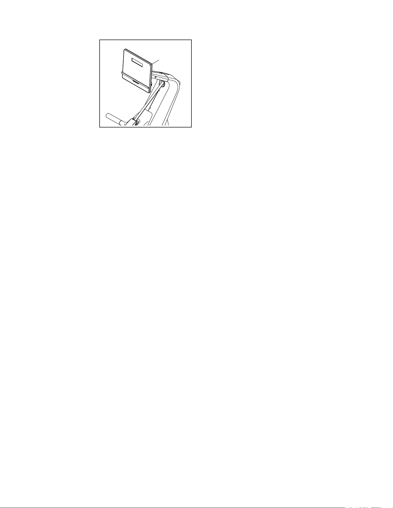
HOW TO ADJUST THE ANGLE OF THE CONSOLE
To adjust the
angle of the con-
sole (H), simply
hold the sides of
the console and
press it to the
desired position.
If the console
feels loose or
does not stay in
place when it is
tilted upward or
downward, see HOW TO ADJUST THE CONSOLE on
page 24.
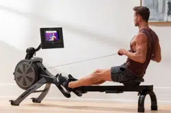
HOW TO ROW ON THE ROWER
Sit on the seat, place your feet in the footrests, and
adjust the straps to fit your feet. Then, hold the row bar
with an overhand grip.
Correct rowing form consists of three phases:
1. The first phase is the CATCH. Slide the seat
forward until your knees are almost touching your
chest. Pull the row bar until your hands are directly
above your feet.
2. The second phase is the DRIVE. Push backward
with your legs. Lean back slightly at the hips (not
at the waist), keeping your back straight. As you
straighten your legs, pull the row bar toward your
chest. Keep your elbows outward.
3. The third phase is the FINISH. Your legs should
be nearly straight. Continue to pull the row bar until
your hands are even with your chest.
After the finish phase, extend your arms forward and
pull the seat forward using your legs. Repeat this
sequence, moving through all three phases with a
smooth, fluid motion. Remember to breathe normally
as you row; never hold your breath.
H
16
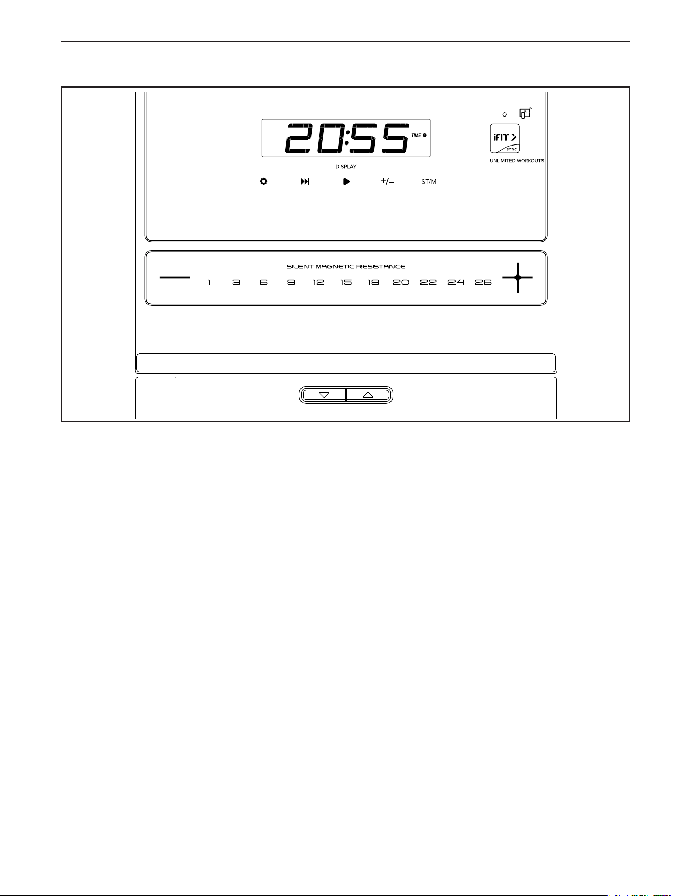
HOW TO USE THE CONSOLE
FEATURES OF THE CONSOLE
The advanced console offers an array of features
designed to make your workouts more effective and
enjoyable.
When you use the manual mode of the console, you
can adjust the resistance of the row bar with a touch
of a button. As you exercise, the console will display
continuous exercise feedback. You can even monitor
your heart rate using a compatible heart rate monitor.
See page 22 for information about a compatible
heart rate monitor.
The console also offers unlimited iFIT workouts when
you download the iFIT app to your smart device and
connect it to the console.
With the iFIT app, you can access a large and var-
ied library of iFIT video workouts, create your own
workouts, track your workout results, and access many
other features.
Each iFIT workout automatically changes the resis-
tance of the row bar as an iFIT coach guides you
through an immersive and effective video workout.
You can also use the console sound system while you
exercise.
To use the manual mode, see page 17. To use an
iFIT workout, see page 19. To change console set-
tings, see page 20.
To use the sound system, see page 21. To connect
your heart rate monitor to the console, see page 22.
Note: If there is a sheet of plastic on the display,
remove the plastic.
17
HOW TO USE THE MANUAL MODE
1. Turn on the console.
To turn on the console, press any button on the
console or simply begin rowing.
The displays will turn on and the console will be
ready for use.
2. Select the manual mode.
When you turn on the console, the manual mode
will be selected automatically.
3. Change the resistance of the row bar as
desired.
Begin rowing to start the manual mode.
As you row, you can change the resistance of the
row bar. To change the resistance, press one of the
numbered Silent Magnetic Resistance buttons or
press the Silent Magnetic Resistance increase and
decrease buttons.
Note: After you press a button, it will take a
moment for the rower to reach the selected
resistance level.
4. Follow your progress with the displays.
As you exercise, the following display modes will
provide instant exercise feedback:
Calories (CALS)—The approximate number of
calories you have burned.
Calories per Hour (CALS/HR)—The approximate
number of calories you are burning per hour.
Distance (M)—The distance that you have rowed
in meters or feet. To change the unit of measure-
ment, press the ST/M button
Pulse (BPM and heart symbol)—Your heart rate
when you use a compatible heart rate monitor (see
step 5).
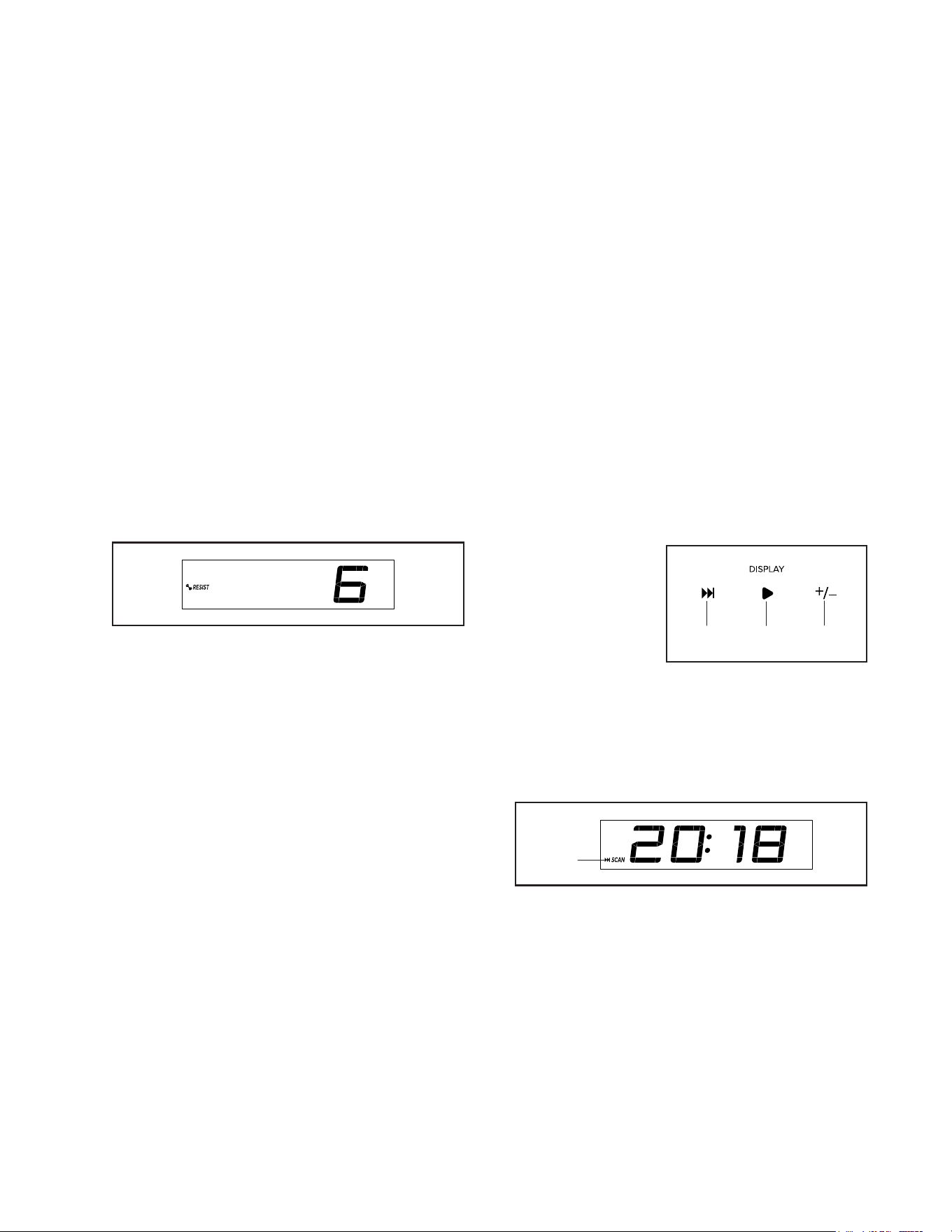
Resistance (RESIST)—The resistance level of the
row bar.
Strokes—This mode shows the number of rowing
strokes that you have completed.
Strokes Per Minute (STR/MIN)—This mode
shows the number of rowing strokes that you are
completing per minute.
Speed (KPH)—Your rowing pace in kilometers per
hour or miles per hour. To change the unit of mea-
surement, press the ST/M button.
Time—The elapsed time.
Watts—Your approximate power output in watts.
500 Meter Split (500 M SPLIT)—Your rowing pace
in the number of minutes that it takes to row 500
meters.
Press the Display
button (A) repeat-
edly to view the
desired workout
information in the
display.
Scan mode—The console also has a scan mode
that will display workout information in a repeating
cycle. To turn on the scan mode, press the Scan
button (B); the scan indicator (D) and the word
SCAN will turn on in the display.
To manually advance the scan cycle, press the
Scan button repeatedly.
To turn off the scan mode, press the Display
button (A); the scan indicator and the word SCAN
will turn off.
AB
C
D
18
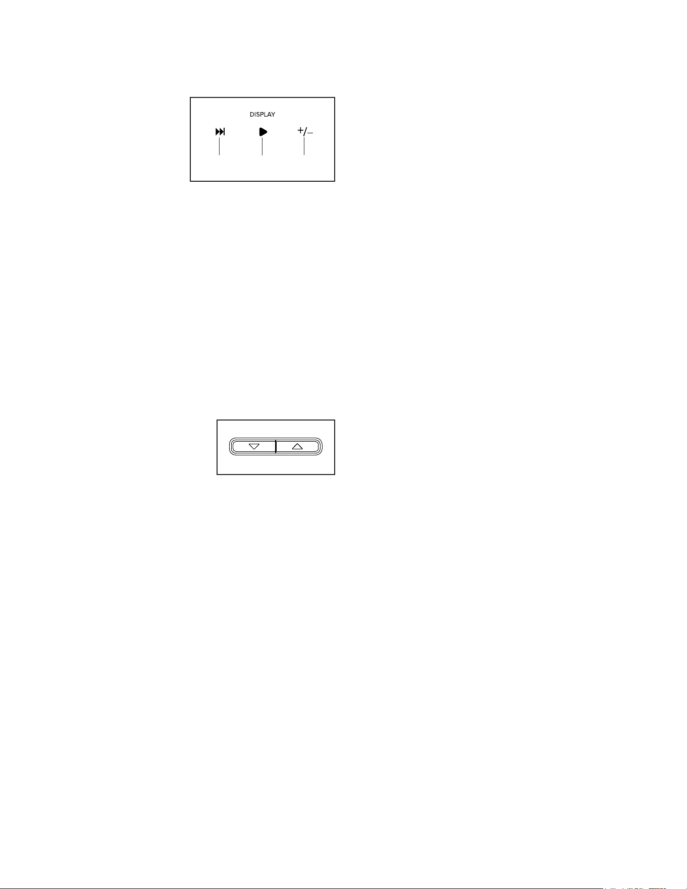
You can also customize the scan mode to display
only the desired workout information in the
repeating cycle.
To customize
the scan mode,
first press the
Display button
(A) repeatedly
until the workout
information that
you want to add
to or remove from the scan cycle appears in the
display.
Next, press the Add/Remove button (C) to add or
remove that workout information from the scan
cycle. When workout information is added, its
indicator will turn on in the display. When workout
information is removed, its indicator will turn off.
Then, press the Scan button (B) to turn on the scan
mode.
Note: The console will show your heart rate in the
scan cycle automatically whenever it detects a
pulse from a compatible heart rate monitor.
To change the volume
level of the console,
press the volume
increase and decrease
buttons.
To pause the console, simply stop rowing. When
the console is paused, the time will flash in the
display. To continue your workout, simply resume
rowing.
5. Wear a compatible heart rate monitor and
measure your heart rate if desired.
You can wear a compatible heart rate monitor to
monitor your heart rate while you exercise. Note:
The console is compatible with all Bluetooth
®
Smart
heart rate monitors. To purchase an optional
heart rate monitor, please see the front cover of
this manual.
To connect a compatible heart rate monitor to
the console, press the iFIT Sync button on the
console; the console pairing number will appear
in the display. When a connection is established,
the LED on the console will ash red twice. When
your heartbeat is detected, your heart rate will be
shown. See HOW TO CONNECT YOUR HEART
RATE MONITOR TO THE CONSOLE on page 22
for more information.
6. When you are finished exercising, the console
will turn off automatically.
If the row bar is not moved for a few seconds, the
console will pause.
The console has an auto-off feature. If the row
bar is not moved and the console buttons are not
pressed for a few minutes, the console will turn off
automatically.
Note: The console features a demo mode,
designed to be used if the rower is displayed in
a store. If the demo mode is turned on, the con-
sole will not turn off and the display will not be
reset when you nish exercising. To turn off the
demo mode, see HOW TO CHANGE CONSOLE
SETTINGS on page 20.
AB
C

19
HOW TO USE AN IFIT WORKOUT
The console offers access to a large and varied library
of iFIT workouts when you download the iFIT app to
your smart device and connect it to the console.
Note: The console supports Bluetooth connections to
smart devices via the iFIT app and to compatible heart
rate monitors. Other Bluetooth connections are not
supported.
1. Download and install the iFIT app on your
smart device.
On your iOS
®
or Android™ smart device, open the
App Store℠ or the Google Play™ store, search
for the free iFIT app, and then install the app on
your smart device. Make sure that the Bluetooth
option is enabled on your smart device.
Then, open the iFIT app and follow the instructions
to set up an iFIT account and customize settings.
Take time to explore the iFIT app and learn about
its features and settings.
2. Connect your heart rate monitor to the console
if desired.
If you are connecting both your heart rate monitor
and your smart device to the console, you must
connect your heart rate monitor before you
connect your smart device. See HOW TO
CONNECT YOUR HEART RATE MONITOR TO
THE CONSOLE on page 22.
3. Connect your smart device to the console.
Press the iFIT Sync button on the console; the
console pairing number will appear in the display.
Then, follow the instructions in the iFIT app to con-
nect your smart device to the console.
When a connection is established, the LED on the
console will turn solid blue.
4. Select an iFIT workout.
In the iFIT app, touch the buttons at the bottom of
the screen to select either the main menu (Home
button) or the workout library (Browse button).
To select a workout from the main menu or the
workout library, simply touch the desired workout
button on the screen. Slide or flick the screen to
scroll upward or downward if necessary.
When you select a workout, the screen will show
an overview of the workout that includes details
such as the duration and distance of the workout
and the approximate number of calories you will
burn during the workout.
5. Start the workout.
Touch Start Workout to start the workout.
During some workouts, an iFIT coach will guide
you through a video workout. Touch the sound but-
ton (music notes symbol) to select music, trainer
voice, and volume options for the workout.
During some workouts, the screen will show a map
of the route and a marker indicating your prog-
ress. Touch the buttons on the screen to select the
desired map options.
If the resistance setting for the current segment of
the workout is too high or too low, you can manu-
ally override the setting by pressing the Resistance
buttons on the console. IMPORTANT: When
the current segment ends, the resistance will
automatically adjust to the resistance setting
programmed for the next segment.
Note: The calorie goal shown in the workout
description is an estimate of the number of
calories that you will burn during the workout.
The actual number of calories that you burn
will depend on various factors, such as your
weight. In addition, if you manually change the
resistance level during the workout, the number
of calories you burn will be affected.
20
To pause the workout, simply touch the screen
or stop rowing. To continue the workout, simply
resume rowing.
To end the workout, touch the screen to pause the
workout, and then follow the prompts on the screen
to end the workout and return to the main menu.
When the workout ends, a workout summary will
appear on the screen. If desired, you can select
options such as adding the workout to your sched-
ule or adding the workout to your favorites list.
Then, touch Save Workout to return to the main
menu.
6. Disconnect your smart device from the
console.
To disconnect your smart device from the console,
first select the disconnect option in the iFIT app.
Then, press and hold the iFIT Sync button on the
console until the LED on the console turns solid
green.
Note: All Bluetooth connections between the
console and other devices (including any smart
devices, heart rate monitors, and so forth) will be
disconnected.
7. When you are finished exercising, the console
will turn off automatically.
If the row bar is not moved for a few seconds, the
console will pause.
The console has an auto-off feature. If the row
bar is not moved and the console buttons are not
pressed for a few minutes, the console will turn off
automatically.
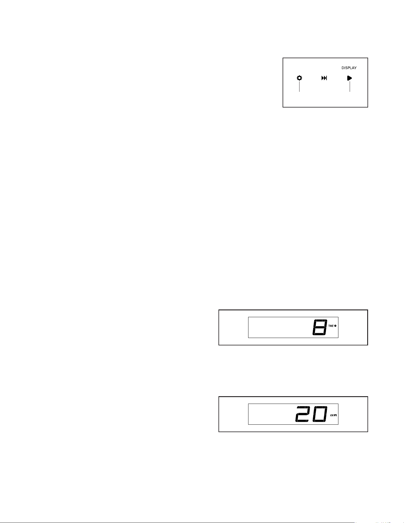
HOW TO CHANGE CONSOLE SETTINGS
1. Select the settings mode.
To select the set-
tings mode, press
the settings but-
ton (E). The first
settings screen
will appear in the
display.
2. Navigate the settings mode.
While the settings mode is selected, you can navi-
gate through several settings screens. Press the
Display button (A) repeatedly to select the desired
settings screen.
3. Change settings as desired.
Software Version Number—The software version
number will appear in the display.
Display Test—This screen is intended to be used
by service technicians to identify whether the
display is working correctly.
Button Test—This screen is intended to be used
by service technicians to identify whether a certain
button is working correctly.
Total Time—The word TIME will appear in the
display. The display will show the total number of
hours that the rower has been used.
Total Distance—The letters KM or MI will appear
in the display. The display will show the total
distance in kilometers or miles that the rower has
been rowed.
E
A
21
Contrast Level—The currently selected contrast
level will appear in the display. Press the Silent
Magnetic Resistance increase and decrease but-
tons to adjust the contrast level.
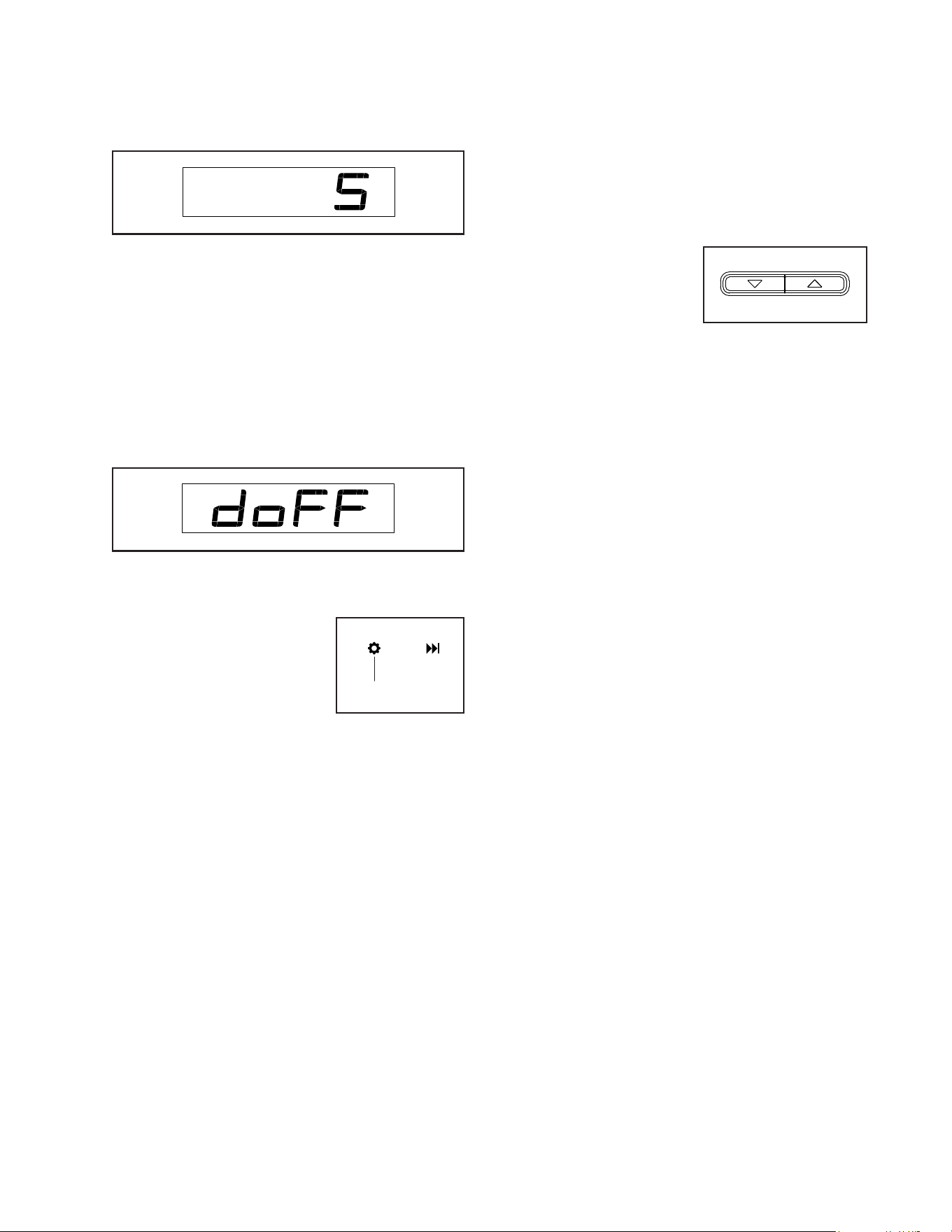
Demo Mode—The currently selected demo mode
option will appear in the display. The console
features a demo mode, designed to be used if the
rower is displayed in a store. If the demo mode
is turned on, the console will not turn off and the
display will not be reset when you nish exercis-
ing. Press the Silent Magnetic Resistance increase
button repeatedly to select a demo mode option. To
turn on the demo mode, select DON. To turn off the
demo mode, select DOFF.
4. Exit the settings mode.
To exit the settings mode,
Press the settings button (E).
HOW TO USE THE SOUND SYSTEM
To play music or audio books through the console
sound system while you exercise, plug a 3.5 mm male
to 3.5 mm male audio cable (not included) into the
jack on the right side of the console and into a jack on
your personal audio player; make sure that the audio
cable is fully plugged in. Note: To purchase an
audio cable, see your local electronics store.
Next, press the play button
on your personal audio
player. Adjust the volume
level using the volume
increase and decrease but-
tons on the console or the
volume control on your personal audio player.
E

22
THE OPTIONAL HEART RATE MONITOR
Whether your
goal is to
burn fat or to
strengthen your
cardiovascular
system, the key
to achieving the
best results is
to maintain the
proper heart
rate during your
workouts. The optional heart rate monitor will enable
you to continuously monitor your heart rate while you
exercise, helping you to reach your personal fitness
goals. To purchase an optional heart rate monitor,
please see the front cover of this manual.
Note: The console is compatible with all Bluetooth
Smart heart rate monitors.
HOW TO CONNECT YOUR HEART RATE MONITOR
TO THE CONSOLE
The console is compatible with all Bluetooth Smart
heart rate monitors.
To connect your Bluetooth Smart heart rate monitor to
the console, press the iFIT Sync button on the console;
the console pairing number will appear in the display.
When a connection is established, the LED on the
console will flash red twice.
Note: If there is more than one compatible heart rate
monitor near the console, the console will connect to
the heart rate monitor with the strongest signal.
To disconnect your heart rate monitor from the console,
press and hold the iFIT Sync button on the console
until the LED on the console turns solid green.
Note: All Bluetooth connections between the console
and other devices (including any smart devices, heart
rate monitors, and so forth) will be disconnected.
23
MAINTENANCE
Regular maintenance is important for optimal per-
formance and to reduce wear. Inspect and properly
tighten all parts each time the rower is used. Replace
any worn parts immediately. Use only manufacturer-
supplied parts.
To clean the rower, use a damp cloth and a small
amount of mild detergent. IMPORTANT: To avoid
damage to the console, keep liquids away from
the console and keep the console out of direct
sunlight.
RAIL MAINTENANCE
Regularly clean the rollers beneath the seat and the
area of the rail over which the rollers move. First,
see assembly steps 13 and 12 on page 12 and remove
the Rail Cap (74) and the Rear Stops (16, 17). Next,
roll the seat off the rail. Then, use a damp cloth and
a small amount of mild detergent to remove dust and
debris from the rollers and from the rail. Then, reattach
the parts that you removed.
TROUBLESHOOTING
Some problems can be solved with the simple
steps in this section. Find the symptom that
applies, and follow the steps listed. If further
assistance is needed, please see the front cover of
this manual.
CONSOLE TROUBLESHOOTING
If the console does not turn on, make sure that the
power adapter is fully plugged in.
If you are having problems connecting the console to
a wireless network, or if you are having problems with
your iFIT account or iFIT workouts, go to my.iFIT.com.
If a replacement power adapter is needed, please
see the front cover of this manual. IMPORTANT: To
avoid damaging the console, use only a manufac-
turer-supplied regulated power adapter.
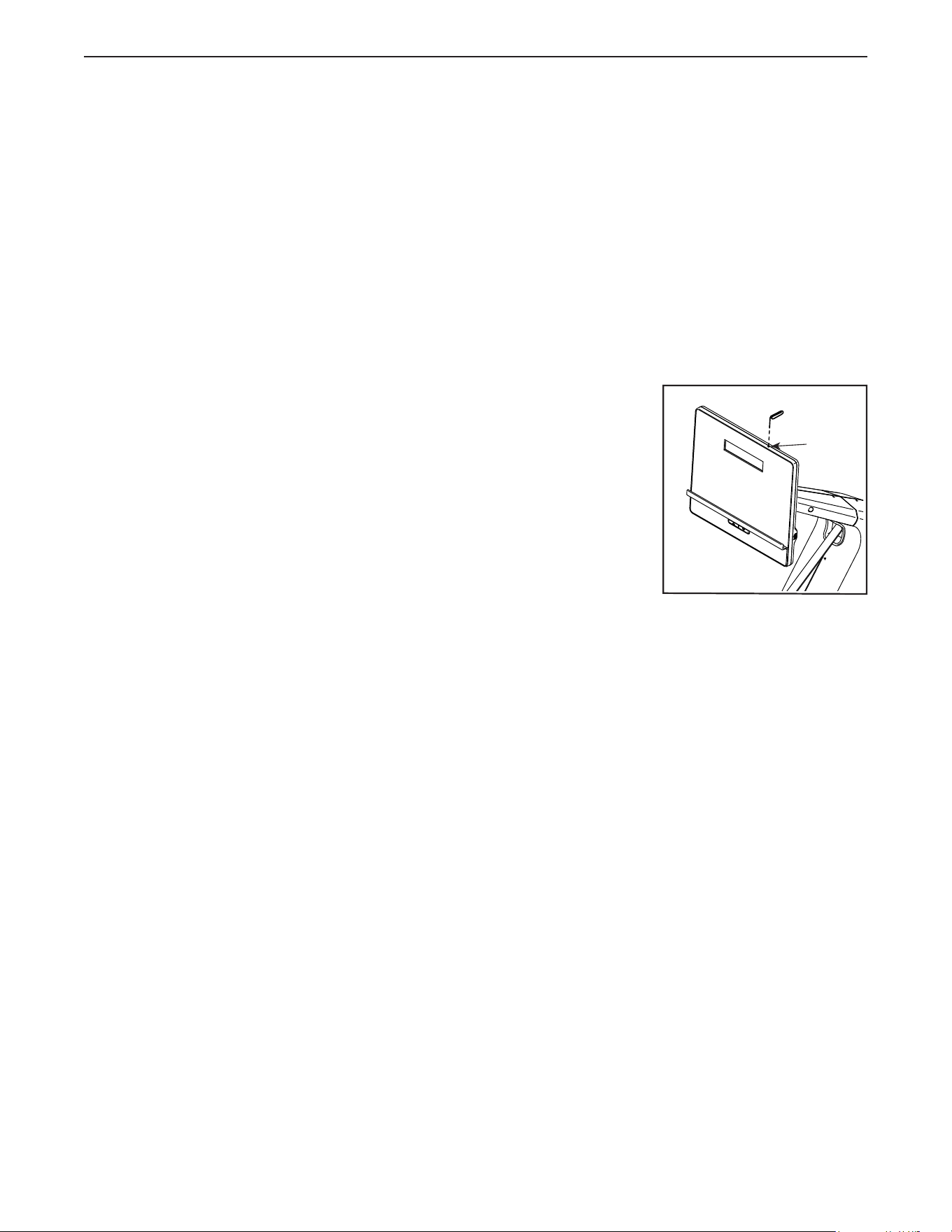
If the console does
not boot up prop-
erly, or if the console
freezes and does not
respond, reset the
console to the fac-
tory default settings.
IMPORTANT: Doing
this will erase all
custom settings you
have made to the
console. Resetting
the console requires
two people. First, unplug the power adapter. Next,
locate the small reset opening (A) on the top of the
console. Using a bent paper clip, press and hold the
reset button inside of the opening, and have a second
person plug in the power adapter. Continue holding the
reset button until the console turns on. When the reset
operation is complete, the console will turn off and then
turn back on. If it does not, unplug the power adapter
and then plug it back in. Once the console turns on,
check for rmware updates (see HOW TO CHANGE
CONSOLE SETTINGS on page 20). Note: It may take
up to a few minutes for the console to be ready for
use.
A
MAINTENANCE AND TROUBLESHOOTING
24
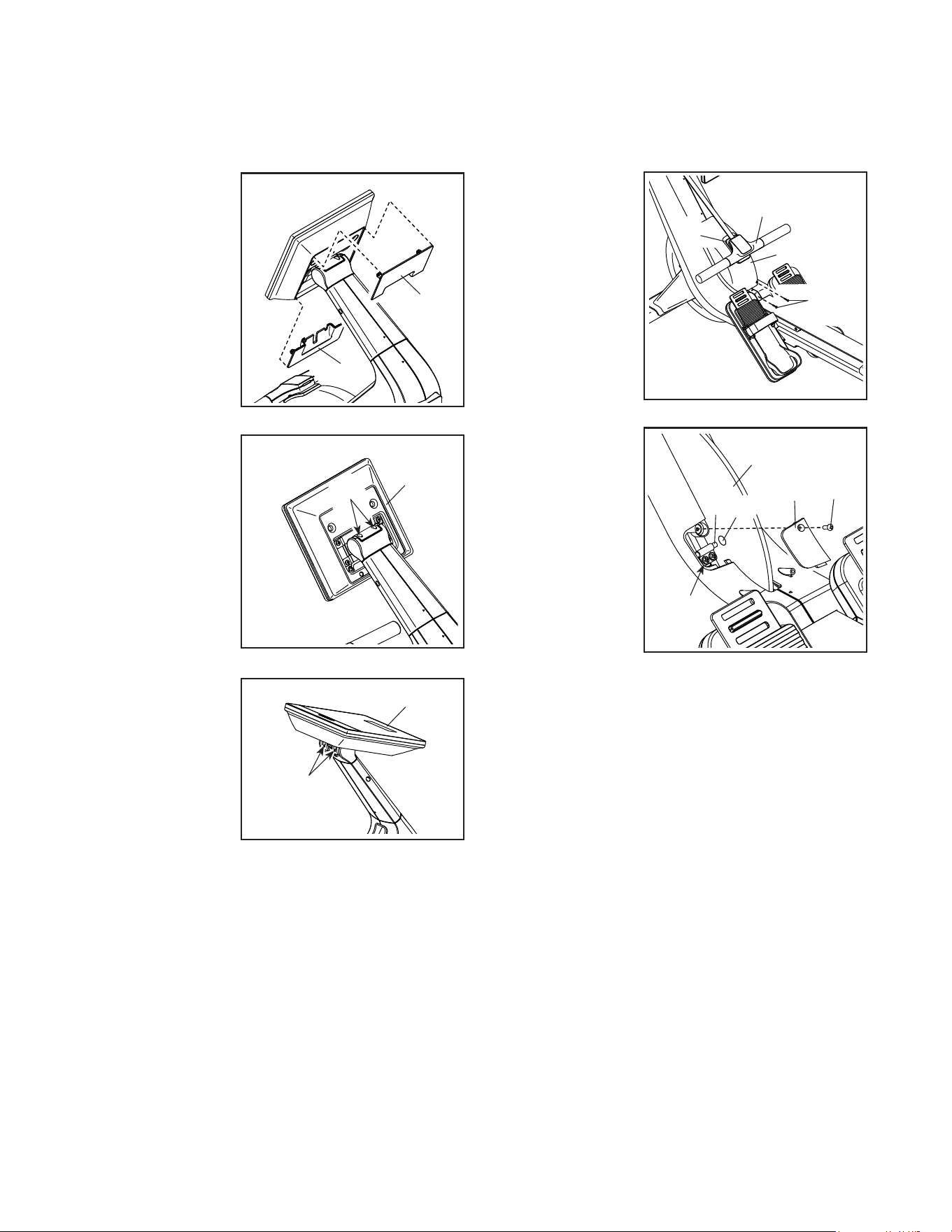
HOW TO ADJUST THE CONSOLE
If the console does not stay in place when it is tilted
upward and downward, first unplug the power
adapter (not shown).
Next, use a stan-
dard screwdriver
to carefully pry
off the Console
Upper Cover (22).
Then, pry off the
Console Lower
Cover (23).
Next, tilt the
Console (6) down-
ward as far as
possible. Tighten
the two indicated
M6 x 16mm
Socket Screws
(96) until the
upward and down-
ward movement
no longer feels
loose.
Then, tilt the
Console (6)
backward as
far as possible
and tighten the
two indicated
M6 x 16mm
Socket Screws
(96).
Then, reattach the Console Lower Cover (23) and the
Console Upper Cover (22).
HOW TO ADJUST THE REED SWITCH
If the console does not display correct feedback, the
reed switch should be adjusted. To adjust the reed
switch, first unplug the power adapter (not shown).
Next, remove
the Row Bar (19)
from the Row
Bar Hook (88).
Then, remove the
two M4 x 16mm
Screws (107), and
remove the Upper
Cover (85) from
the rower.
Next, remove the
M4 x 14mm Screw
(93), remove
the Access
Cover (86), and
locate the Reed
Switch (67). Turn
the Flywheel (60)
until a Flywheel
Magnet (81) is
aligned with the
Reed Switch.
Then, slightly
loosen the two
indicated M4 x 12mm Washer Head Screws (119),
slide the Reed Switch slightly closer to or away from
the Flywheel Magnet, and then retighten the Washer
Head Screws.
Plug in the power adapter, and turn the Flywheel (60)
so that the Flywheel Magnet (81) passes the Reed
Switch (67) repeatedly. Repeat the actions described
above until the console displays correct feedback.
When the reed switch is correctly adjusted, reattach
the parts that you removed.
22
23
6
96
6
96
107
85
19
88
60
86
93
67
119
81
25
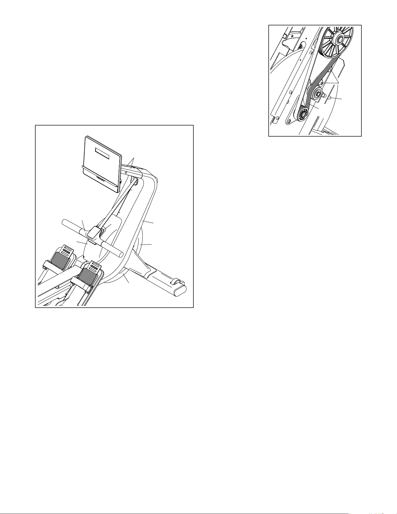
HOW TO ADJUST THE DRIVE BELT
If you feel the strap slip while you are rowing, even
when the resistance is adjusted to the highest level,
the drive belt may need to be adjusted. To adjust the
drive belt, first unplug the power adapter.
Next, see assembly step 11 on page 11. Remove the
Right and Left Neck Shields (77, 78).
Next, remove the Row Bar (19) from the Row Bar
Hook (88).
Then, remove the Upper Cover (85), the Front Cover
(79), the Lower Cover (80), and the Right Shield (75).
To locate the screws that attach each part, see
EXPLODED DRAWING B on page 31. Note: You will
need the help of a second person to tip the rower to
the side to access the lower Cover.
Next, locate the
Drive Belt (99)
on the right side
of the rower.
Loosen the two
M10 x 15mm
Screws (101).
Next, tighten the
M10 x 55mm Set
Screw (42) until
the Drive Belt
is tight. Then,
tighten the two
M10 x 15mm
Screws.
When the Drive Belt (99) is tight, reattach the parts that
you removed.
19
88
77, 78
75
79
80
85
42
99
101
26
These guidelines will help you to plan your exercise
program. For detailed exercise information, obtain a
reputable book or consult your physician. Remember,
proper nutrition and adequate rest are essential for
successful results.
EXERCISE INTENSITY
Whether your goal is to burn fat or to strengthen your
cardiovascular system, exercising at the proper inten-
sity is the key to achieving results. You can use your
heart rate as a guide to find the proper intensity level.
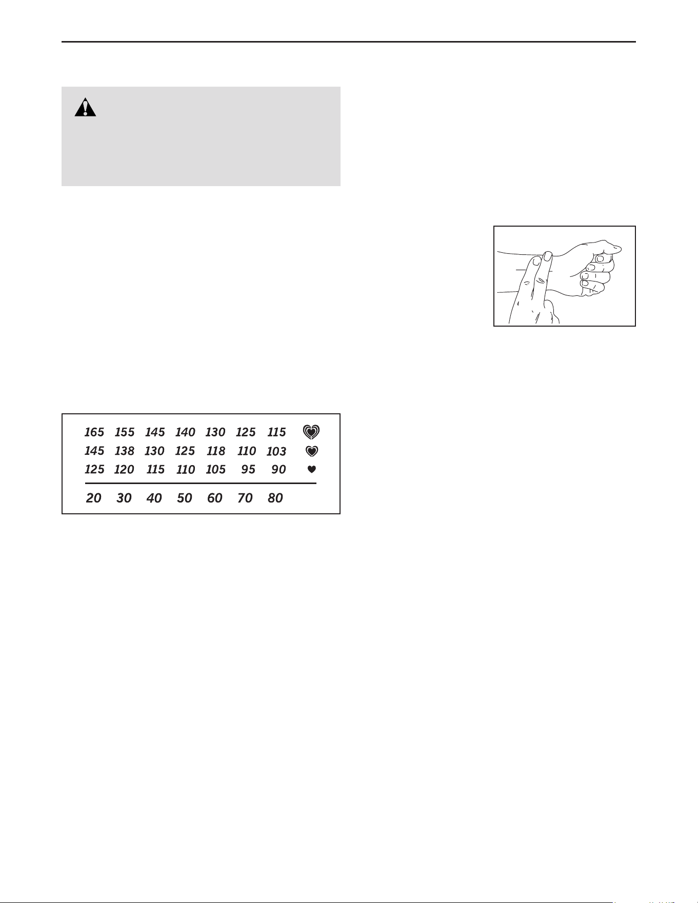
The chart below shows recommended heart rates for
fat burning and aerobic exercise.
To find the proper intensity level, find your age at the
bottom of the chart (ages are rounded off to the near-
est ten years). The three numbers listed above your
age define your “training zone.” The lowest number is
the heart rate for fat burning, the middle number is the
heart rate for maximum fat burning, and the highest
number is the heart rate for aerobic exercise.
Burning Fat—To burn fat effectively, you must exer-
cise at a low intensity level for a sustained period of
time. During the first few minutes of exercise, your
body uses carbohydrate calories for energy. Only
after the first few minutes of exercise does your body
begin to use stored fat calories for energy. If your
goal is to burn fat, adjust the intensity of your exer-
cise until your heart rate is near the lowest number in
your training zone. For maximum fat burning, exercise
with your heart rate near the middle number in your
training zone.
Aerobic Exercise—If your goal is to strengthen your
cardiovascular system, you must perform aerobic
exercise, which is activity that requires large amounts
of oxygen for prolonged periods of time. For aerobic
exercise, adjust the intensity of your exercise until
your heart rate is near the highest number in your
training zone.
HOW TO MEASURE YOUR HEART RATE
To measure your heart
rate, exercise for at
least four minutes.
Then, stop exercis-
ing and place two
fingers on your wrist
as shown. Take a
six-second heartbeat
count, and multiply the
result by 10 to find your heart rate. For example, if your
six-second heartbeat count is 14, your heart rate is 140
beats per minute.
WORKOUT GUIDELINES
Warming Up—Start with 5 to 10 minutes of stretch-
ing and light exercise. A warm-up increases your body
temperature, heart rate, and circulation in preparation
for exercise.
Training Zone Exercise—Exercise for 20 to 30 min-
utes with your heart rate in your training zone. (During
the first few weeks of your exercise program, do not
keep your heart rate in your training zone for longer
than 20 minutes.) Breathe regularly and deeply as you
exercise; never hold your breath.
Cooling Down—Finish with 5 to 10 minutes of stretch-
ing. Stretching increases the flexibility of your muscles
and helps to prevent post-exercise problems.
EXERCISE FREQUENCY
To maintain or improve your condition, complete
three workouts each week, with at least one day of
rest between workouts. After a few months of regular
exercise, you may complete up to five workouts each
week, if desired. Remember, the key to success is to
make exercise a regular and enjoyable part of your
everyday life.
WARNING: Before beginning this
or any exercise program, consult your physi-
cian. This is especially important for persons
over age 35 or persons with pre-existing
health problems.
EXERCISE GUIDELINES
27
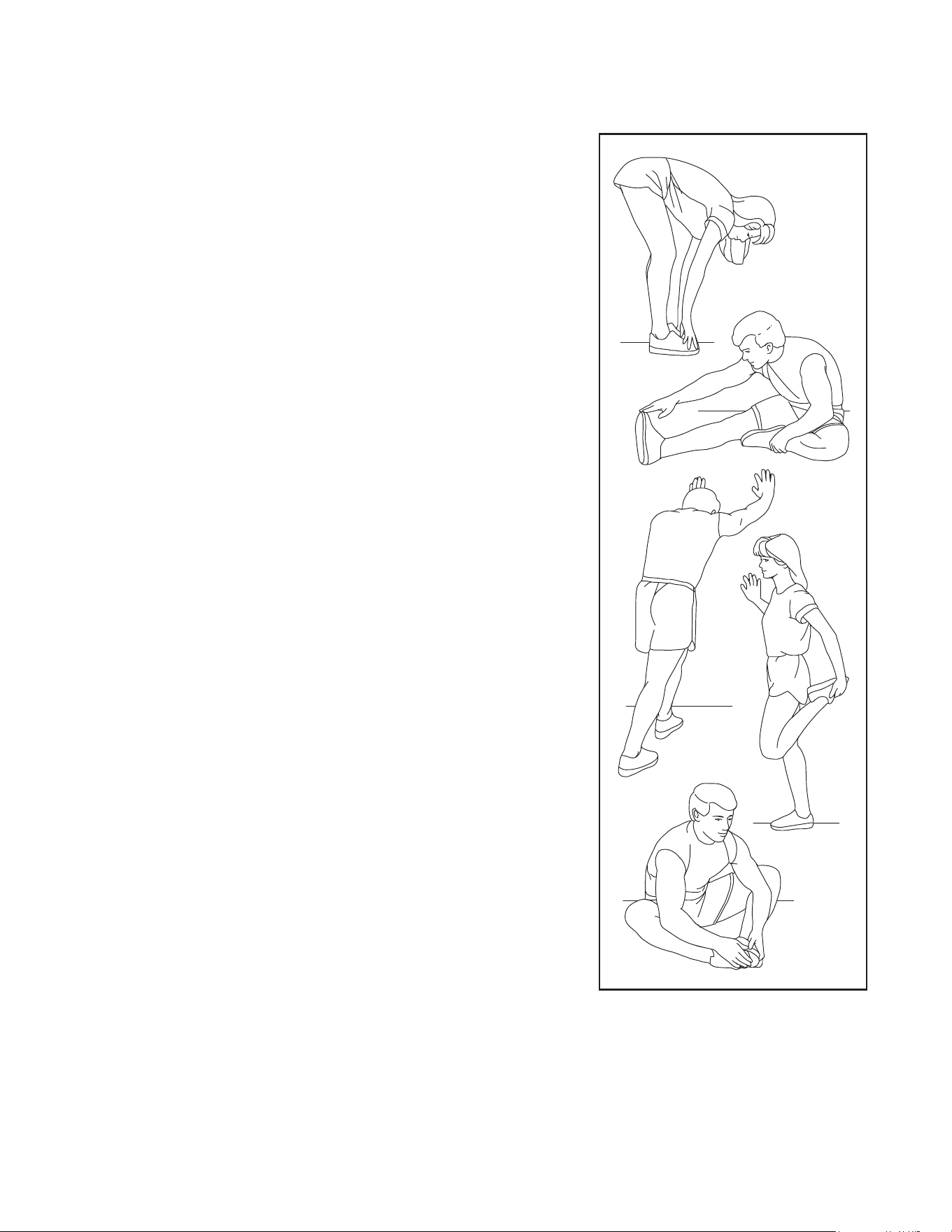
SUGGESTED STRETCHES
The correct form for several basic stretches is shown at the right. Move slowly as you stretch ; never bounce.
1. Toe Touch Stretch
Stand with your knees bent slightly and slowly bend forward from
your hips. Allow your back and shoulders to relax as you reach down
toward your toes as far as possible. Hold for 15 counts, then relax.
Repeat 3 times. Stretches: Hamstrings, back of knees and back.
2. Hamstring Stretch
Sit with one leg extended. Bring the sole of the opposite foot toward
you and rest it against the inner thigh of your extended leg. Reach
toward your toes as far as possible. Hold for 15 counts, then relax.
Repeat 3 times for each leg. Stretches: Hamstrings, lower back and
groin.
3. Calf/Achilles Stretch
With one leg in front of the other, reach forward and place your hands
against a wall. Keep your back leg straight and your back foot flat on
the floor. Bend your front leg, lean forward and move your hips toward
the wall. Hold for 15 counts, then relax. Repeat 3 times for each leg.
To cause further stretching of the achilles tendons, bend your back leg
as well. Stretches: Calves, achilles tendons and ankles.
4. Quadriceps Stretch
With one hand against a wall for balance, reach back and grasp one
foot with your other hand. Bring your heel as close to your buttocks as
possible. Hold for 15 counts, then relax. Repeat 3 times for each leg.
Stretches: Quadriceps and hip muscles.
5. Inner Thigh Stretch
Sit with the soles of your feet together and your knees outward. Pull
your feet toward your groin area as far as possible. Hold for 15 counts,
then relax. Repeat 3 times. Stretches: Quadriceps and hip muscles.
1
2
3
4
5

28
Key No. Qty. Description Key No. Qty. Description
1 1 Frame
2 1 Front Leg
3 1 Rear Leg Cover
4 1 Stabilizer
5 1 Rear Leg
6 1 Console
7 1 Console Bracket
8 1 Neck
9 1 Front Bracket Mount
10 1 Rear Bracket Mount
11 2 Inner Pivot Bushing
12 1 Large Storage Foot
13 2 Small Storage Foot
14 1 Carriage Cover
15 2 Front Stop
16 1 Right Rear Stop
17 1 Left Rear Stop
18 1 Strap
19 1 Row Bar
20 1 Row Bar Upper Cover
21 1 Row Bar Lower Cover
22 1 Console Upper Cover
23 1 Console Lower Cover
24 2 Leveling Foot
25 4 Stabilizer Cap
26 2 Wheel
27 1 Right Footrest Bracket
28 1 Left Footrest Bracket
29 1 Right Footrest
30 1 Left Footrest
31 1 Right Footrest Bottom
32 1 Left Footrest Bottom
33 2 Foot Bracket
34 6 M10 Washer
35 2 Footrest Strap
36 1 Seat
37 1 Carriage
38 2 Large Carriage Roller
39 2 Small Carriage Roller
40 2 Foot
41 1 Small Strap Guide Assembly
42 1 M10 x 55mm Set Screw
43 2 Frame Axle
44 1 Strap Roller
45 1 Return Pulley
46 1 Right Saddle Block
47 1 Left Saddle Block
48 1 Large Strap Guide
49 1 Return Pulley Spacer
50 1 Return Pulley Axle
51 1 Strap Guide Spacer
52 1 Snap Ring
53 1 Spring Bushing
54 1 Return Spring
55 1 Idler
56 1 Flywheel Pulley
57 2 Flywheel Saddle Block
58 2 Flywheel Bushing
59 1 Flywheel Hub
60 1 Flywheel
61 1 Frame Cover
62 1 Power Panel
63 1 Power Switch
64 1 Power Receptacle/Wire
65 1 Reed Switch Bracket
66 1 Reed Switch Clamp
67 1 Reed Switch/Wire
68 1 Magnet Bracket
69 1 Block
70 1 Arm
71 1 Motor Disc
72 1 Resistance Motor
73 1 Motor Bracket
74 1 Rail Cap
75 1 Right Shield
76 1 Left Shield
77 1 Right Neck Shield
78 1 Left Neck Shield
79 1 Front Cover
80 1 Lower Cover
81 2 Flywheel Magnet
82 1 Power Adapter
83 1 Strap Grommet
84 2 Roller Axle
85 1 Upper Cover
86 1 Access Cover
87 3 Zip Tie
88 1 Row Bar Hook
89 1 Right Rail Shield
90 1 Left Rail Shield
91 2 Clip Nut
92 1 Main Wire
93 7 M4 x 14mm Screw
94 1 Row Bar Tube
95 4 Crown Fastener
96 4 M6 x 15mm Socket Screw
97 4 M4 x 10mm Screw
98 2 M8 x 53mm Shoulder Screw
99 1 Drive Belt
100 2 M4 x 8mm Screw
PART LIST
Model No. NTRW39124-INT.1 R0723A

29
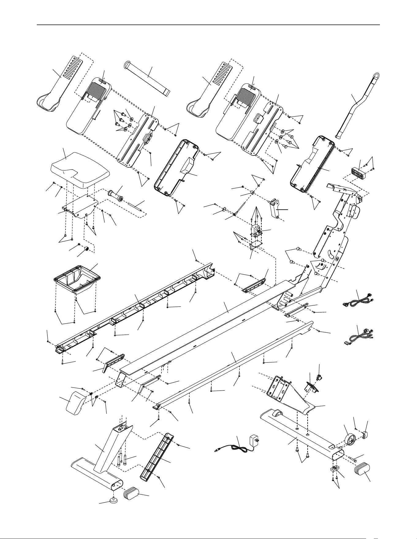
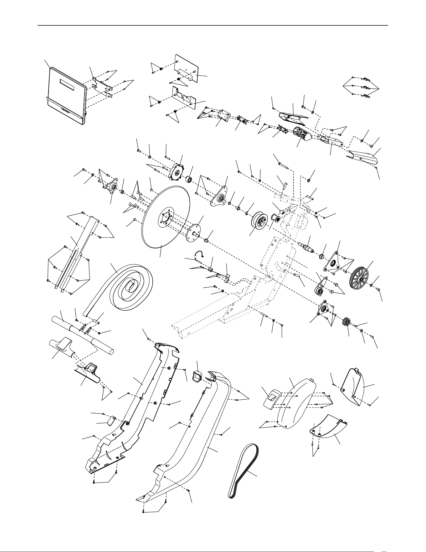
Note: Specications are subject to change without notice. For information about ordering replacement parts, see
the back cover of this manual. *These parts are not illustrated.
Key No. Qty. Description Key No. Qty. Description
101 2 M10 x 15mm Screw
102 10 M4 x 12mm Machine Screw
103 2 M6 x 20mm Screw
104 14 M4 x 16mm Machine Screw
105 11 M6 x 12mm Cap Screw
106 4 M10 x 25mm Screw
107 28 M4 x 16mm Screw
108 5 M10 x 16mm Flat Head Screw
109 1 M3 x 8mm Screw
110 9 M4 x 12mm Screw
111 2 M6 x 12mm Shoulder Screw
112 1 17mm C-clip
113 2 M5 Nut
114 3 M10 x 55mm Screw
115 2 M4 x 16mm Blunt Screw
116 8 M5 Washer
117 1 M5 x 8mm Screw
118 16 M6 x 12mm Screw
119 6 M4 x 12mm Washer Head Screw
120 12 M4 x 25mm Screw
121 1 M8 Locknut
122 8 M10 x 20mm Screw
123 2 M6 Locknut
124 8 M5 x 10mm Screw
125 1 M8 x 32mm Screw
126 4 M6 x 16mm Screw
127 1 Key
128 1 M8 x 65mm Bolt
129 5 M8 Washer
130 5 M8 x 16mm Screw
131 2 M6 x 10mm Shoulder Screw
132 3 M6 x 30mm Screw
133 2 M6 x 16mm Screw
134 8 M4 x 16mm Washer Head Screw
135 1 M6 Washer
* – User’s Manual
* – Assembly/Adjustment Tool Kit
30
EXPLODED DRAWING A
4
5
1
90
62
2
24
28
74
134
134
134
134
107
107
91
134
134
120
120
120
89
17
16
35
35
26
13
103
33
33
63
32
34
34
34
34
30
40
27
25
114
107
107
122
119
3
25
98
14
36
37
39
29
82
92
64
72
71
73
15
15
68
70
69
117
110
113
110
109
122
122
102
124
123
118
104
115
115
107
107
104
118
124
116
116
102
102
106
106
102
102
104
84
38
104
104
104
100
12
120
120
120
120
31
Model No. NTRW39124-INT.1 R0723A
31
EXPLODED DRAWING B
11
11
8
10
7
9
75
85
88
83
76
96
78
107
87
80
93
77
97
97
79
104
129
129
133
130
130
104
93
107
107
107
107
86
93
107
107
107
107
131
131
107
107
107
107
107
107
107
126
126
95
95
95
95
22
23
6
99
21
20
94
19
18
118
52
54
45
55
46
56
51
53
48
58
50
60
47
57
57
49
59
58
132
132
129
130
105
112
101
42
108
118
118
118
135
130
127
129
81
81
108
129
130
121
125
44
41
43
124
124
116
116
128
111
111
65
66
67
110
119
124
116
43
116
124
105
105
105
105
61
Model No. NTRW39124-INT.1 R0723A
Part No. 450899 R0723A Printed in China © 2023 iFIT Inc.
To order replacement parts, please see the front cover of this manual. To help us assist you, be prepared to
provide the following information when contacting us:
• the model number and serial number of the product (see the front cover of this manual)
• the name of the product (see the front cover of this manual)
• the key number and description of the replacement part(s) (see the PART LIST and the EXPLODED DRAWING
near the end of this manual)
ORDERING REPLACEMENT PARTS
This electronic product must not be disposed of in municipal waste. To
preserve the environment, this product must be recycled after its useful life
as required by law.
Please use recycling facilities that are authorized to collect this type of waste in
your area. In doing so, you will help to conserve natural resources and improve
European standards of environmental protection. If you require more information
about safe and correct disposal methods, please contact your local city office or
the establishment where you purchased this product.
RECYCLING INFORMATION
UK/EU DECLARATION OF CONFORMITY
NTRW39124-INT contains the BMD-ICN-1 Bluetooth module.
Hereby, iFIT Health & Fitness declares that the radio equipment type BMD-ICN-1 is in compliance with Directive
2014/53/EU and Radio Equipment Regulation 2017.
iFIT Health & Fitness, 1500 S 1000 W, Logan, UT 84320, USA
This declaration of conformity is issued under the sole responsibility of the manufacturer.
Object of the declaration: FCCID OMCBMD1 - Broadcast Frequency: 2.402GHz to 2.480GHz
Transmit Power: +4dBm
Certification: Article 3.1a - Safety EN 62479:2010, EN 62368-1:2014/AC:2015, Article 3.1b – EMC EN 301 489-17
V3.2.4, Article 3.2 – Radio parameters EN 300 328 V2.2.2
UK Representative: ICON Health & Fitness Ltd, Unit 1D The Gateway, Fryers Way, Silkwood Park, Ossett,
WF5 9TJ, United Kingdom
EU Representative: iFIT Health & Fitness SAS Business Park, 5 rue Alfred de Vigny
78112 Fourqueux, France