Hayward Industries
400 Connell Drive, Suite 6100
Berkeley Heights, NJ 07922
Phone: (908) 355-7995
www.hayward.com
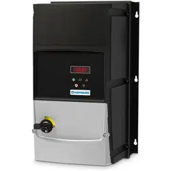
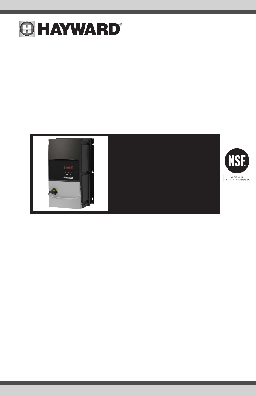
AC Variable Frequency Drive
Hayward Commercial Aquatics
Owner's Manual
2201051P
3201531P
Contents
Before you Begin...................3
Installation............................4
Operation............................10
Troubleshooting...................14
ISHCPVFD RevC
2201053P 4203003P
3201803P 4204603P
3202403P
460 Volt
Three-Phase Drives
208 - 230 Volt
Single-Phase Drives
208 - 230 Volt
Three-Phase Drive
1400413P 3401803P
2400583P 3402403P
2400953P 4403003P
3401403P 4403903P
4404603P
USE ONLY HAYWARD GENUINE REPLACEMENT PARTS
IMPORTANT SAFETY INSTRUCTIONS
When using this electrical equipment, basic safety precautions should always be followed, including the fol-
lowing:
READ AND FOLLOW ALL INSTRUCTIONS
WARNING: Follow all applicable electrical codes.
WARNING: Turn off power at main source before making any electrical connections or servicing the unit.
WARNING: To reduce the risk of electric shock, injury or death disconnect unit from power supply.
WARNING: Follow the instructions or risk of serious injury or death could occur!
WARNING - Read and follow all instructions in this owner’s manual and on the equipment. Failure
to follow instructions can cause severe injury and/or death.
WARNING – Suction Entrapment Hazard Suction in suction outlets and/or suction outlet covers
which are, damaged, broken, cracked, missing, or unsecured can cause severe injury and/or death
due to the following entrapment hazards:
Hair Entrapment- Hair can become entangled in suction outlet cover.
Limb Entrapment- A limb inserted into an opening of a suction outlet sump or suction outlet
cover that is damaged, broken, cracked, missing, or not securely attached can result in a mechani-
cal bind or swelling of the limb.
Body Suction Entrapment- A negative pressure applied to a large portion of the body or limbs can
result in an entrapment.
Evisceration/ Disembowelment - A negative pressure applied directly to the intestines through
an unprotected suction outlet sump or suction outlet cover which is, damaged, broken, cracked,
missing, or unsecured can result in evisceration/ disembowelment.
Mechanical Entrapment- There is potential for jewelry, swimsuit, hair decorations, finger, toe or
knuckle to be caught in an opening of a suction outlet cover resulting in mechanical entrapment.
WARNING - To Reduce the risk of Entrapment Hazards:
• When outlets are small enough to be blocked by a person, a minimum of two functioning
suction outlets per pump must be installed. Suction outlets in the same plane (i.e. floor or
wall), must be installed a minimum of three feet (3’) [1 meter] apart, as measured from near
point to near point.
• Dual suction fittings shall be placed in such locations and distances to avoid “dual blockage”
by a user.
• Dual suction fittings shall not be located on seating areas or on the backrest for such seating
areas.
• Never use Pool or Spa if any suction outlet component is damaged, broken, cracked, missing,
or not securely attached.
• Replace damaged, broken, cracked, missing, or not securely attached suction outlet compo-
nents immediately.
• Two or more suction outlets per pump installed in accordance with latest ASME, APSP Stan-
dards and CPSC guidelines, follow all National, State, and Local codes applicable.
• Installation of a vacuum release or vent system, which relieves entrapping suction, is recom-
mended.
WARNING – Failure to remove pressure test plugs and/or plugs used in winterization of the pool/
spa from the suction outlets can result in an increase potential for suction entrapment as described
above.
WARNING – Failure to keep suction outlet components clear of debris, such as leaves, dirt, hair,
paper and other material can result in an increase potential for suction entrapment as described
above.
1
USE ONLY HAYWARD GENUINE REPLACEMENT PARTS
WARNING – Suction outlet components have a finite life, the cover/grate should be inspected
frequently and replaced at least every ten years or if found to be damaged, broken, cracked, miss-
ing, or not securely attached.
CAUTION – Components such as the filtration system, pumps and heater must be positioned so
as to prevent their being used as means of access to the pool by young children. To reduce risk
of injury, do not permit children to use or climb on this product. Closely supervise children at all
times. Components such as the filtration system, pumps, and heaters must be positioned to pre-
vent children from using them as a means of access to the pool.
WARNING – Hazardous Pressure Pool and spa water circulation systems operate under hazard-
ous pressure during start up, normal operation, and after pump shut off. Stand clear of circulation
system equipment during pump start up. Failure to follow safety and operation instructions could
result in violent separation of the pump housing and cover, and/or filter housing and clamp due to
pressure in the system, which could cause property damage, severe personal injury, or death. Be-
fore servicing pool and spa water circulation system, all system and pump controls must be in off
position and filter manual air relief valve must be in open position. Before starting system pump,
all system valves must be set in a position to allow system water to return back to the pool. Do not
change filter control valve position while system pump is running. Before starting system pump,
fully open filter manual air relief valve. Do not close filter manual air relief valve until a steady
stream of water (not air or air and water) is discharged.
WARNING – Separation Hazard Failure to follow safety and operation instructions could result
in violent separation of pump and/or filter components. Strainer cover must be properly secured
to pump housing with strainer cover lock ring. Before servicing pool and spa circulation system,
filters manual air relief valve must be in open position. Do not operate pool and spa circulation
system if a system component is not assembled properly, damaged, or missing. Do not operate
pool and spa circulation system unless filter manual air relief valve body is in locked position in
filter upper body. Never operate or test the circulation system at more than 50 PSI. Do not purge
the system with compressed air. Purging the system with compressed air can cause components
to explode, with risk of severe injury or death to anyone nearby. Use only a low pressure (below 5
PSI), high volume blower when air purging the pump, filter, or piping.
WARNING – Risk of Electric Shock All electrical wiring MUST be in conformance with applicable
local codes, regulations, and the National Electric Code (NEC). Hazardous voltage can shock, burn,
and cause death or serious property damage. To reduce the risk of electric shock, do NOT use an
extension cord to connect unit to electric supply. Provide a properly located electrical receptacle.
Before working on any electrical equipment, turn off power supply to the equipment. To reduce
the risk of electric shock replace damaged wiring immediately. Locate conduit to prevent abuse
from lawn mowers, hedge trimmers and other equipment. Do NOT ground to a gas supply line.
WARNING – Risk of Electric Shock Failure to ground all electrical equipment can cause serious
or fatal electrical shock hazard. Electrical ground all electrical equipment before connecting to
electrical power supply.
WARNING – Risk of Electric Shock Failure to bond all electrical equipment to pool structure will
increase risk for electrocution and could result in injury or death. To reduce the risk of electric
shock, see installation instructions and consult a professional electrician on how to bond all elec-
trical equipment. Also, contact a licensed electrician for information on local electrical codes for
bonding requirements.
Notes to electrician: Use a solid copper conductor, size 8 or larger. Run a continuous wire from
external bonding lug to reinforcing rod or mesh. Connect a No. 8 AWG (8.4 mm
2
) [No. 6 AWG
(13.3 mm
2
) for Canada] solid copper bonding wire to the pressure wire connector provided on the
electrical equipment and to all metal parts of swimming pool, spa, or hot tub, and metal piping (ex-
cept gas piping), and conduit within 5 ft. (1.5 m) of inside walls of swimming pool, spa, or hot tub.
IMPORTANT - Reference NEC codes for all wiring standards including, but not limited to, ground-
ing, bonding and other general wiring procedures.
USE ONLY HAYWARD GENUINE REPLACEMENT PARTS
2
USE ONLY HAYWARD GENUINE REPLACEMENT PARTS
2
WARNING – Risk of Electric Shock The electrical equipment must be connected only to a supply circuit that is
protected by a ground-fault circuit-interrupter (GFCI). Such a GFCI should be provided by the installer and should
be tested on a routine basis. To test the GFCI, push the test button. The GFCI should interrupt power. Push reset
button. Power should be restored. If the GFCI fails to operate in this manner, the GFCI is defective. If the GFCI
interrupts power to the electrical equipment without the test button being pushed, a ground current is flowing,
indicating the possibility of an electrical shock. Do not use this electrical equipment. Disconnect the electrical
equipment and have the problem corrected by a qualified service representative before using.
CAUTION – HAYWARD
®
pumps are intended for use with permanently-installed pools and may be used with hot
tubs and spas if so marked. Do not use with storable pools. A permanently-installed pool is constructed in or on
the ground or in a building such that it cannot be readily disassembled for storage. A storable pool is constructed
so that it is capable of being readily disassembled for storage and reassembled to its original integrity.
SAVE THESE INSTRUCTIONS
Before you Begin
Before installing the new Variable Frequency Drive (VFD), check that you've received the correct drive and that
the motor type and specs are suitable for your installation.
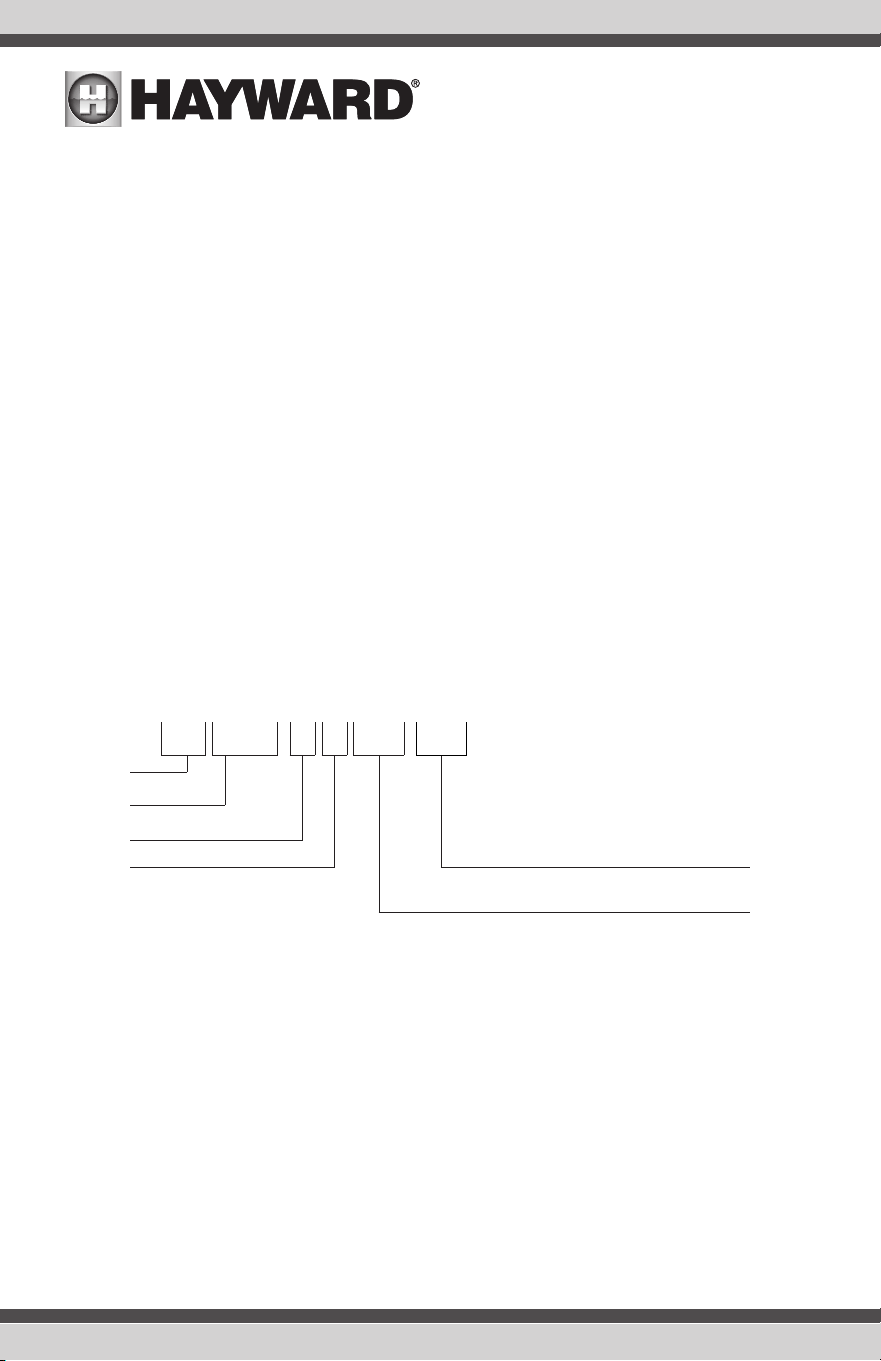
Identifying the Drive by Model Number
Each drive can be identified by its model number, as shown below.
HCP VFD
-
1 2 0021
-
1 P
Market
Product Type
Drive Size
Input 1 = 110 – 115
Voltage 2 = 200 – 240
4 = 380 – 480
No. Of Input Phases, 1P or 3P
Output Current x 10
3
USE ONLY HAYWARD GENUINE REPLACEMENT PARTSUSE ONLY HAYWARD GENUINE REPLACEMENT PARTS
Installation
Mounting Location
When preparing the mounting location, consider the following:
• The drive must be mounted in a vertical position only.
• Installation should be on a suitable flat, flame resistant surface, away from flammable material.
• Refer to Technical Data and ensure the chosen mounting location is within the drive specification.
• The mounting location should be free from vibration.
• Do not mount the drive in any area with excessive humidity, corrosive airborne chemicals or potentially
dangerous dust particles.
• Avoid mounting close to high heat sources.
• The drive must not be mounted in direct sunlight. If necessary, install a suitable shade cover.
• The mounting location must be free from frost.
• Do not restrict the flow of air through the drive heatsink. The drive generates heat which must be naturally
allowed to dissipate. Correct air clearance around the drive must be observed.
• If the location is subject to wide ambient temperature and air pressure variation, install a suitable pressure
compensation valve in the drive gland plate.
NOTE: If the drive has been in storage for a period longer than 2 years, the DC link capacitors must be reformed.
Refer to online documentation for further information.
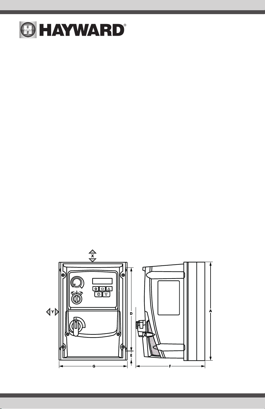
Specifications
Refer to the diagram below and the table on page 5 for dimensions of the VFD. Refer to your model number for
the Drive Size (page 3).
USE ONLY HAYWARD GENUINE REPLACEMENT PARTS
4
USE ONLY HAYWARD GENUINE REPLACEMENT PARTS
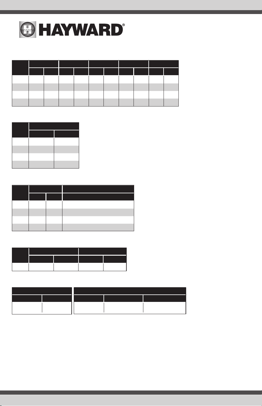
Dimensions
Drive
Size
A D E F G
mm in mm in mm in mm in mm in
1 232.0 9.13 189.0 7.44 25.0 0.98 162.0 6.37 161.0 6.34
2 257.0 10.12 200.0 7.87 28.5 1.12 182.0 7.16 188.0 7.40
3 310.0 12.20 251.5 9.90 33.4 1.31 238.0 9.37 211.0 8.30
4 360.0 14.17 300.0 11.08 226.0 8.89 275.0 10.82 240.0 9.44
Weight
Drive
Size
Weight
kg Ib
1 2.5 5.5
2 3.5 7.7
3 7.0 15.4
4 9.5 20.9
Carton
Mounting Clearance
Drive
Size
X Above & Below Y Either Side
mm in mm in
All 200 7.87 10 0.39
Mounting Bolts and Tightening Torque
Mounting Bolts Tightening Torques
Frame Size Frame Size
Control Terminals
Power Terminals
1 - 4 4 x M4 (#8) 1 - 3
4
0.5 Nm (4.4 lb-in)
0.5 Nm (4.4 lb-in)
1.5 Nm (13 lb-in)
4.1 Nm (36.5 lb-in)
Wiring
A fixed installation is required according to IEC61800-5-1 with a suitable disconnecting device installed between
the drive and the AC Power Source. The disconnecting device must conform to the local safety code / regulations
(e.g. within Europe, EN60204-1, Safety of machinery).
For compliance with CE and C Tick EMC requirements, refer to online documentation.
Drive
Size
Weight Size
kg Ib mm/in
1 4 9 345x205x205mm 13.5x8x8in
2 5.5 12 370x230x216mm 14.5x9x8.5in
3 9.1 20 460x305x270mm 18x12x10.5in
4 12.3 27 560x345x280mm 22x13.5x11in
5
USE ONLY HAYWARD GENUINE REPLACEMENT PARTSUSE ONLY HAYWARD GENUINE REPLACEMENT PARTS
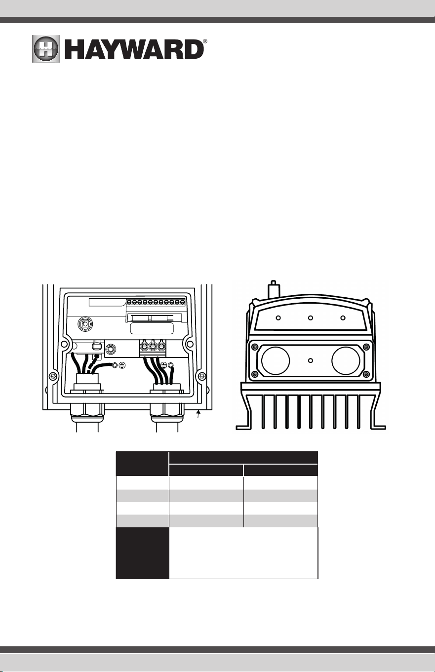
Gland Plate and Lock Off
The use of a suitable gland system is required to maintain the appropriate IP / NEMA rating. The gland plate has pre
moulded cable entry holes for power and motor connections suitable for use with glands as shown in the following
table. Where additional holes are required, these can be drilled to suitable size. Please take care when drilling to
avoid leaving any particles within the product.
UL rated ingress protection ("Type" ) is only met when cables are installed using a UL recognized bushing or
fitting for a flexible-conduit system which meets the required level of protection ("Type").
For conduit installations the conduit entry holes require standard opening to the required sizes specified per the
NEC.
Not intended for installation using rigid conduit system.
The power input cables should be dimensioned according to any local codes or regulations. Maximum
dimensions are given in the Rating Tables section of this manual.
• For 1 phase supply, the mains power cables should be connected to L1/L, L2/N.
• For 3 phase supplies, the mains power cables should be connected to L1, L2, and L3. Phase sequence is not
important.
Drive Size
Cable Gland Sizes
Power Cable Motor Cable
1 22mm M20 (PG22)
2 27mm M25 (PG21)
3 27mm M25 (PG21)
4 37mm PG29
NOTE
Typical drive heat losses are approximately
3% of operating load conditions. Above are
guidelines only and the operating ambient
temperature of the drive MUST be maintained
at all times.
NOTE: The motor cable length should not exceed 300 feet (100 meters). If longer cable lengths are necessary,
please contact Hayward for additional installation requirements.
L1/L
L3 EMC
Gland plate
can be removed
for installation
L2/N
UVW
1 2 3 4 5 6 7 8 9
10
11
I0I0I I0I0I
USE ONLY HAYWARD GENUINE REPLACEMENT PARTS
6
USE ONLY HAYWARD GENUINE REPLACEMENT PARTS
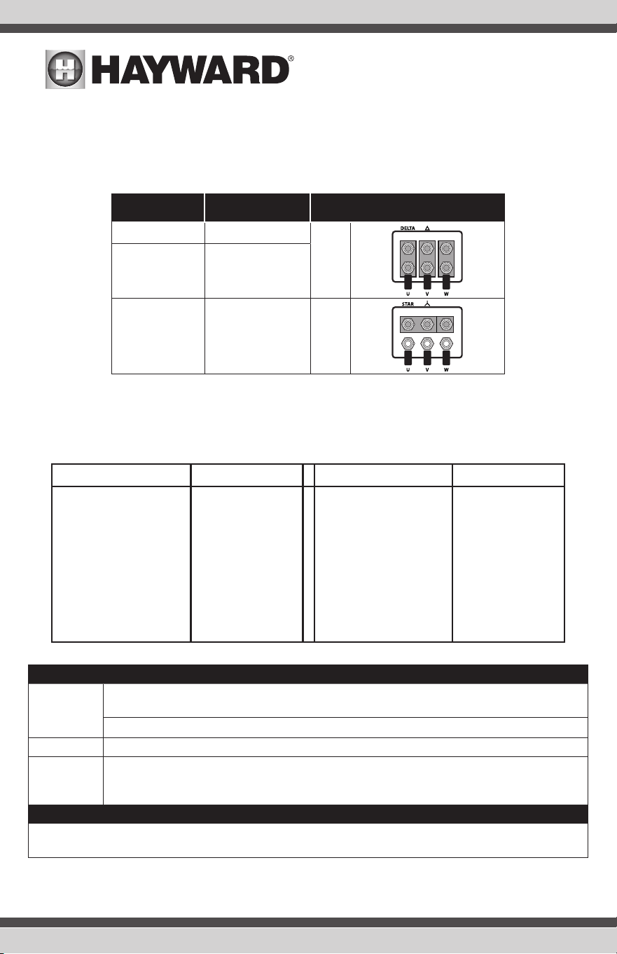
Motor Terminal Box Connections
Most general purpose motors are wound for operation on dual voltage supplies. This is indicated on the
nameplate of the motor. This operational voltage is normally selected when installing the motor by selecting either
STAR or DELTA connection. STAR always gives the higher of the two voltage ratings.
Incoming
Supply Voltage
Motor Nameplate
Voltages
Connection
230 230 / 460
Delta
460 460 / 690
460 230 / 460 Star
Information for UL Compliance
The drive is designed to meet the UL requirements. For an up to date list of UL compliant products, please refer
to UL listing NMMS.E226333. Reference numbers are on the drive label. In order to ensure full compliance, the
following must be fully observed.
Hayward Part Number UL Listing Hayward Part Number UL Listing
HCPVFD1400413P
HCPVFD2400583P
HCPVFD2400953P
HCPVFD3401403P
HCPVFD3401803P
HCPVFD3402403P
HCPVFD4403003P
HCPVFD4403903P
HCPVFD4404603P
HCPVFD2201053P
E3-140041-301C
E3-240058-304C
E3-240095-304C
E3-340140-304C
E3-340180-304C
E3-340240-304C
E3-440300-304C
E3-440390-304C
E3-440460-304C
E3-220105-304C
HCPVFD2201053P
HCPVFD3201803P
HCPVFD3202403P
HCPVFD4203003P
HCPVFD4204603P
HCPVFD2201051P
HCPVFD3201531P
E3-220105-304C
E3-320180-304C
E3-320240-304C
E3-420300-304C
E3-420460-304C
E3-220105-104C
E3-320153-104C
Input Power Supply Requirements
Supply
Voltage
200 – 240 RMS Volts for 230 Volt rated units, + /- 10% variation allowed. 240 Volt RMS
Maximum.
380 – 480 Volts for 400 Volt rated units, + / - 10% variation allowed, Maximum 500 Volts RMS.
Frequency 50 – 60Hz + / - 5% Variation
Short Circuit
Capacity
All drives are suitable for use on a circuit capable of delivering not more than 100kA maximum
short-circuit Amperes symmetrical with the specified maximum supply voltage when protected
by Class J fuses.
Mechanical Installation Requirements
All drive units are intended for installation within controlled environments which meet the condition limits
shown in the Environment section of this manual.
USE ONLY HAYWARD GENUINE REPLACEMENT PARTS
7
USE ONLY HAYWARD GENUINE REPLACEMENT PARTS
The drive can be operated within an ambient temperature range as stated in the Environment section of this
Quick Start Guide.
For IP66 (Nema 4X) units, installation in a pollution degree 2 environment is permissible.
Electrical Installation Requirements
Incoming power supply connection must be according to the Incoming Power Connection section of this Quick
Start Guide.
Suitable power and motor cables should be selected according to the data shown in Rating Tables section of
this Quick Start Guide and the National Electrical Code or other applicable local codes.
Motor Cable 75°C Copper must be used.
Power cable connections and tightening torques are shown in the Mechanical Dimensions section of this Quick
Start Guide.
Integral Solid Sate short circuit protection does not provide branch circuit protection. Branch circuit protection
must be provided in accordance with the national electrical code and any additional local codes. Ratings are
shown in the Rating Tables section of this Quick Start Guide.
For Canadian installations transient surge suppression must be installed on the line side of this equipment and
shall be rated 480Volt (phase to ground), 480 Volt (phase to phase), suitable for over voltage category iii and
shall provide protection for a rated impulse withstand voltage peak of 2.5kV.
UL Listed ring terminals / lugs must be used for all bus bar and grounding connections.
General Requirements
The drive provides motor overload protection, set at 150% of full load, in accordance with the National
Electrical Code (US).
Where a motor thermistor is fitted and connected to the drive, connection must be carried out according to the
information shown in the Motor Thermistor Connection section of the Quick Start Guide.
UL rated ingress protection (“Type” ) is only met when cables are installed using a UL recognized bushing or
fitting for a flexible conduit system which meets the required level of protection (“Type”).
For conduit installations the conduit entry holes require standard opening to the required sizes specified per
the NEC.
Not intended for installation using rigid conduit system.
WARNING: The opening of the branch-circuit protective device may be an indication that a fault has been
interrupted. To reduce the risk of fire or electric shock, current-carrying parts and other components of the
controller should be examined and replaced if damaged. If burnout of the current element of an overload relay
occurs, the complete overload relay must be replaced.
Control Terminal Wiring
• All analog signal cables should be suitably shielded. Twisted pair cables are recommended.
• Power and Control Signal cables should be routed separately where possible, and must not be routed parallel
to each other.
• Signal levels of different voltages e.g. 24 Volt DC and 110 Volt AC, should not be routed in the same cable.
• Maximum control terminal tightening torque is 0.5Nm.
• Control Cable entry conductor size: 0.05 – 2.5mm2 / 30 – 12 AWG.
USE ONLY HAYWARD GENUINE REPLACEMENT PARTS
8
USE ONLY HAYWARD GENUINE REPLACEMENT PARTS
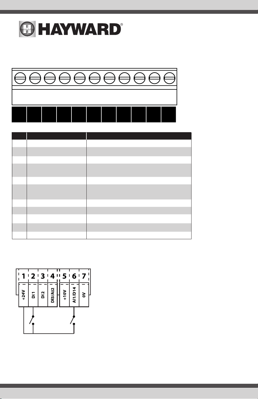
Control Terminal Connections
Non-Switched Units: Require external control signals to be connected to the control terminals.
+24
VDC
DI1 DI2 DI3
AI2
+10
VDC
DI4
AI1
0V A0 0V RL1 RL2
No. Purpose Function
1 +24VDC 100mA Output 24 VDC Output
2 DI1 Digital Input 1 Close to terminal 1 to enable Keypad
3 DI2 Digital Input 2 Not Used
4 DI3 Digital Input 3/
AI2 Analog Input 2
Not Used
5 +10VDC 5mA Output 10 VDC Output for external potentiometer
6 DI4 Digital Input 4/
AI1 Analog Input 1
Open: Keypad Setting
Close: Full Speed
7 0VDC Common Terminal 1
8 AO Analog Output Not Used
9 0VDC Common
10 RL1 Output Relay Not Used
11 RL2 Output Relay Not Used
Connection Example
1 2 3 4 5 6 7 8 9
10
11
USE ONLY HAYWARD GENUINE REPLACEMENT PARTS
9
USE ONLY HAYWARD GENUINE REPLACEMENT PARTS
Control Terminal Connections
Non-Switched Units: Require external control signals to be connected to the control terminals.
+24
VDC
DI1 DI2 DI3
AI2
+10
VDC
DI4
AI1
0V A0 0V RL1 RL2
No. Purpose Function
1 +24VDC 100mA Output 24 VDC Output
2 DI1 Digital Input 1 Close to terminal 1 to enable Keypad
3 DI2 Digital Input 2 Not Used
4 DI3 Digital Input 3/
AI2 Analog Input 2
Not Used
5 +10VDC 5mA Output 10 VDC Output for external potentiometer
6 DI4 Digital Input 4/
AI1 Analog Input 1
Open: Keypad Setting
Close: Full Speed
7 0VDC Common Terminal 1
8 AO Analog Output Not Used
9 0VDC Common
10 RL1 Output Relay Not Used
11 RL2 Output Relay Not Used
Connection Example
Factory Default Functions
No.
Description
DI1 0/1 Open : Stop/Disable
Closed : Enable Keypad
DI4
Maximum Speed (Default 60.0 Hz)
Operation
Before starting the VFD, ensure that all connections have been made properly and are secure.
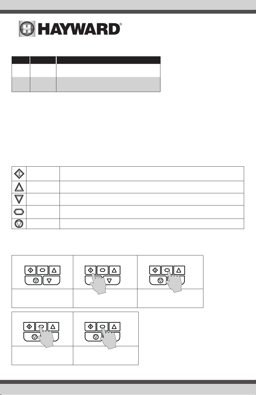
Keypad and Display
The drive is configured and its operation monitored via the keypad and display. Refer to the table below for basic
operation.
START
When in keypad mode, used to start a stopped drive or to reverse the direction of rotation if bi-
directional keypad mode is enabled.
UP
Used to increase speed in real-time mode or to increase parameter values in parameter edit
mode.
DOWN
Used to decrease speed in real-time mode or to decrease parameter values in parameter edit
mode.
NAVIGATE
Used to display real-time information, to access and exit parameter edit mode and to store
parameter changes.
RESET /STOP Used to reset a tripped drive.
Operating Displays
STOP H 50
0 A 2
3
Drive Stopped / Disabled Start. Drive is enabled / running,
display shows the output
frequency (Hz)
Press the Navigate key for < 1
second. The display will show the
motor current (Amps)
P 1
50 1500
Press the Navigate key for < 1
second. The display will show
the motor power (kW)
If P-10 > 0, pressing the
Navigate
key for < 1 second will
display the
motor speed (RPM)
.
USE ONLY HAYWARD GENUINE REPLACEMENT PARTS
10
USE ONLY HAYWARD GENUINE REPLACEMENT PARTS
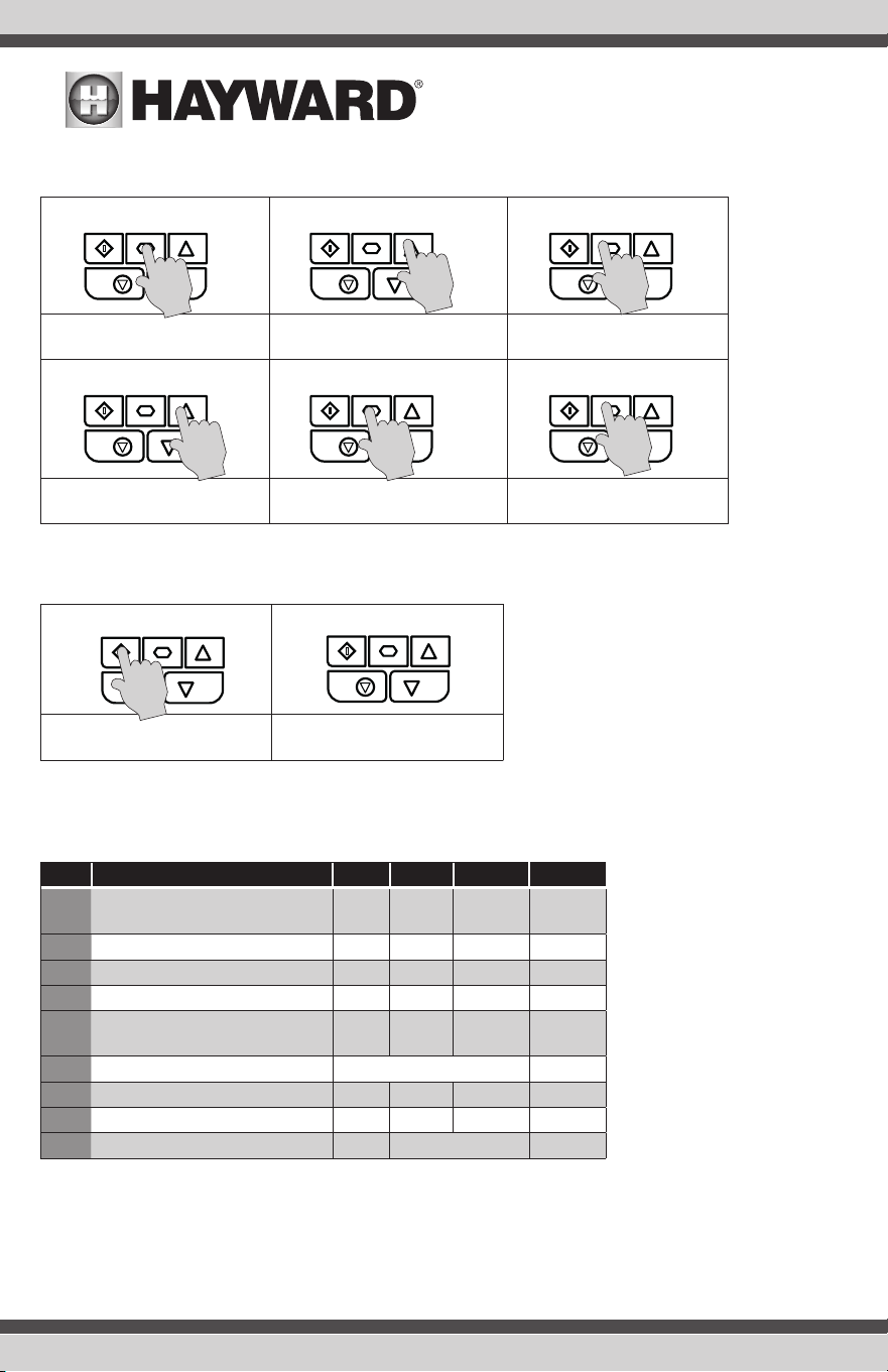
Changing Parameters
STOP P -01 P-08
Press and hold the Navigate key
> 2 seconds
Use the up and down keys to
select the required parameter
Press the Navigate key for < 1
second
10 P-08 P-08
Adjust the value using the Up and
Down keys
Press for < 1 second to return to
the parameter menu
Press for > 2 seconds to return
to the operating display
Resetting a Fault
0-1 Stop
Press the Stop key. The display
will show “SToP”
Available Parameters
The parameters avaible are shown in the table below.
Par. Description Min
Max
Default Units
P-01
Maximum Frequency/Speed Limit
P-02 500.0
50.0
(60.0)
Hz/RPM
P-02
Minimum Frequency/Speed Limit
0.0 P-01 36.0 Hz/RPM
P-03 Acceleration Ramp Time 0.00 600.0 5.0 s
P-04 Deceleration Ramp Time 0.00 600.0 5.0 s
P-07
Motor Rated Voltage/Back
EMF at
rated speed (PM/BLDC)
0
250/
500
230/460 V
P-08 Motor Rated Current
Drive Rating Dependent
A
P-09 Motor Rated Frequency 10 500 60 Hz
P-10 Motor Rated Speed 0 30000 0 RPM
P-11
Low Frequency Torque Boost
0.0
Drive Dependent
%
USE ONLY HAYWARD GENUINE REPLACEMENT PARTS
11
USE ONLY HAYWARD GENUINE REPLACEMENT PARTS
Technical Data
Operational ambient temperature range
Enclosed Drives: -20 ... 40°C (frost and condensation free)
Storage ambient temperature range: -40 … 60°C
Maximum altitude: 2000m. Derate above 1000m: 1% / 100m
Maximum humidity: 95%, non-condensing
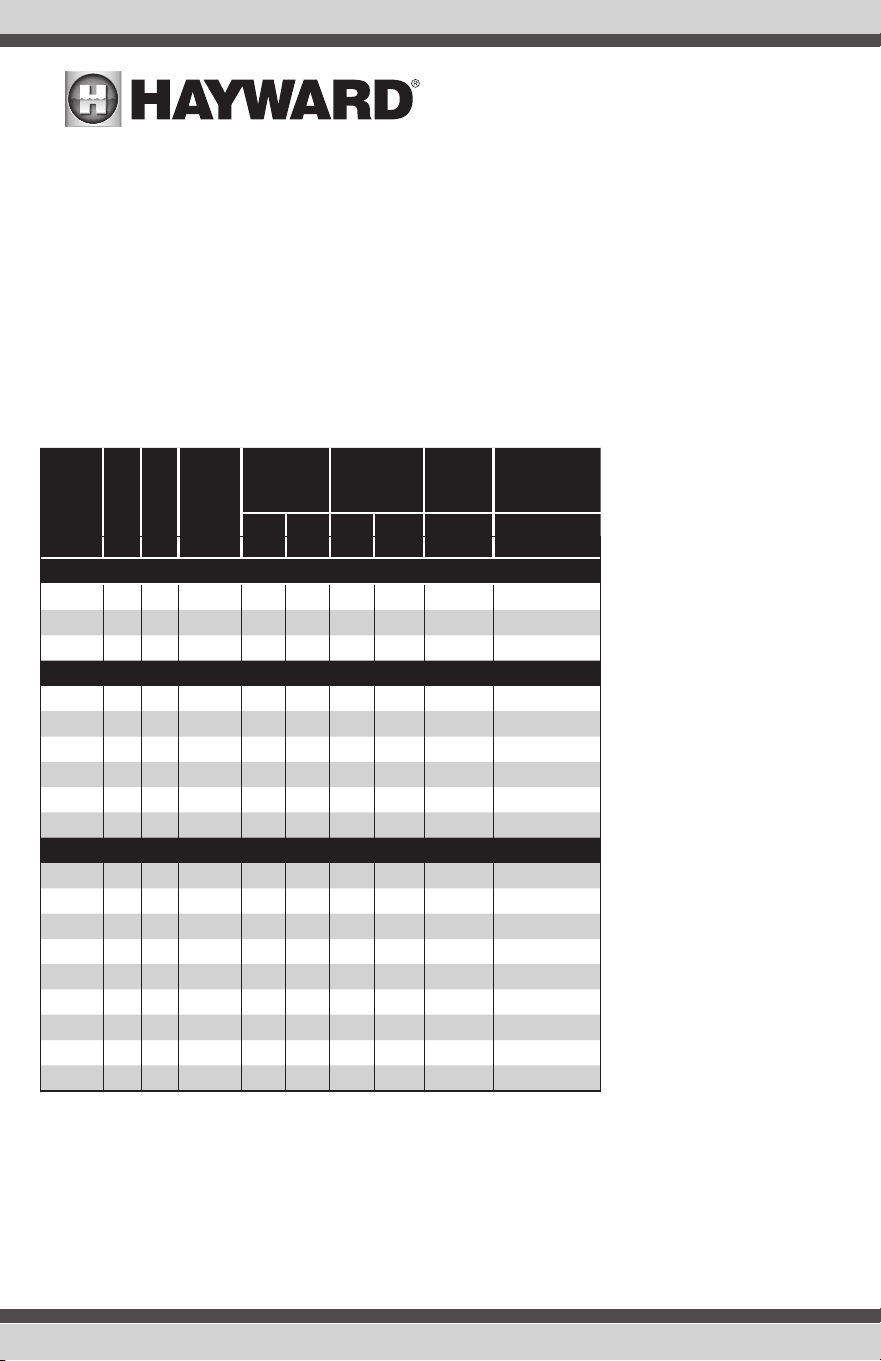
Ratings Table
Frame
Size
kW HP
Input
Current
Fuse/MCB
(Type B)
Maximum
Cable Size
Output
Current
Recommended
Brake
Resistance
Non
UL
UL mm
AWG
A Ω
110 - 115 (+ / - 10%) V 1 Phase Input, 230V 3 Phase Output (Voltage Doubler)
1 0.37 0.5 7.8 10 10 8 8 2.3 -
1 0.75 1 15.8 25 20 8 8 4.3 -
2 1.1 1.5 21.9 32 30 8 8 5.8 100
200 - 240 (+ / - 10%) V 1 Phase Input, 3 Phase Output
1 0.37 0.5 3.7 10 6 8 8 2.3 -
1 0.75 1 7.5 10 10 8 8 4.3 -
1 1.5 2 12.9 16 17.5 8 8 7 -
2 1.5 2 12.9 16 17.5 8 8 7 100
2 2.2 3 19.2 25 25 8 8 10.5 50
3 4 5 29.2 40 40 8 8 15.3 25
200 - 240 (+ / - 10%) V 3 Phase Input, 3 Phase Output
1 0.37 0.5 3.4 6 6 8 8 2.3 -
1 0.75 1 5.6 10 10 8 8 4.3 -
1 1.5 2 8.9 16 15 8 8 7 -
2 1.5 2 8.9 16 15 8 8 7 100
2 2.2 3 12.1 16 17.5 8 8 10.5 50
3 4 5 20.9 32 30 8 8 18 25
3 5.5 7.5 26.4 40 35 8 8 24 20
4 7.5 10 33.3 40 45 16 5 30 15
4 11 15 50.1 63 70 16 5 46 10
USE ONLY HAYWARD GENUINE REPLACEMENT PARTS
12
USE ONLY HAYWARD GENUINE REPLACEMENT PARTS
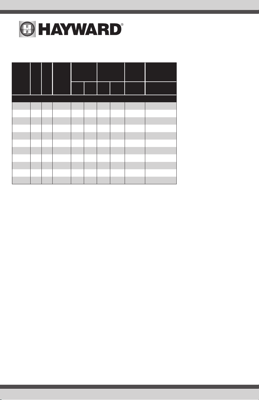
Ratings Table (continued)
Frame
Size
kW HP
Input
Current
Fuse/MCB
(Type B)
Maximum
Cable Size
Output
Current
Recommended
Brake
Resistance
Non
UL
UL mm
AWG
A Ω
380 - 480 (+ / - 10%)V 3 Phase Input, 3 Phase Output
1 0.75 1 3.5 6 6 8 8 2.2 -
1 1.5 2 5.6 10 10 8 8 4.1 -
2 1.5 2 5.6 10 10 8 8 4.1 250
2 2.2 3 7.5 16 10 8 8 5.8 200
2 4 5 11.5 16 15 8 8 9.5 120
3 5.5 7.5 17.2 25 25 8 8 14 100
3 7.5 10 21.2 32 30 8 8 18 80
3 11 15 27.5 40 35 8 8 24 50
4 15 20 34.2 40 45 16 5 30 30
4 18.5 25 44.1 50 60 16 5 39 22
4 22 30 51.9 63 70 16 5 46 22
NOTE Cable sizes shown are the maximum possible that may be connected to the drive. Cables should be
selected according to local wiring codes or regulations at the point of installation.
USE ONLY HAYWARD GENUINE REPLACEMENT PARTS
13
USE ONLY HAYWARD GENUINE REPLACEMENT PARTS
Troubleshooting
Fault Code Messages
Fault Code
No.
Description
0I-b
01 Brake channel over current
OL-br 02 Brake resistor overload
0-I 03 Output Over Current
I_t-trP 04
Motor Thermal Overload (I2t)
0-volt 06 Over voltage on DC bus
U-volt 07 Under voltage on DC bus
0-t 08 Heatsink over temperature
U-t 09 Under temperature
U-deF 10 Reset drive to defaults
E-trip 11 External trip
FLt-dc 13 DC bus ripple too high
P-LOSS 14 Input phase loss trip
h0-I 15 Output Over Current
th-Flt 16
Faulty thermistor on heatsink
dAtA-F 17
Internal memory fault (IO)
4-20 F 18 4-20mA Signal Lost
dAtA-E 19
Internal memory fault (DSP)
F-Ptc 21 Motor PTC thermistor trip
FAn-F 22
Cooling Fan Fault (IP66 only)
O-heat 23
Drive internal temperature too high
OUt-F 26 Output Fault
NOTE: Following an over current or overload trip (3, 4, 5, 15), the drive may not be reset until the reset time delay
has elapsed to prevent damage to the drive.
USE ONLY HAYWARD GENUINE REPLACEMENT PARTS
14
USE ONLY HAYWARD GENUINE REPLACEMENT PARTS

For further information or consumer
technical support, visit our website at
www.hayward.com
Hayward is a registered trademark
of Hayward Industries, Inc. © 2020 Hayward Industries, Inc.
All other trademarks not owned by Hayward are the property of their respective owners.
Hayward is not in any way affiliated with or endorsed by those third parties.
USE ONLY HAYWARD GENUINE REPLACEMENT PARTSUSE ONLY HAYWARD GENUINE REPLACEMENT PARTS