CMT912AUSTRAL
CMT9AUSTRALINT
CMT12AUSTRALINT
CMT14AUSTRALEXT
30
32
33
26
21
20
13
12
1
2
3
4
1
2
3
1
2
3
5
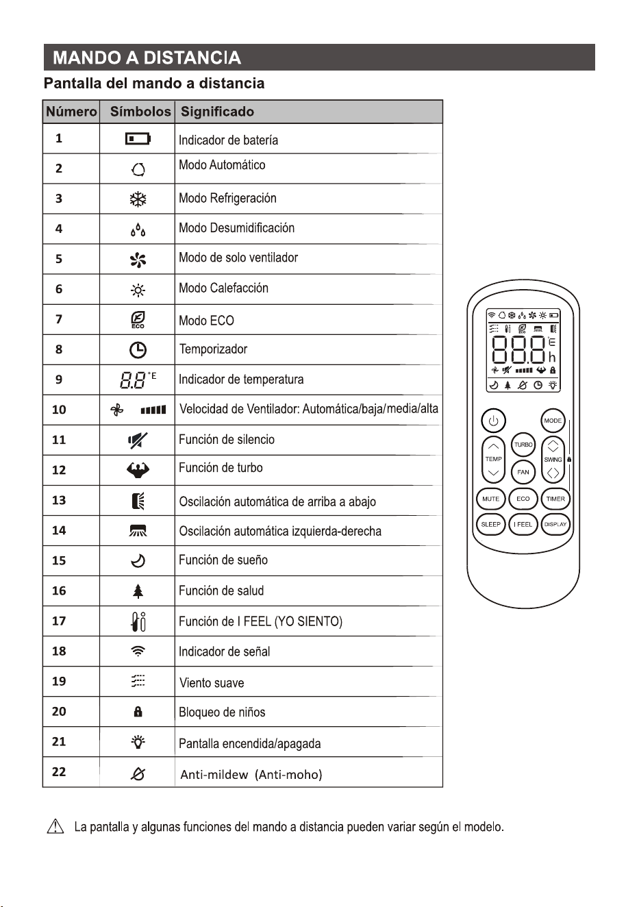
6
7
8
9
10
11
-20 ~30
0 ~30
-15 ~53
12
13
14
15
16
17
6
18
19
R32
15m
10m
15g/m
5m
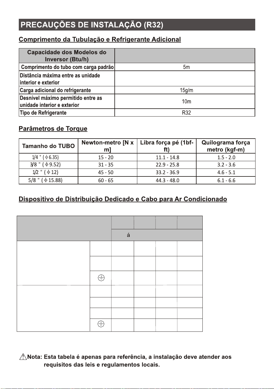
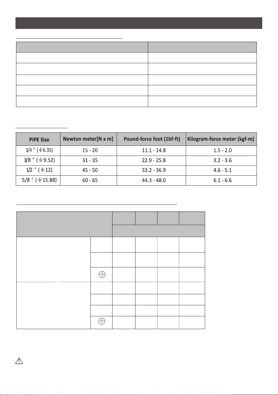
1/4(6.35)
3/8 ( 9.52)
1/2(12)
5/8(15.88)
2
2.5mm
Tipo inversor
modelo capacidad (Btu/h)
2
2.5mm
2
2.5mm
2
2.5mm
2
2.5mm
2
2.5mm
2
0.75mm
2
0.75mm
2
0.75mm
2
0.75mm
2
0.75mm
2
0.75mm
2
0.75mm
2
0.75mm
9k
12k
18k
27k
(en la unidad exterior)
)
N
L
1
N
L
rea de la zona
9K/12K
(para cada unidad interior)
20
21
2.8 (70mm)
22
23
24
25
26
LA
1A
NA
LB
1B
NB
L
1
N
N
L
1
N
N
N
L
LA
1A
NA
LB
1B
NB
LC
1C
NC
L
1
N
N
L
1
N
N
L
1
N
N
N
L
Para sistema dual
Para sistema triple
Exterior
Interior B
Interior A
Fuente de alimentaci n
Fuente de alimentaci n
Interior C
Interior B
Interior A
Exterior
27
28
29
30
31
<40
<40
32
33
34

CMT912AUSTRAL
CMT9AUSTRALINT
CMT12AUSTRALINT
CMT14AUSTRALEXT
30
32
33
26
21
20
13
12

1
2
3
4
5
6
7
8
9

10
11
-15 a 53
-20 a 30
12
13
14
15
16
17
6
18
19
2
2.5mm
TIPO INVERSOR
modelo capacidade (Btu/h)
2
2.5mm
2
2.5mm
2
2.5mm
2
2.5mm
2
2.5mm
2
0.75mm
2
0.75mm
2
0.75mm
2
0.75mm
2
0.75mm
2
0.75mm
2
0.75mm
2
0.75mm
9k
12k
18k
27k
N
L
1
N
L
rea seccional
Cabo de alimentação
(Na unidade externa)
Cabo de conexão
15m
9K/12K
(Para cada unidade interna)
20
21
22
23
24
25
26
LA
1A
NA
LB
1B
NB
L
1
N
N
L
1
N
N
N
L
LA
1A
NA
LB
1B
NB
LC
1C
NC
L
1
N
N
L
1
N
N
L
1
N
N
N
L
Para sistema duplo
l
Para sistema triplo
Exterior
Interior B
Interior A
Fonte de energia
Interior C
Interior B
Interior A
Exterior
Fonte de energia
27
28
29
30
31
32
33
34
CMT912AUSTRAL
CMT9AUSTRALINT
CMT12AUSTRALINT
CMT14AUSTRALEXT

CONTENTS
* The design and specifications are subject to change without prior notice for product improvement.
Consult with the sales agency or manufacturer for details.
* The shape and position of buttons and indicators may vary according to the model, but their function
are the same.
SAFETY PRECAUTIONS
NAME OF PARTS
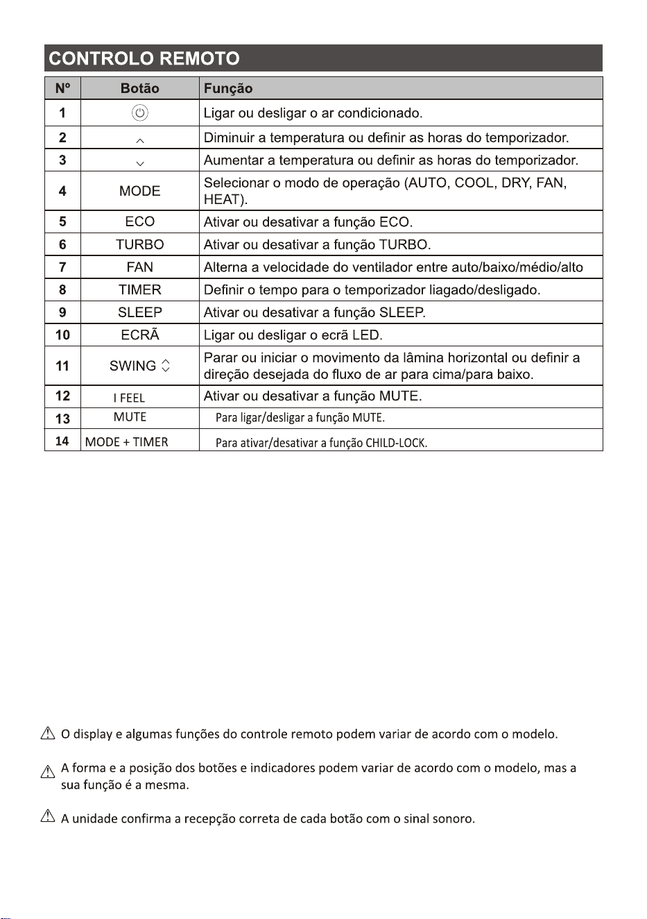
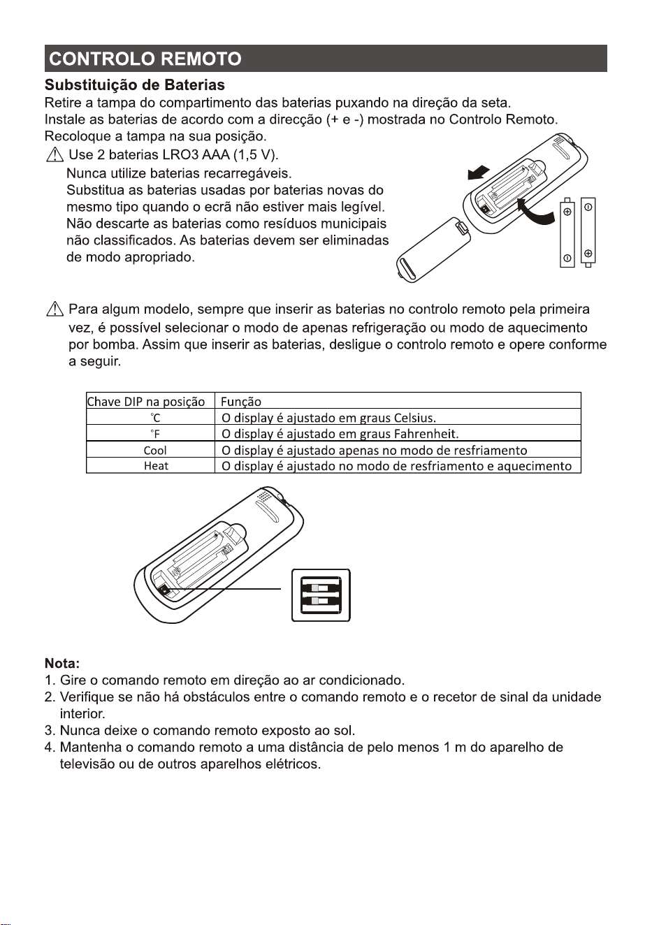
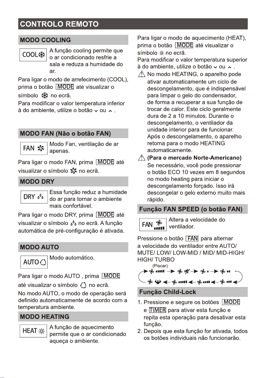
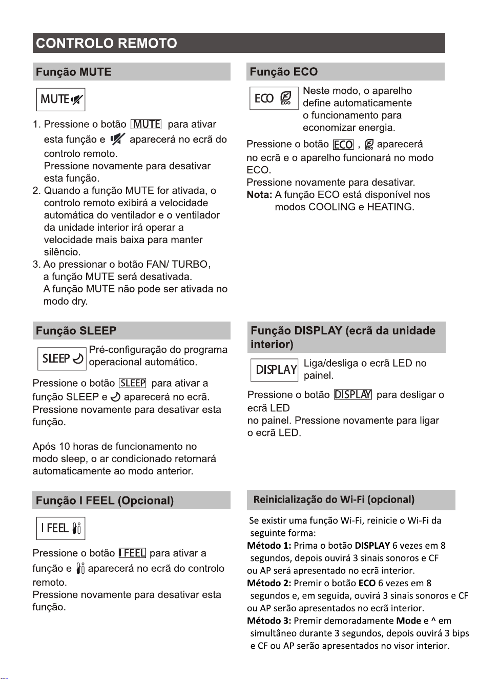
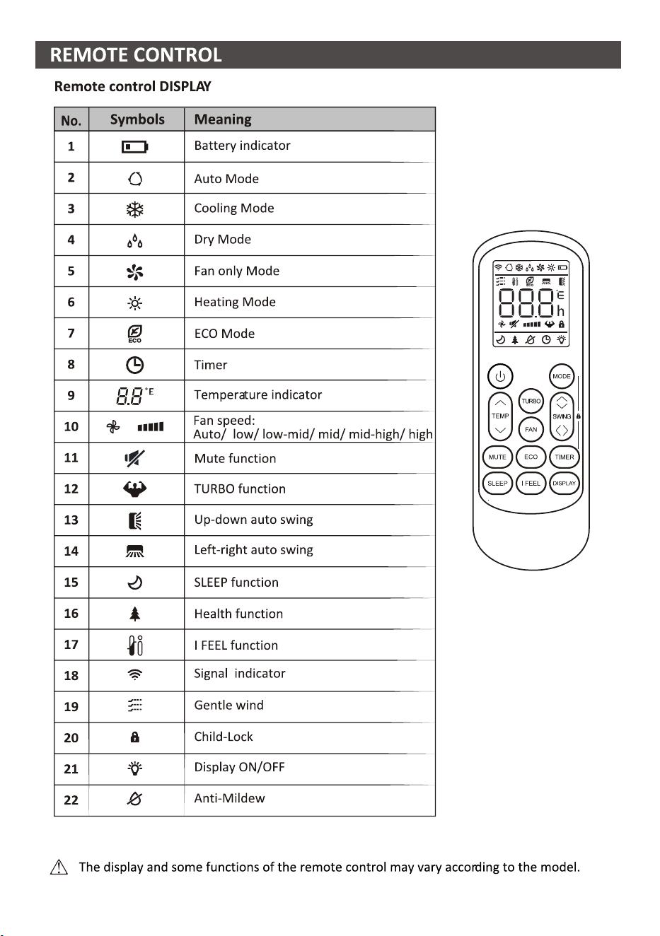
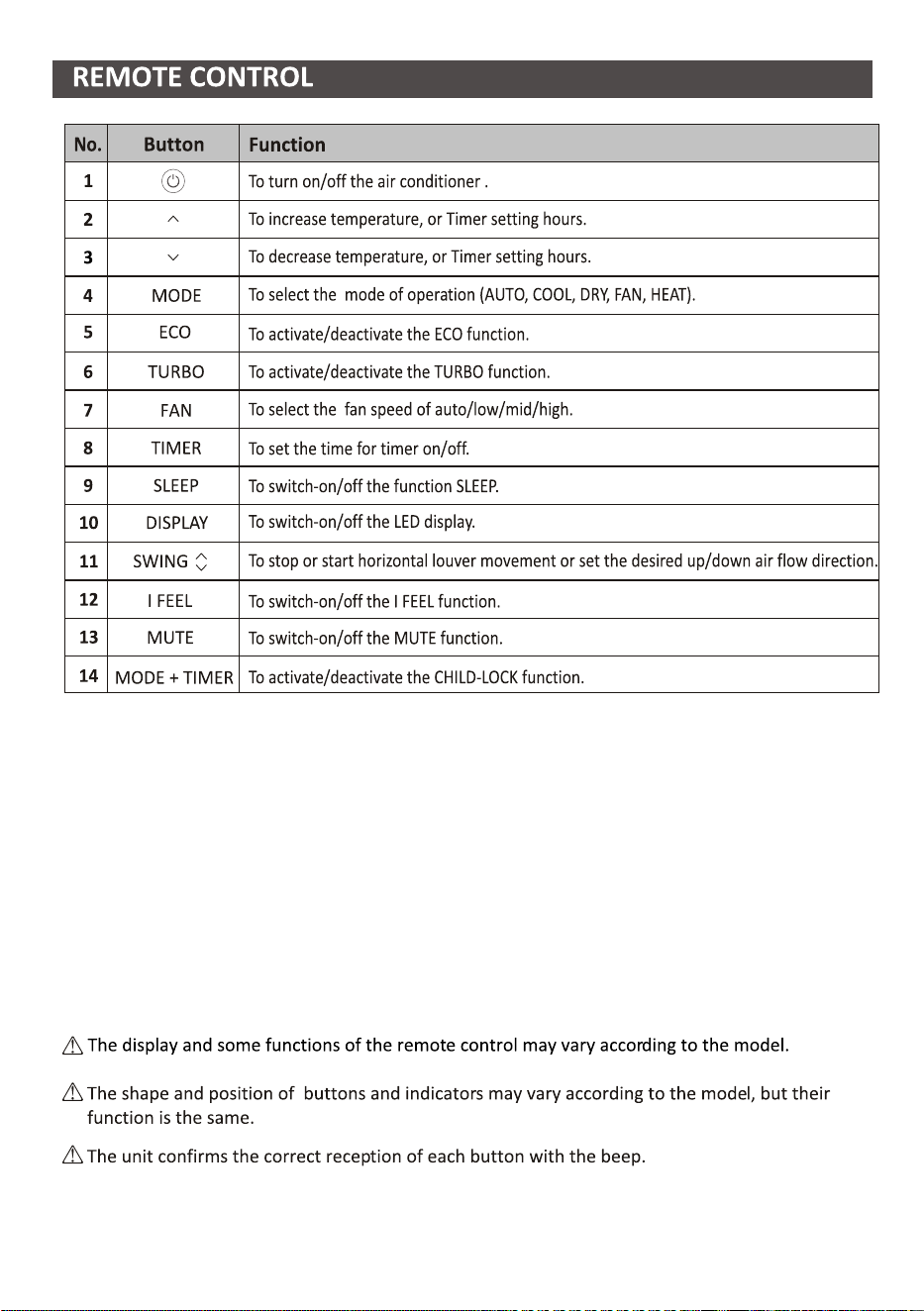
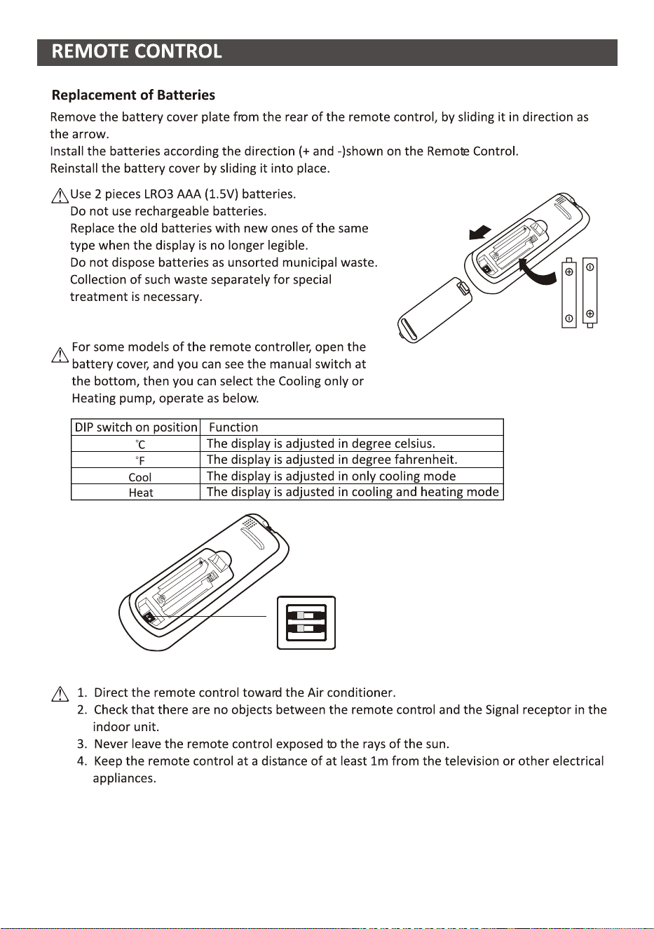
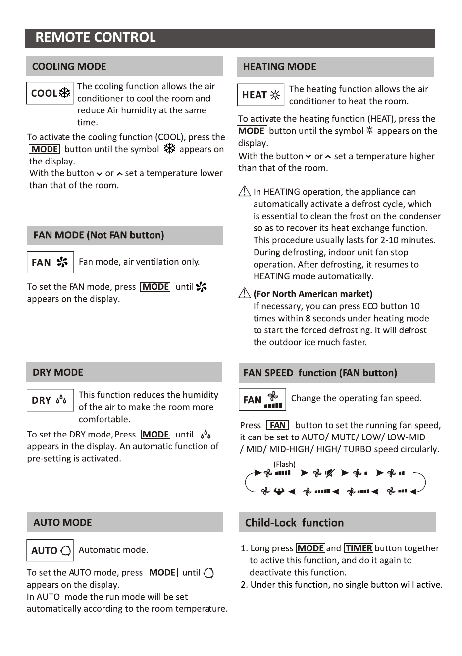
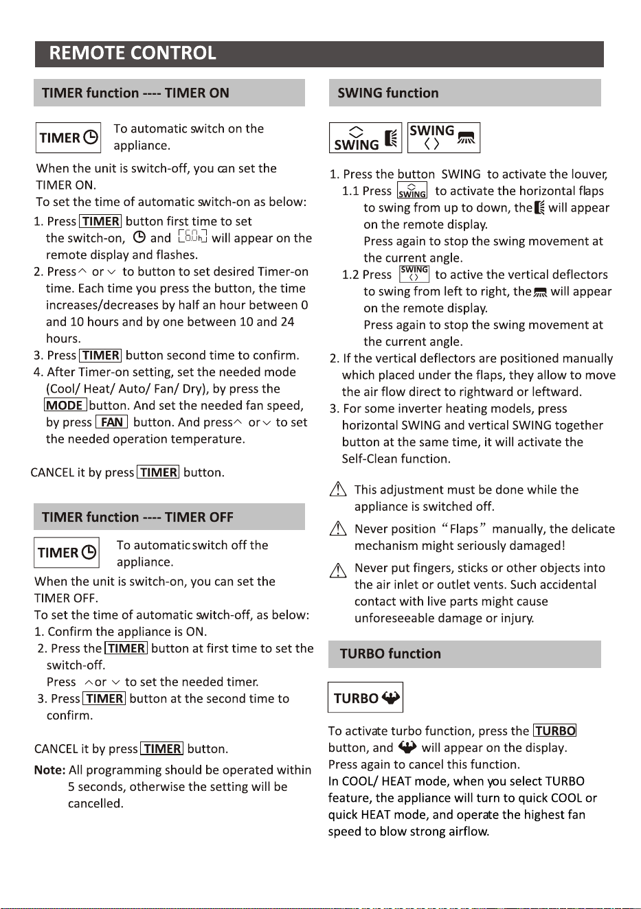
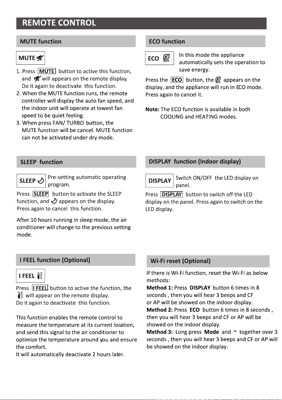
REMOTE CONTROL
OPERATION INSTRUCTIONS
INSTALLATION PRECAUTIONS
INDOOR UNIT INSTALLATION
OUTDOOR UNIT INSTALLATION
TEST OPERATION
MAINTENANCE
TROUBLESHOOTING
INSTRUCTION FOR SERVICING(R32)
...........................................................................................................................30
......................................................................................................26
........................................................................................................21
...............................................................................................................................4
............................................................................................................... .....1
..................................................................................................... ...18
................................................................................................................................32
................................................................................................13
......................................................................................................................33
............................................................................................................12
...........................................................................................................................6

1. Read this guide before installing and using the appliance.
2. During the installation of the indoor and outdoor units the access to the working area should be
forbidden to children. Unforeseeable accidents could happen.
3. Make sure that the base of the outdoor unit is firmly fixed.
4. Check that air cannot enter the refrigerant system and check for refrigerant leaks when moving
the air conditioner.
5. Carry out a test cycle after installing the air conditioner and record the operating data.
6. Protect the indoor unit with a fuse of suitable capacity for the maximum input current or with
another overload protection device.
7. Ensure that the mains voltage corresponds to that stamped on the rating plate. Keep the switch
or power plug clean. Insert the power plug correctly and firmly into the socket, thereby avoiding
the risk of electric shock or fire due to insufficient contact.
8. Check that the socket is suitable for the plug , otherwise have the socket changed.
9. The appliance must be fitted with means for disconnection from the supply mains having a
contact separation in all poles that provide full disconnection under over voltage category III
conditions, and these means must be incorporated in the fixed wiring in accordance with the
wiring rules.
10. The air conditioner must be installed by professional or qualified persons.
11. Do not install the appliance at a distance of less than 50 cm from inflammable substances
(alcohol, etc.) Or from pressurized containers (e.g. spray cans).
12. If the appliance is used in areas without the possibility of ventilation, precautions must be taken
to prevent any leaks of refrigerant gas from remaining in the environment and creating a danger
of fire.
13. The packaging materials are recyclable and should be disposed of in the separate waste bins.
Take the air conditioner at the end of its useful life to a special waste collection center for disposal.
14. Only use the air conditioner as instructed in this booklet. These instructions are not intended to
cover every possible condition and situation. As with any electrical household appliance, common
sense and caution are therefore always recommended for installation, operation and maintenance.
15. The appliance must be installed in accordance with applicable national regulations.
16. Before accessing the terminals, all the power circuits must be disconnected from the power supply.
17. The appliance shall be installed in accordance with national wiring regulations.
18. This appliance can be used by children aged from 8 years and above and persons with reduced
physical, sensory or mental capabilities or lack of experience and knowledge if they have been
given supervision or instruction concerning use of the appliance in a safe way and understand
the hazards involved. Children shall not play with the appliance. Cleaning and user maintenance
shall not be made by children without supervision.
SAFETY RULES AND RECOMMENDATIONS FOR THE INSTALLER
SAFETY PRECAUTIONS
1

19. Do not try to install the conditioner alone, always contact specialized technical personnel.
20. Cleaning and maintenance must be carried out by specialized technical personnel. In any case
disconnect the appliance from the mains electricity supply before carrying out any cleaning or
maintenance.
21. Ensure that the mains voltage corresponds to that stamped on the rating plate. Keep the switch
or power plug clean. Insert the power plug correctly and firmly into the socket, thereby avoiding
the risk of electric shock or fire due to insufficient contact.
22. Do not pull out the plug to switch off the appliance when it is in operation, since this could create
a spark and cause a fire, etc.
23. This appliance has been made for air conditioning domestic environments and must not be used
for any other purpose, such as for drying clothes, cooling food, etc.
24. Always use the appliance with the air filter mounted. The use of the conditioner without air filter
could cause an excessive accumulation of dust or waste on the inner parts of the device with
possible subsequent failures.
25. The user is responsible for having the appliance installed by a qualified technician, who must
check that it is earth in accordance with current legislation and insert a thermos magnetic circuit
breaker.
26. The batteries in remote controller must be recycled or disposed of properly. Disposal of Scrap
Batteries --- Please discard the batteries as sorted municipal waste at the accessible collection point.
27. Never remain directly exposed to the flow of cold air for a long time. The direct and prolonged
exposition to cold air could be dangerous for your health. Particular care should be taken in the
rooms where there are children, old or sick people.
28. If the appliance gives off smoke or there is a smell of burning, immediately cut off the power
supply and contact the Service Center.
29. The prolonged use of the device in such conditions could cause fire or electrocution.
30. Have repairs carried out only by an authorised Service Centra of the manufacturer. Incorrect
repair could expose the user to the risk of electric shock, etc.
31. Unhook the automatic switch if you foresee not to use the device for a long time. The airflow
direction must be properly adjusted.
32. The flaps must be directed downwards in the heating mode and upwards in the cooling mode.
33. Ensure that the appliance is disconnected from the power supply when it will remain inoperative
for a long period and before carrying out any cleaning or maintenance.
34. Selecting the most suitable temperature can prevent damage to the appliance.
SAFETY RULES AND RECOMMENDATIONS FOR THE INSTALLER
SAFETY PRECAUTIONS
2

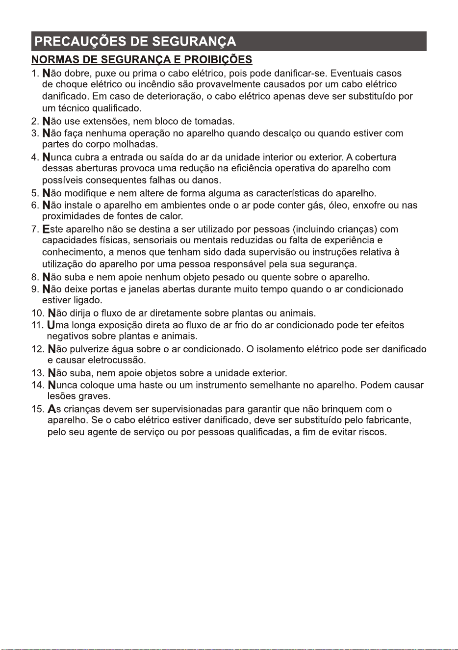
1. Do not bend, tug or compress the power cord since this could damage it. Electrical shocks or fire
are probably due to a damaged power cord. Specialized technical personnel only must replace a
damaged power cord.
2. Do not use extensions or gang modules.
3. Do not touch the appliance when barefoot or parts of the body are wet or damp.
4. Do not obstruct the air inlet or outlet of the indoor or the outdoor unit. The obstruction of these
openings causes a reduction in the operative efficiency of the conditioner with possible consequent
failures or damages.
5. In no way alter the characteristics of the appliance.
6. Do not install the appliance in environments where the air could contain gas, oil or sulphur or near
sources of heat.
7. This appliance is not intended for use by persons (including children ) with reduced physical,
sensory or mental capabilities, or lack of experience and knowledge, unless they have been given
supervision or instruction concerning use of the appliance by a person responsible for their safety.
8. Do not climb onto or place any heavy or hot objects on top of the appliance.
9. Do not leave windows or doors open for long when the air conditioner is operating.
10. Do not direct the airflow onto plants or animals.
11. A long direct exposition to the flow of cold air of the conditioner could have negative effects on
plants and animals.
12. Do not put the conditioner in contact with water. The electrical insulation could be damaged and
thus causing electrocution.
13. Do not climb onto or place any objects on the outdoor unit.
14. Never insert a stick or similar object into the appliance. It could cause injury.
15. Children should be supervised to ensure that they do not play with the appliance. If the supply
cord is damaged, it must be replaced by the manufacturer, its service agent or similarly qualified
persons in order to avoid a hazard.
SAFETY RULES AND PROHIBITIONS
SAFETY PRECAUTIONS
3
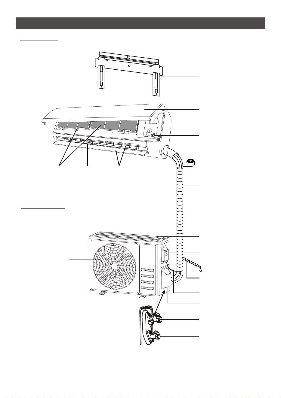
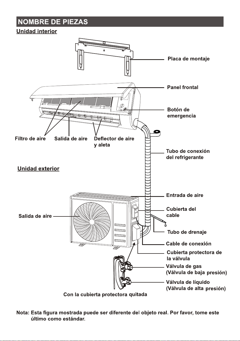
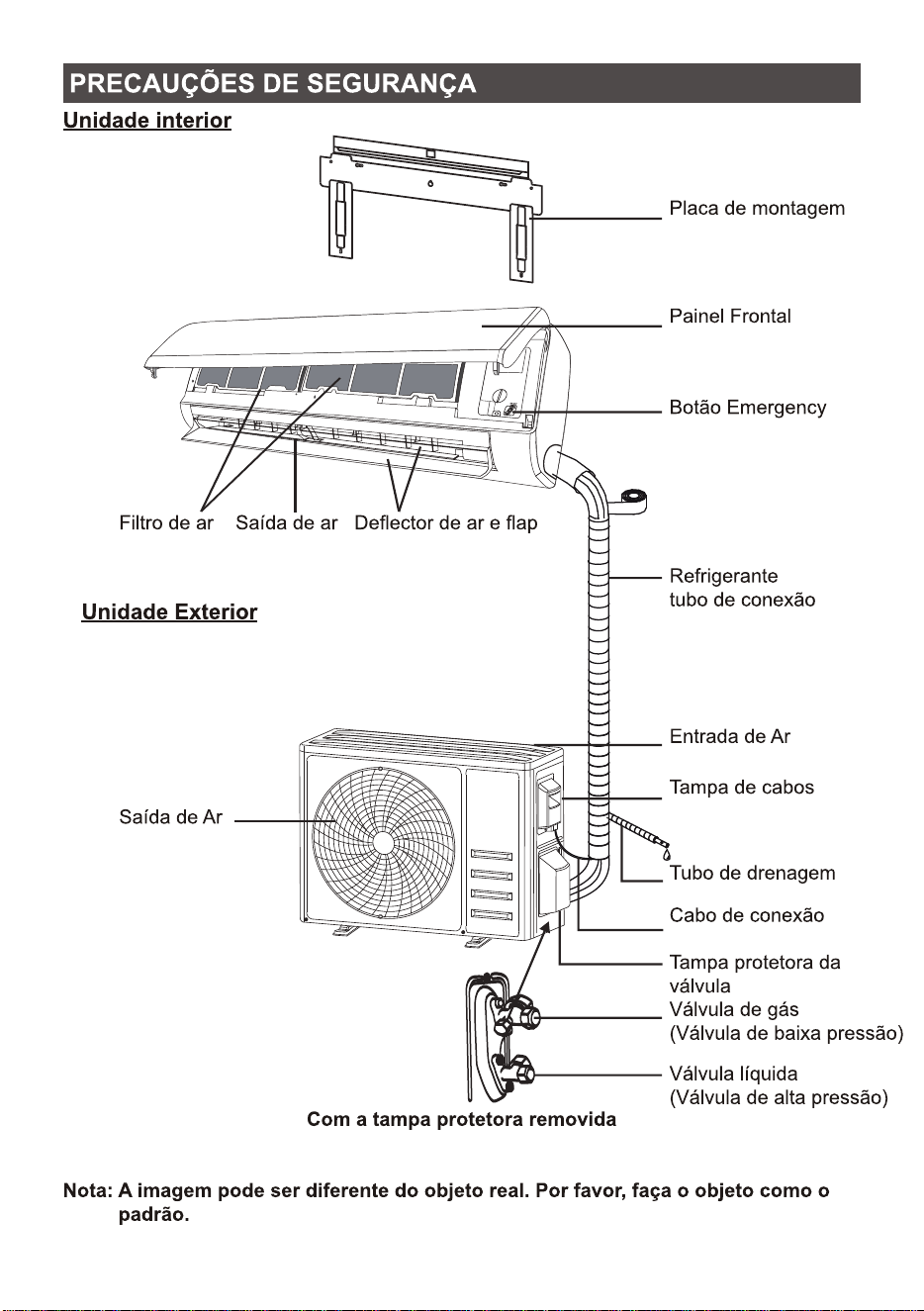
NAME OF PARTS
Emergency button
Front panel
Indoor Unit
Outdoor Unit
Note: This figure shown may be different from the actual object. Please take the latter as the
standard.
Mounting plate
Air inlet
Drainage pipe
Wiring cover
Connection wiring
Valve protective cover
With the protective cover removed
Liquid valve
(High pressure valve)
Gas valve
(Low pressure valve)
Refrigerant
connecting pipe
Air deflector and flap
Air outlet
Air outlet
Air filter
4
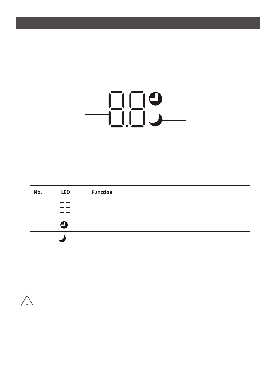
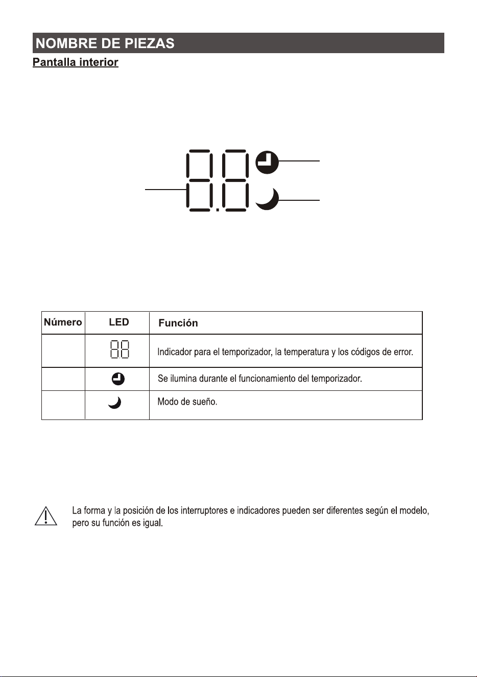
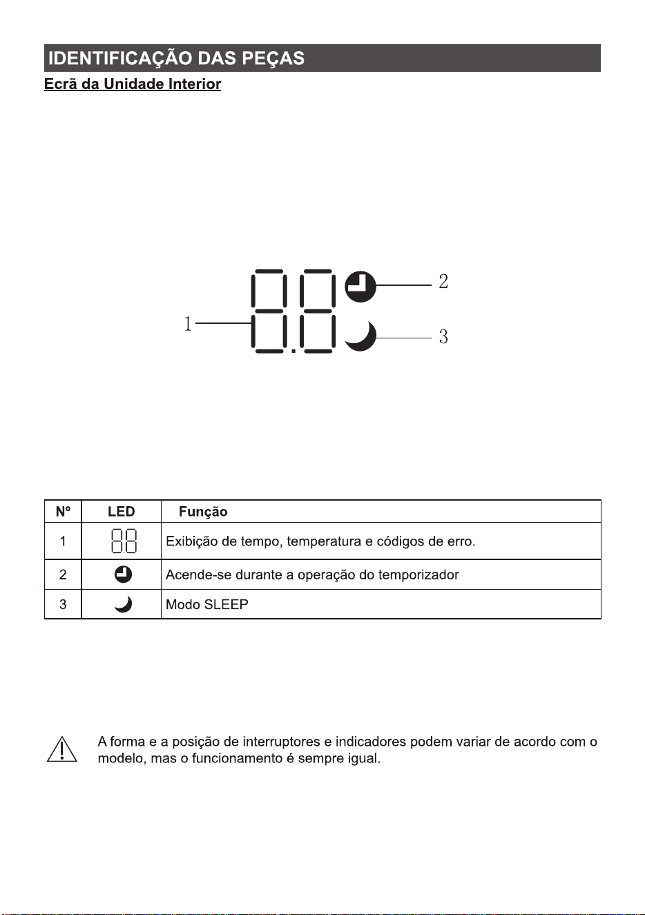
Indoor Display
The shape and position of switches and indicators may be different according to the model,
but their function is the same.
1
2
3
NAME OF PARTS
1
2
3
Indicator for Timer, temperature and Error codes.
Lights up during Timer operation.
SLEEP mode
5
6
7
8
9
10
11
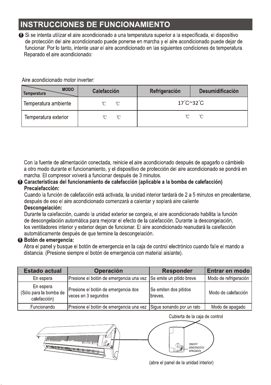
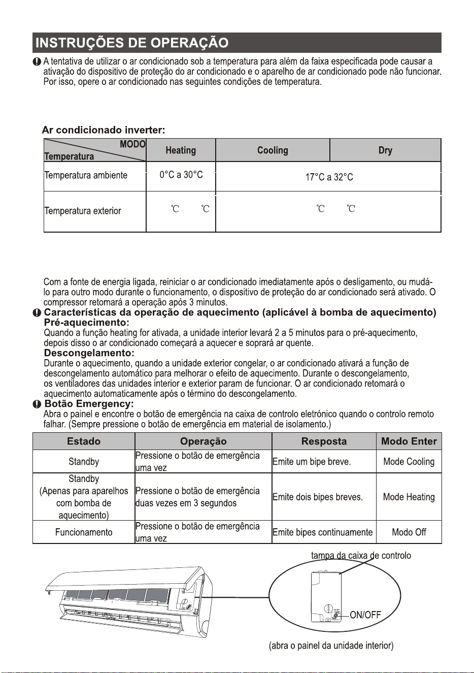
(open the panel of indoor unit)
control-box cover
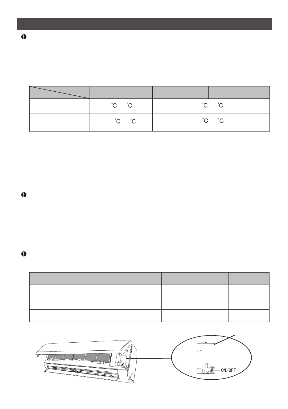
Attempt to use the air conditioner under the temperature beyond the specified range may cause
the air conditioner protection device to start and the air conditioner may fail to operate. Therefore,
try to use the air conditioner in the following temperature conditions.
It beeps briefly once.
It keeps beeping for a while
With the power supply connected, restart the air conditioner after shutdown, or switch it to other
mode during operation, and the air conditioner protection device will start. The compressor will
resume operation after 3 minutes.
Characteristics of heating operation (applicable to Heating pump)
It beeps briefly twice.
Preheating:
When the heating function is enabled, the indoor unit will take 2~5 minutes for preheating, after
that the air conditioner will start heating and blows warm air.
Defrosting:
During heating, when the outdoor unit frosted, the air conditioner will enable the automatic
defrosting function to improve the heating effect. During defrosting, the indoor and outdoor fans
stop running. The air conditioner will resume heating automatically after defrosting finish.
Emergency button:
Open the panel and find the emergency button on the electronic control box when the remote
controller fails . (Always press the emergency button with insulation material.)
Current status
Enter mode
Respond
Operation
Standby
Running
Standby
(Only for heating pump)
Press the emergency button
twice in 3 seconds
Cooling mode
Off mode
Heating mode
Press the emergency button
once
Press the emergency button
once
OPERATION INSTRUCTIONS
Inverter air conditioner:
0 ~30
-20 ~30
Dry
Heating
Cooling
Room temperature
17 32~
Outdoor temperature
Temperature
MODE
-15 ~53
12
INSTRUCTION FOR SERVICING(R32)
1. Check the information in this manual to find out the dimensions of space needed for proper
installation of the device, including the minimum distances allowed compared to adjacent
structures.
2
2. Appliance shall be installed, operated and stored in a room with a floor area larger than 4m .
3. The installation of pipe-work shall be kept to a minimum.
4. The pipe-work shall be protected from physical damage, and shall not be installed in an
2
unventilated space if the space is smaller than 4m .
5. The compliance with national gas regulations shall be observed.
6. The mechanical connections shall be accessible for maintenance purposes.
7. Follow the instructions given in this manual for handling, installing, cleaning, maintaining and
disposing of the refrigerant.
8. Make sure ventilation openings clear of obstruction.
9. Notice: The servicing shall be performed only as recommended by the manufacturer.
10. Warning: The appliance shall be stored in a well-ventilated area where the room size corresponds
to the room area as specified for operation.
11. Warning: The appliance shall be stored in a room without continuously operating open flames
(for example an operating gas appliance) and ignition sources (for example an operating
electric heater).
12. The appliance shall be stored so as to prevent mechanical damage from occurring.
13. It is appropriate that anyone who is called upon to work on a refrigerant circuit should hold a
valid and up-to-date certificate from an assessment authority accredited by the industry and
recognizing their competence to handle refrigerants, in accordance with the assessment
specification recognized in the industrial sector concerned. Service operations should only be
carried out in accordance with the recommendations of the equipment manufacturer.
Maintenance and repair operations that require the assistance of other qualified persons must
be conducted under the supervision of the person competent for the use of flammable
refrigerants.
14. Every working procedure that affects safety means shall only be carried out by competent persons.
15. Warning:
* Do not use means to accelerate the defrosting process or to clean, other than those
recommended by the manufacturer.
* The appliance shall be stored in a room without continuously operating ignition sources
(for example: open flames, an operating gas appliance or an operating electric heater.
* Do not pierce or burn.
* Be aware that refrigerants may not contain an odor.
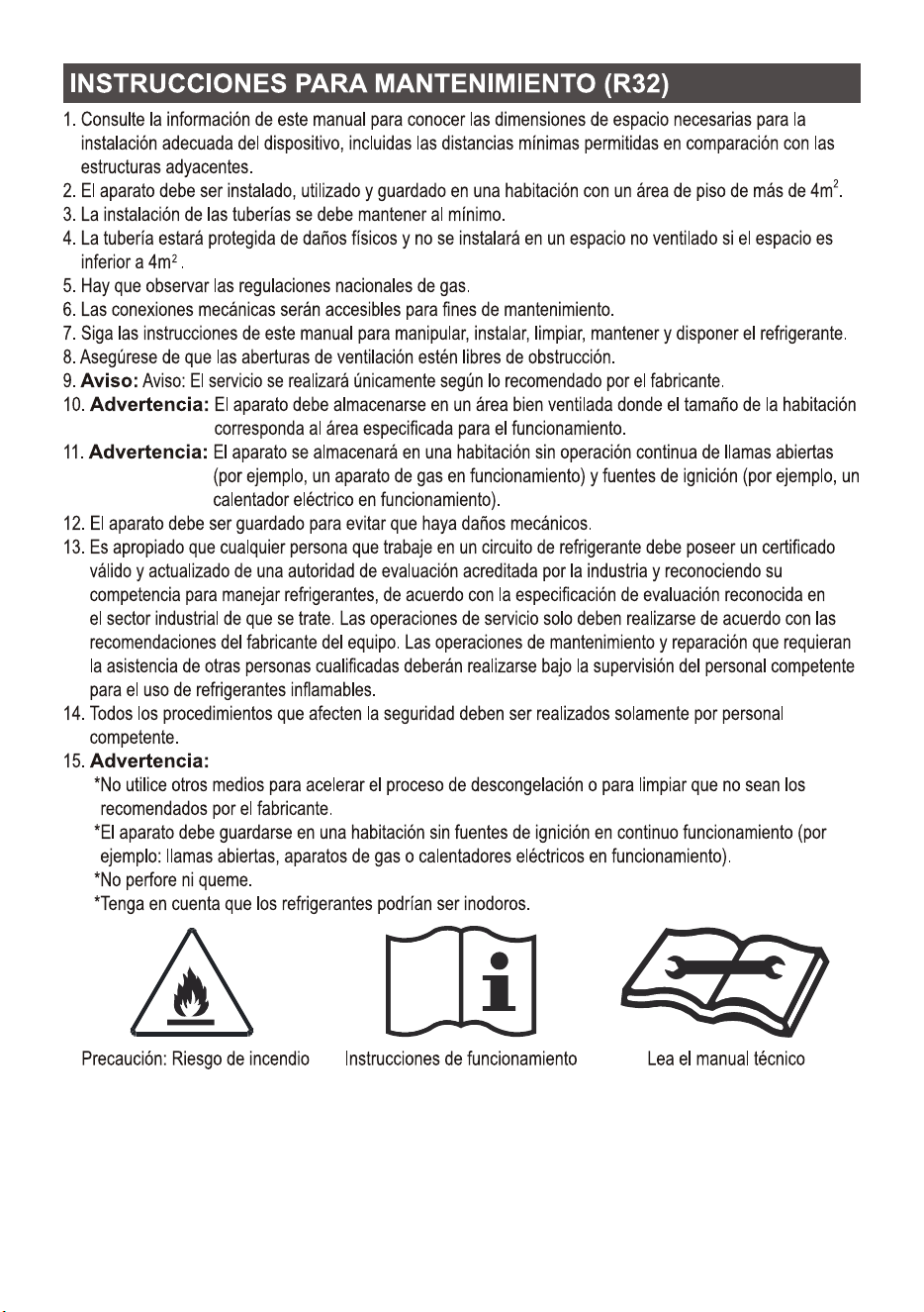
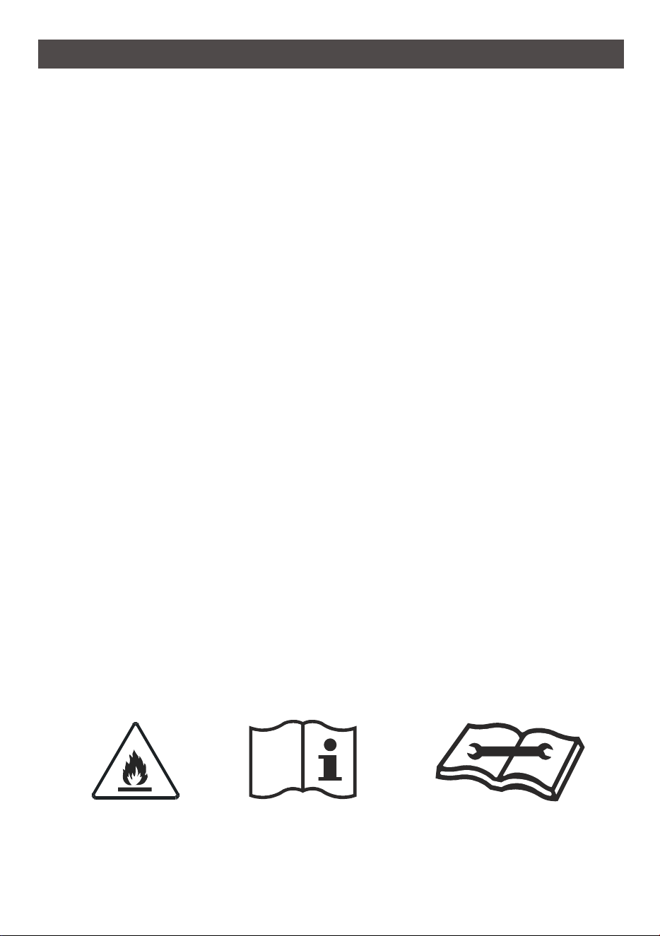
Operating instructions
Read technical manual
Caution: Risk of fire
13

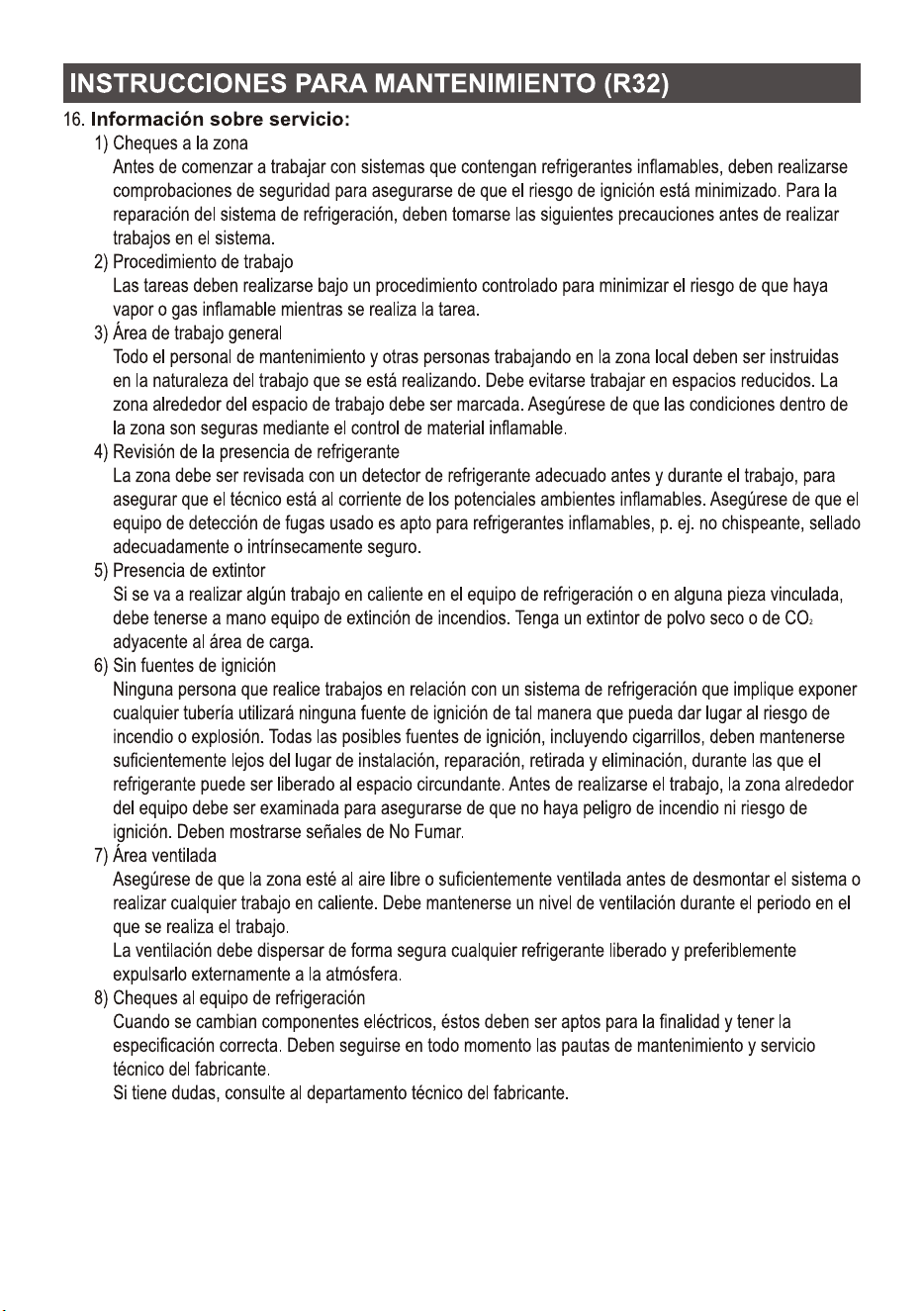
16. Information on servicing:
1) Checks to the area
Prior to beginning work on systems containing flammable refrigerants, safety checks are
necessary to ensure that the risk of ignition is minimized. For repair to the refrigerating system,
the following precautions shall be complied with prior to conducting work on the system.
2) Work procedure
Work shall be undertaken under a controlled procedure so as to minimize the risk of a
flammable gas or vapor being present while the work is being performed.
3) General work area
All maintenance staff and others working in the local area shall be instructed on the nature of
work being carried out. Work in confined spaces shall be avoided. The area around the
workspace shall be sectioned off. Ensure that the conditions within the area have been made
safe by control of flammable material
4) Checking for presence of refrigerant
The area shall be checked with an appropriate refrigerant detector prior to and during work, to
ensure the technician is aware of potentially flammable atmospheres. Ensure that the leak
detection equipment being used is suitable for use with flammable refrigerants, i.e.
non-sparking, adequately sealed or intrinsically safe.
5) Presence of fire extinguisher
If any hot work is to be conducted on the refrigeration equipment or any associated parts,
appropriate fire extinguishing equipment shall be available to hand. Have a dry powder or CO
2
fire extinguisher adjacent to the charging area.
6) No ignition sources
No person carrying out work in relation to a refrigeration system which involves exposing any
pipe work shall use any sources of ignition in such a manner that it may lead to the risk of fire or
explosion. All possible ignition sources, including cigarette smoking, should be kept sufficiently
far away from the site of installation, repairing, removing and disposal, during which refrigerant
can possibly be released to the surrounding space. Prior to work taking place, the area around
the equipment is to be surveyed to make sure that there are no flammable hazards or ignition
risks. No Smoking signs shall be displayed.
7) Ventilated area
Ensure that the area is in the open or that it is adequately ventilated before breaking into the
system or conducting any hot work. A degree of ventilation shall continue during the period
that the work is carried out.
The ventilation should safely disperse any released refrigerant and preferably expel it externally
into the atmosphere.
8) Checks to the refrigeration equipment
Where electrical components are being changed, they shall be fit for the purpose and to the
correct specification. At all times the manufacturer's maintenance and service guidelines shall
be followed.
If in doubt consult the manufacturer's technical department for assistance.
INSTRUCTION FOR SERVICING(R32)
14

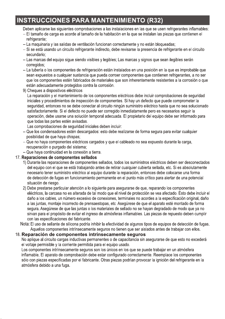
The following checks shall be applied to installations using flammable refrigerants:
-- The charge size is in accordance with the room size within which the refrigerant containing
parts are installed;
-- The ventilation machinery and outlets are operating adequately and are not obstructed;
-- If an indirect refrigerating circuit is being used, the secondary circuit shall be checked for the
presence of refrigerant;
-- Marking to the equipment continues to be visible and legible. Markings and signs that are
illegible shall be corrected;
-- Refrigeration pipe or components are installed in a position where they are unlikely to be
exposed to any substance which may corrode refrigerant containing components, unless the
components are constructed of materials which are inherently resistant to being corroded or
are suitably protected against being so corroded.
9) Checks to electrical devices
Repair and maintenance to electrical components shall include initial safety checks and
component inspection procedures. If a fault exists that could compromise safety, then no
electrical supply shall be connected to the circuit until it is satisfactorily dealt with. If the fault
cannot be corrected immediately but it is necessary to continue operation, an adequate
temporary solution shall be used. This shall be reported to the owner of the equipment so all
parties are advised.
Initial safety checks shall include:
-- That capacitors are discharged: this shall be done in a safe manner to avoid possibility of
sparking;
-- That there no live electrical components and wiring are exposed while charging, recovering
or purging the system;
-- That there is continuity of earth bonding.
17. Repairs to sealed components
1) During repairs to sealed components, all electrical supplies shall be disconnected from the
equipment being worked upon prior to any removal of sealed covers, etc. If it is absolutely
necessary to have an electrical supply to equipment during servicing, then a permanently
operating form of leak detection shall be located at the most critical point to warn of a
potentially hazardous situation.
2) Particular attention shall be paid to the following to ensure that by working on electrical
components, the casing is not altered in such a way that the level of protection is affected. This
shall include damage to cables, excessive number of connections, terminals not made to original
specification, damage to seals, incorrect fitting of glands, etc. Ensure that apparatus is mounted
securely. Ensure that seals or sealing materials have not degraded such that they no longer serve
the purpose of preventing the ingress of flammable atmospheres. Replacement parts shall be in
accordance with the manufacturer's specifications.
NOTE: The use of silicon sealant may inhibit the effectiveness of some types of leak detection
equipment. Intrinsically safe components do not have to be isolated prior to working on them.
18. Repair to intrinsically safe components
Do not apply any permanent inductive or capacitance loads to the circuit without ensuring that
this will not exceed the permissible voltage and current permitted for the equipment in use.
Intrinsically safe components are the only types that can be worked on while live in the presence
of a flammable atmosphere. The test apparatus shall be at the correct rating. Replace components
only with parts specified by the manufacturer. Other parts may result in the ignition of refrigerant
in the atmosphere from a leak.
INSTRUCTION FOR SERVICING(R32)
15

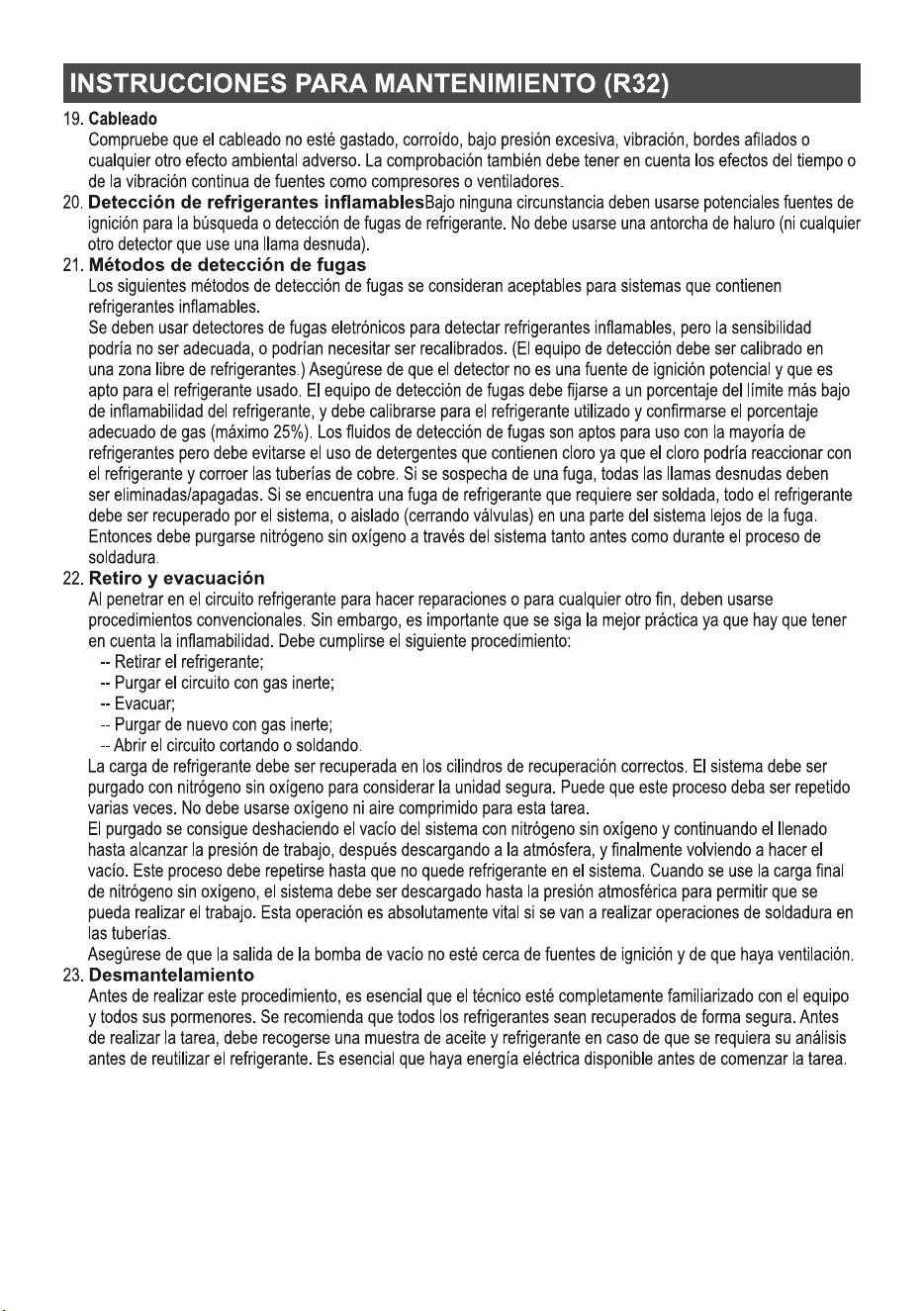
19. Cabling
Check that cabling will not be subject to wear, corrosion, excessive pressure, vibration, sharp
edges or any other adverse environmental effects. The check shall also take into account the
effects of aging or continual vibration from sources such as compressors or fans.
20. Detection of flammable refrigerants
Under no circumstances shall potential sources of ignition be used in the searching for or
detection of refrigerant leaks. A halide torch (or any other detector using a naked flame) shall
not be used.
21. Leak detection methods
The following leak detection methods are deemed acceptable for systems containing flammable
refrigerants.
Electronic leak detectors shall be used to detect flammable refrigerants, but the sensitivity may
not be adequate, or may need re-calibration. (Detection equipment shall be calibrated in a
refrigerant-free area.) Ensure that the detector is not a potential source of ignition and is suitable
for the refrigerant used. Leak detection equipment shall be set at a percentage of the LFL of the
refrigerant and shall be calibrated to the refrigerant employed and the appropriate percentage of
gas (25 % maximum) is confirmed. Leak detection fluids are suitable for use with most refrigerants
but the use of detergents containing chlorine shall be avoided as the chlorine may react with the
refrigerant and corrode the copper pipe-work. If a leak is suspected, all naked flames shall be
removed/ extinguished. If a leakage of refrigerant is found which requires brazing, all of the
refrigerant shall be recovered from the system, or isolated (by means of shut off valves) in a part
of the system remote from the leak. Oxygen free nitrogen (OFN) shall then be purged through the
system both before and during the brazing process.
22. Removal and evacuation
When breaking into the refrigerant circuit to make repairs or for any other purpose conventional
procedures shall be used. However, it is important that best practice is followed since
inflammability is a consideration. The following procedure shall be adhered to:
-- Remove refrigerant;
-- Purge the circuit with inert gas;
-- Evacuate;
-- Purge again with inert gas;
-- Open the circuit by cutting or brazing.
The refrigerant charge shall be recovered into the correct recovery cylinders. The system shall be
flushed with OFN to render the unit safe. This process may need to be repeated several times.
Compressed air or oxygen shall not be used for this task.
Flushing shall be achieved by breaking the vacuum in the system with OFN and continuing to fill
until the working pressure is achieved, then venting to atmosphere, and finally pulling down to a
vacuum. This process shall be repeated until no refrigerant is within the system. When the final
OFN charge is used, the system shall be vented down to atmospheric pressure to enable work to
take place. This operation is absolutely vital if brazing operations on the pipe-work are to take
place.
Ensure that the outlet for the vacuum pump is not close to any ignition sources and there is
ventilation available.
23. Decommissioning
Before carrying out this procedure, it is essential that the technician is completely familiar with
the equipment and all its detail. It is recommended good practice that all refrigerants are
recovered safely. Prior to the task being carried out, an oil and refrigerant sample shall be taken
in case analysis is required prior to re-use of reclaimed refrigerant. It is essential that electrical
power is available before the task is commenced.
INSTRUCTION FOR SERVICING(R32)
16

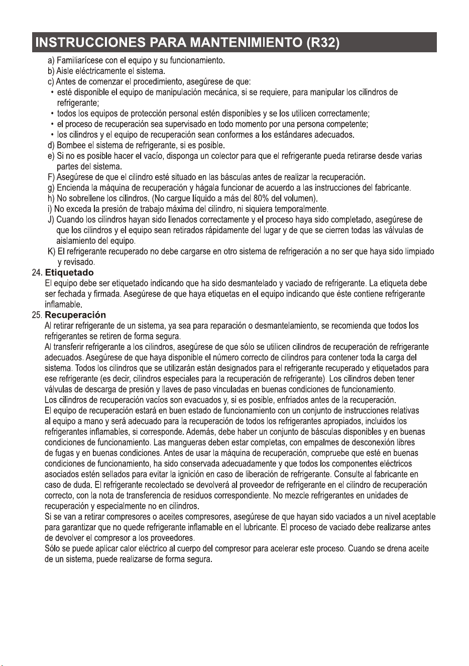
a) Become familiar with the equipment and its operation.
b) Isolate system electrically.
c) Before attempting the procedure, ensure that:
. mechanical handling equipment is available, if required, for handling refrigerant cylinders;
. all personal protective equipment is available and being used correctly;
. the recovery process is supervised at all times by a competent person;
. recovery equipment and cylinders conform to the appropriate standards.
d) Pump down refrigerant system, if possible.
e) If a vacuum is not possible, make a manifold so that refrigerant can be removed from various
parts of the system.
F) Make sure that cylinder is situated on the scales before recovery takes place.
g) Start the recovery machine and operate in accordance with manufacturer's instructions.
h) Do not overfill cylinders. (No more than 80 % volume liquid charge).
i) Do not exceed the maximum working pressure of the cylinder, even temporarily.
J) When the cylinders have been filled correctly and the process completed, make sure that the
cylinders and the equipment are removed from site promptly and all isolation valves on the
equipment are closed off.
K) Recovered refrigerant shall not be charged into another refrigeration system unless it has been
cleaned and checked.
24. Labeling
Equipment shall be labeled stating that it has been de-commissioned and emptied of refrigerant.
The label shall be dated and signed. Ensure that there are labels on the equipment stating the
equipment contains flammable refrigerant.
25. Recovery
When removing refrigerant from a system, either for servicing or decommissioning, it is
recommended good practice that all refrigerants are removed safely.
When transferring refrigerant into cylinders, ensure that only appropriate refrigerant recovery
cylinders are employed. Ensure that the correct number of cylinders for holding the total system
charge are available. All cylinders to be used are designated for the recovered refrigerant and
labeled for that refrigerant (i.e. Special cylinders for the recovery of refrigerant). Cylinders shall
be complete with pressure-relief valve and associated shut-off valves in good working order.
Empty recovery cylinders are evacuated and, if possible, cooled before recovery occurs.
The recovery equipment shall be in good working order with a set of instructions concerning the
equipment that is at hand and shall be suitable for the recovery of all appropriate refrigerants
including, when applicable, flammable refrigerants. In addition, a set of calibrated weighing scales
shall be available and in good working order. Hoses shall be complete with leak-free disconnect
couplings and in good condition. Before using the recovery machine, check that it is in satisfactory
working order, has been properly maintained and that any associated electrical components are
sealed to prevent ignition in the event of a refrigerant release. Consult manufacturer if in doubt.
The recovered refrigerant shall be returned to the refrigerant supplier in the correct recover
cylinder, and the relevant waste transfer note arranged. Do not mix refrigerants in recovery units
and especially not in cylinders.
If compressors or compressor oils are to be removed, ensure that they have been evacuated to an
acceptable level to make certain that flammable refrigerant does not remain within the lubricant.
The evacuation process shall be carried out prior to returning the compressor to the suppliers.
Only electric heating to the compressor body shall be employed to accelerate this process. When
oil is drained from a system, it shall be carried out safely.
INSTRUCTION FOR SERVICING(R32)
17
1. The air conditioner must be installed by professional personnel and the Installation manual is used
only for the professional installation personnel! The installation specifications should be subject to
our after-sale service regulations.
2. When filling the combustible refrigerant, any of your rude operations may cause serious injury or
injuries to human body and objects.
3. A leak test must be done after the installation completed.
4. It is a must to do the safety inspection before maintaining or repairing an air conditioner using
combustible refrigerant in order to ensure that the fire risk is reduced to minimum.
5. It is necessary to operate the machine under a controlled procedure in order to ensure that any
risk arising from the combustible gas or vapor during the operation is reduced to minimum.
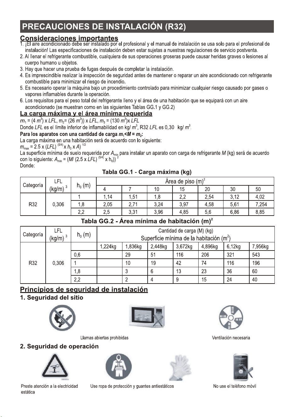
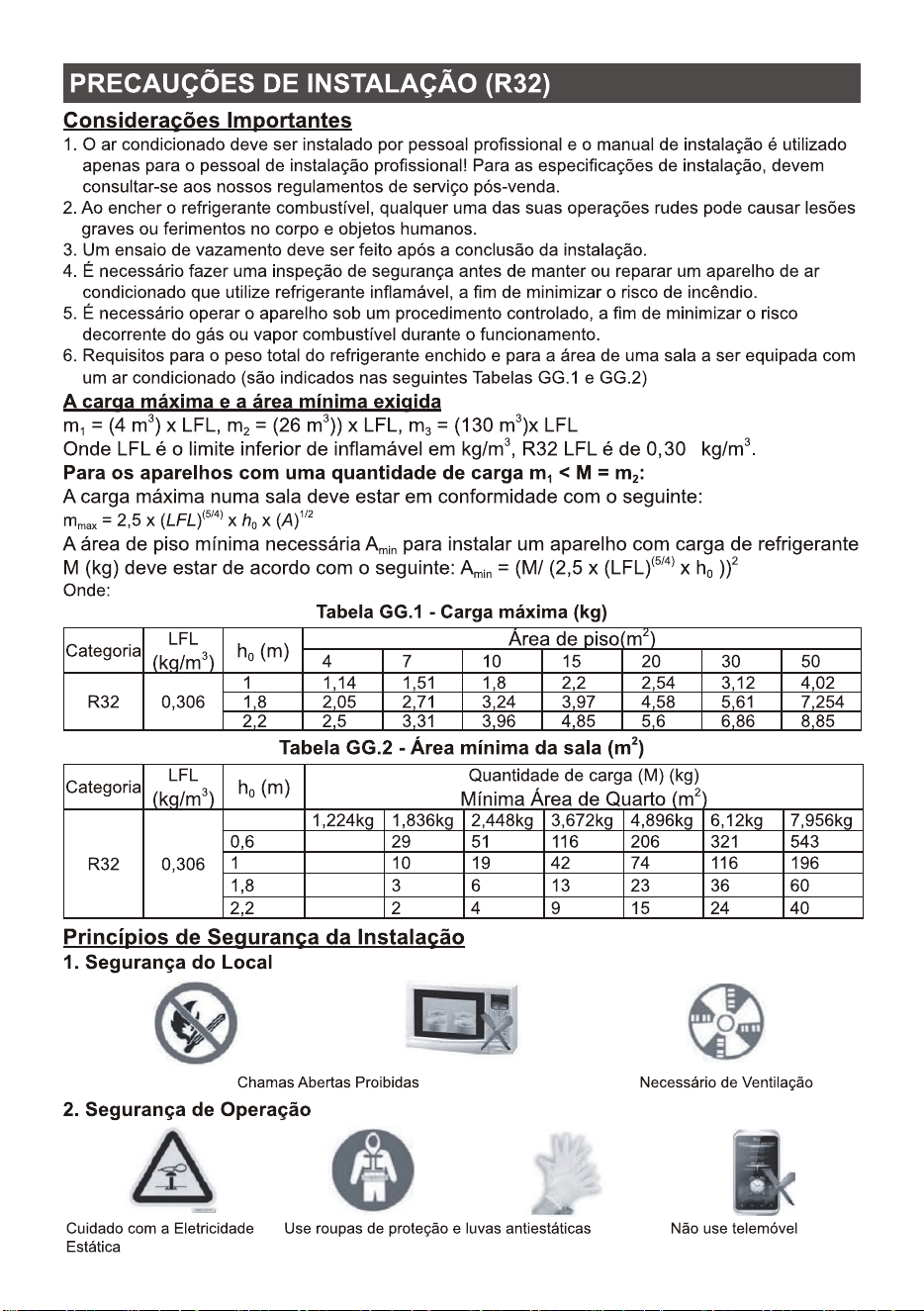
6. Requirements for the total weight of filled refrigerant and the area of a room to be equipped with
an air conditioner (are shown as in the following Tables GG.1 and GG.2)
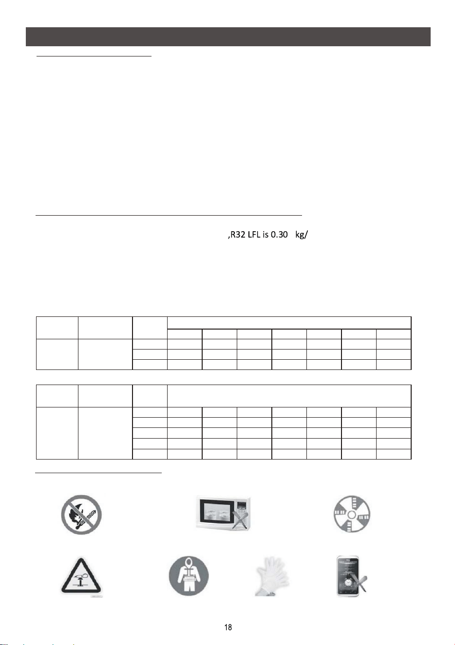
1. Site Safety
Open Flames Prohibited
Ventilation Necessary
2. Operation Safety
Mind Static Electricity
The maximum charge and the required minimum floor area
Installation Safety Principles
33 3
m = (4 m ) x LFL , m = (26 m )) x LFL, m = (130 m )x LFL
12 3
33
Where LFL is the lower flammable limit in kg/ m
6
m.
For the appliances with a charge amount m < M = m :
12
The maximum charge in a room shall be in accordance with the following:
(5/4) 1/2
m = 2.5 x (LFL) x h x (A)
max 0
The required minimum floor area Amin to install an appliance with refrigerant charge M (kg)
(5/4) 2
shall be in accordance with following: A = (M/ (2.5 x (LFL)x h))
min 0
Where:
Important Considerations
Table GG.1 - Maximum charge (kg)
Category
R32
0.306
3
LFL (kg/m)
h(m)
0
2
Floor area (m)
4 7 10 15 20 30 50
1 1.14 1.51 1.8 2.2 2.54 3.12 4.02
1.8 2.05 2.71 3.24 3.97 4.58 5.61 7.254
2.2 2.5 3.31 3.96 4.85 5.6 6.86 8.85
Charge amount (M) (kg)
2
Minimum room area (m)
0.6
1
1.8
2.2
2
Table GG.2 - Minimum room area (m)
Category
R32
0.306
3
LFL (kg/m)
h(m)
0
1.224kg 1.836kg 2.448kg 3.672kg 4.896kg 6.12kg 7.956kg
29 51 116 206 321 543
10 19 42 74 116 196
3 6 13 23 36 60
2 4 9 15 24 40
Must wear protective clothing
and anti-static gloves
Don`t use mobile phone
INSTALLATION PRECAUTIONS(R32)
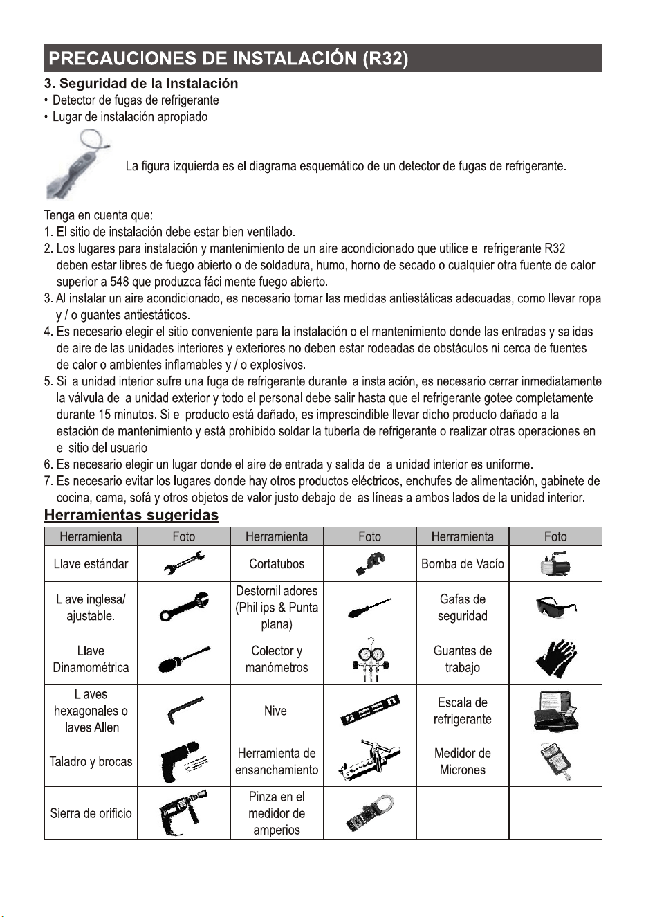
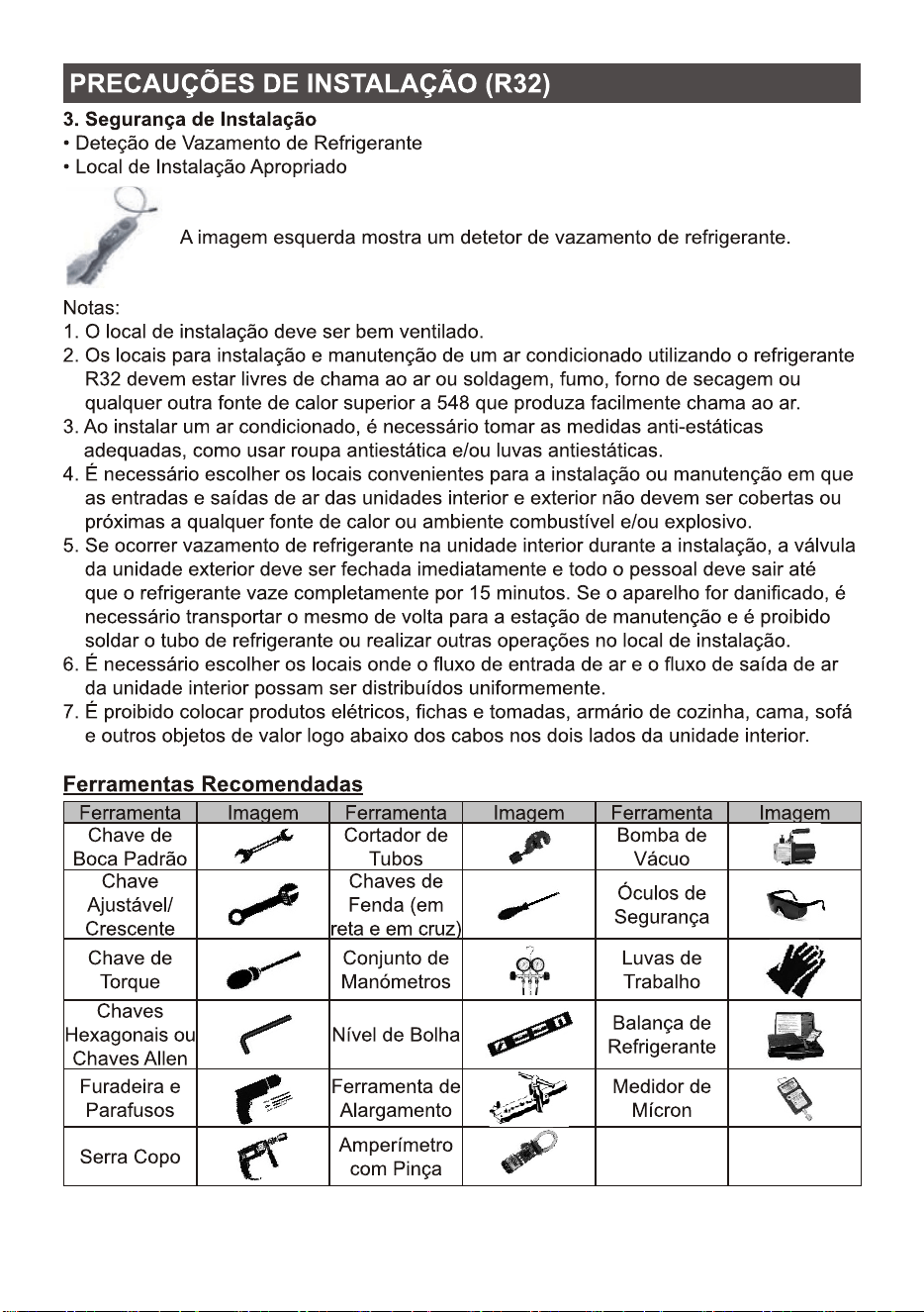
3. Installation Safety
Refrigerant Leak Detector
Appropriate Installation Location
The left picture is the schematic diagram of a refrigerant leak detector.
Please note that:
1. The installation site should be well-ventilated.
2. The sites for installing and maintaining an air conditioner using Refrigerant R32 should be free
from open fire or welding, smoking, drying oven or any other heat source higher than 548 which
easily produces open fire.
3. When installing an air conditioner, it is necessary to take appropriate anti-static measures such
as wear anti-static clothing and/or gloves.
4. It is necessary to choose the site convenient for installation or maintenance wherein the air inlets
and outlets of the indoor and outdoor units should be not surrounded by obstacles or close to any
heat source or combustible and/or explosive environment.
5. If the indoor unit suffers refrigerant leak during the installation, it is necessary to immediately turn
off the valve of the outdoor unit and all the personnel should go out till the refrigerant leaks
completely for 15 minutes. If the product is damaged, it is a must to carry such damaged product
back to the maintenance station and it is prohibited to weld the refrigerant pipe or conduct other
operations on the user's site.
6. It is necessary to choose the place where the inlet and outlet air of the indoor unit is even.
7. It is necessary to avoid the places where there are other electrical products, power switch plugs
and sockets, kitchen cabinet, bed, sofa and other valuables right under the lines on two sides of
the indoor unit.
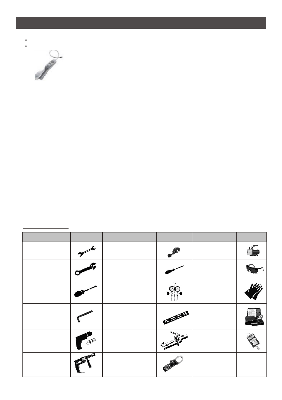
Suggested Tools
Tool
Picture
Standard Wrench
Adjustable/
Crescent Wrench
Torque Wrench
Hex Keys or
Allen Wrenches
Drill & Drill Bits
Hole Saw
Pipe Cutter
Screw drivers
(Phillips & Flat blade)
Manifold and
Gauges
Level
Flaring tool
Clamp on Amp
Meter
Vacuum Pump
Safety Glasses
Work Gloves
Refrigerant Scale
Micron Gauge
Tool
Picture
Tool
Picture
INSTALLATION PRECAUTIONS(R32)
19
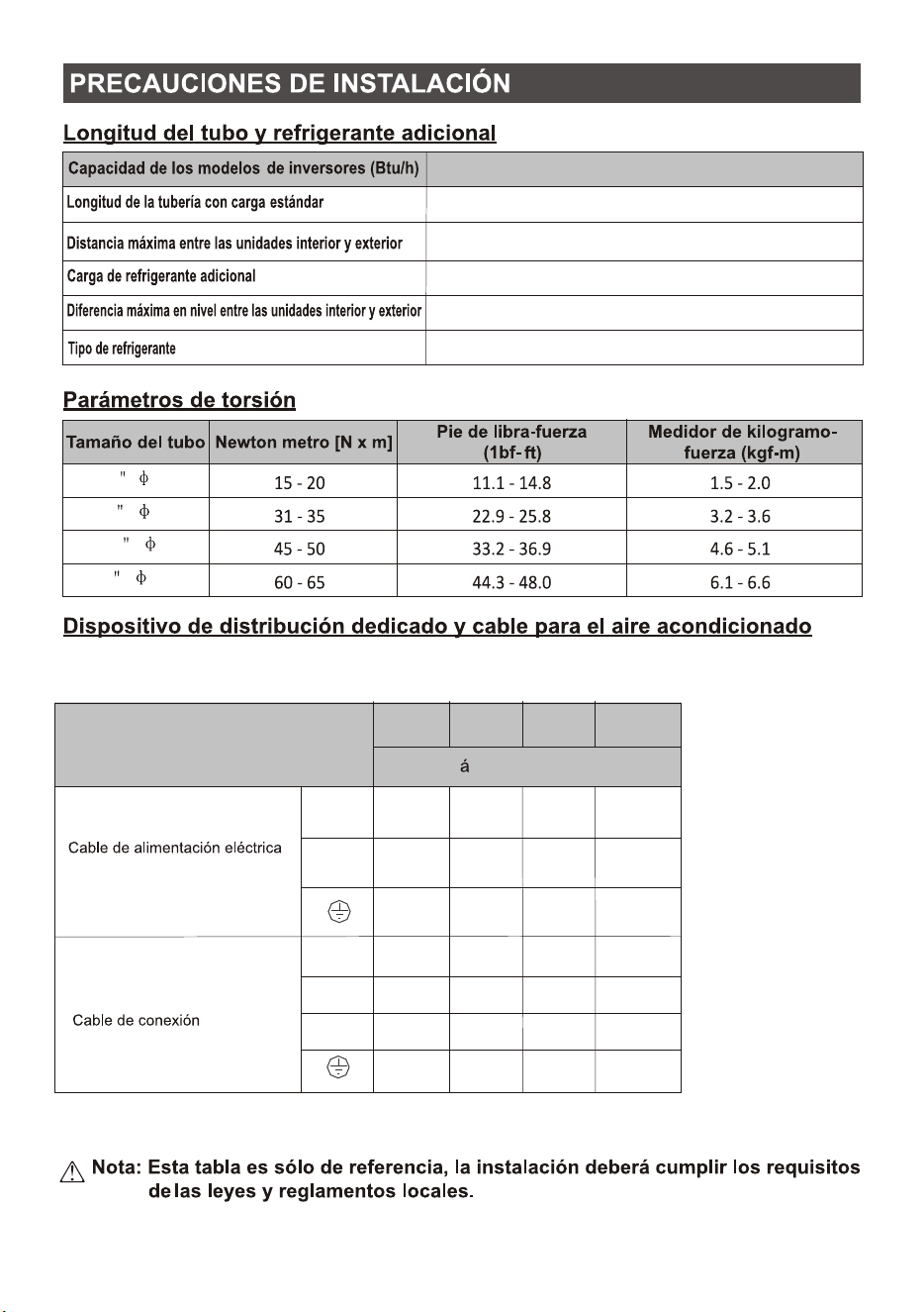
INSTALLATION PRECAUTIONS
Torque Parameters
Dedicated Distribution Device and Wire for Air Conditioner
Note: This table is only for reference, the installation shall meet the requirements of local laws
and regulations.
Pipe Length and Additional Refrigerant
Inverter Models Capacity (Btu/h)
9K-12K (For each indoor)
Lenght of pipe with standard charge
Maximum distance between indoor and outdoor unit
Additional refrigerant charge
Max. diff. in level between indoor and outdoor unit
Type of refrigerant
R32
15m
10m
15g/m
5m
2
2.5mm
INVERTER TYPE
MODEL capacity (Btu/h)
2
2.5mm
2
2.5mm
2
2.5mm
2
2.5mm
2
2.5mm
2
0.75mm
2
0.75mm
2
0.75mm
2
0.75mm
2
0.75mm
2
0.75mm
2
0.75mm
2
0.75mm
9k
12k
18k
27k
Power supply cable
(on outdoor)
Connection cable
N
L
1
N
L
sectional area
20
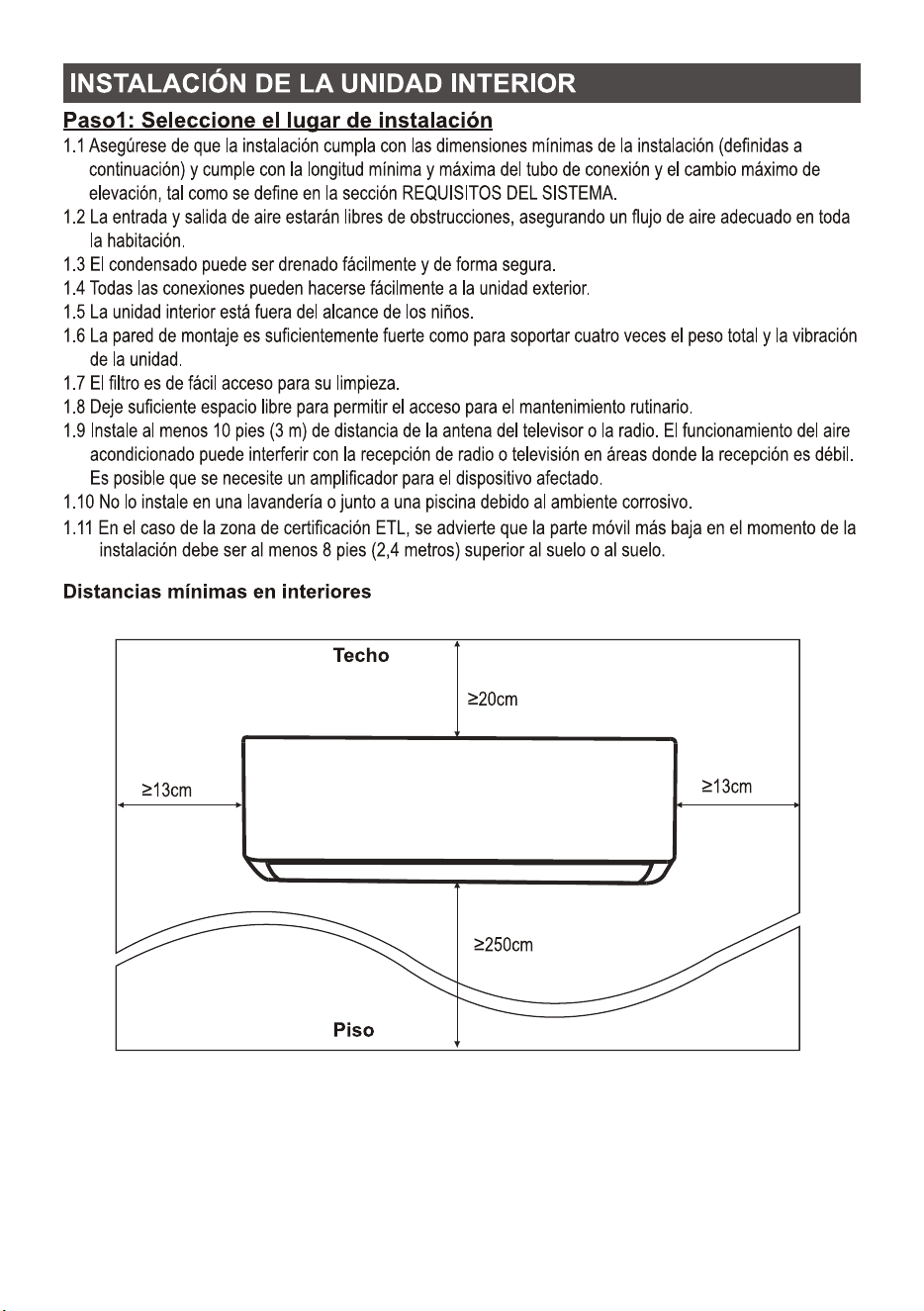
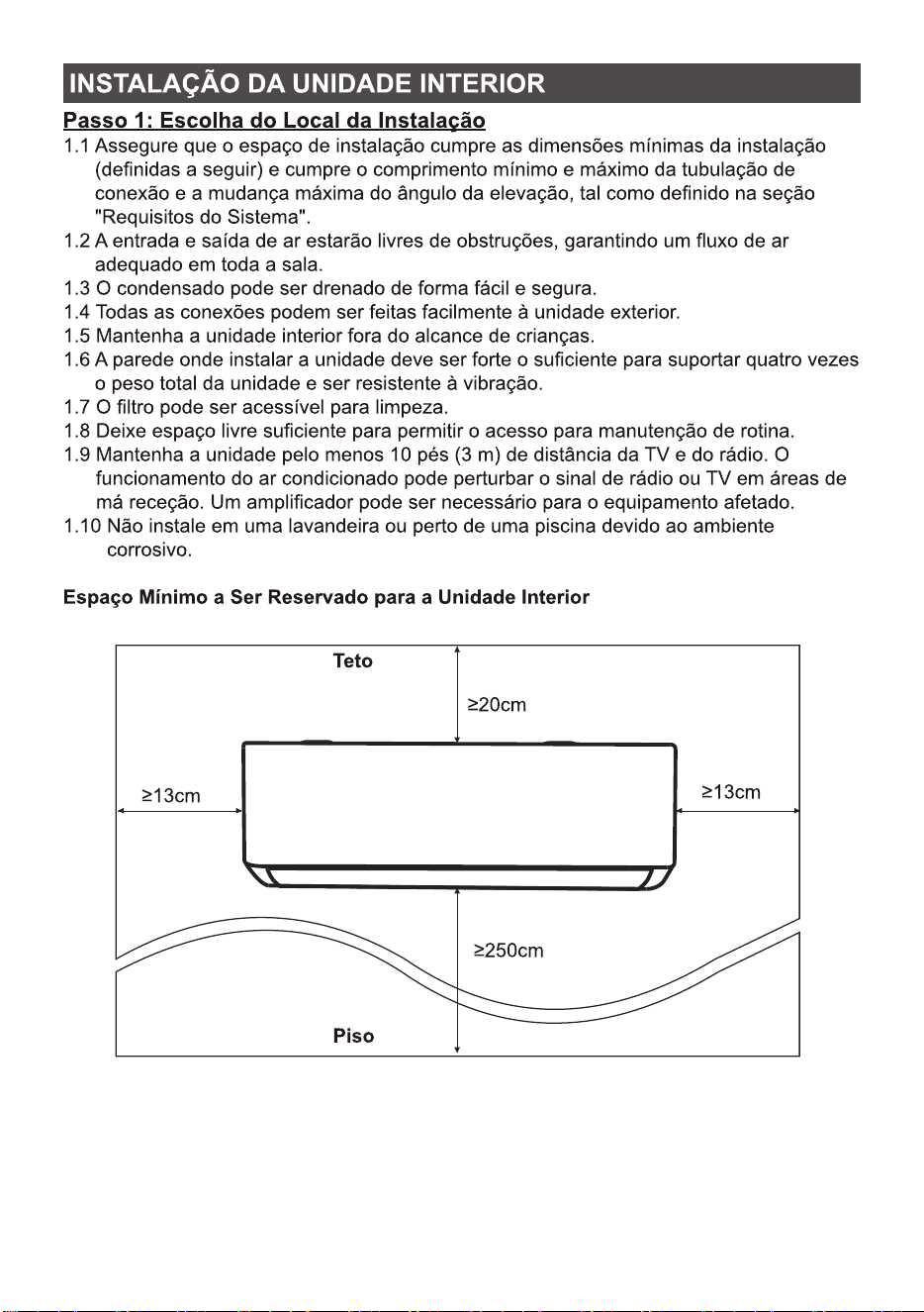
1.1 Ensure the installation complies with the installation minimum dimensions (defined below) and
meets the minimum and maximum connecting piping length and maximum change in elevation
as defined in the System Requirements section.
1.2 Air inlet and outlet will be clear of obstructions, ensuring proper airflow throughout the room.
1.3 Condensate can be easily and safely drained.
1.4 All connections can be easily made to outdoor unit.
1.5 Indoor unit is out of reach of children.
1.6 A mounting wall strong enough to withstand four times the full weight and vibration of the unit.
1.7 Filter can be easily accessed for cleaning.
1.8 Leave enough free space to allow access for routine maintenance.
1.9 Install at least 10 ft. (3 m) away from the antenna of TV set or radio. Operation of the air
conditioner may interfere with radio or TV reception in areas where reception is weak. An
amplifier may be required for the affected device.
1.10 Do not install in a laundry room or by a swimming pool due to the corrosive environment.
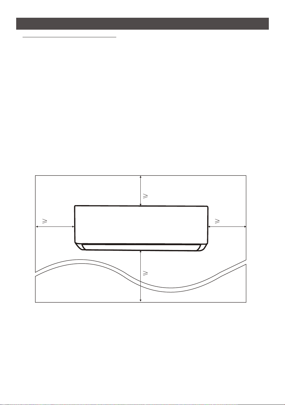
Minimum Indoor Clearances
Step1: Select Installation location
Floor
Ceiling
13cm 13cm
250cm
20cm
INDOOR UNIT INSTALLATION
21
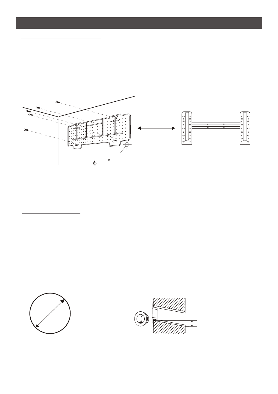
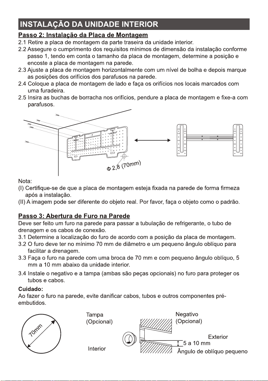
Step3: Drill Wall Hole
70mm
Wall sleeve
(Optional)
5-10mm
Wall sleeve Cover
(Optional)
Outdoor
Indoor
Small bolique angle
INDOOR UNIT INSTALLATION
Step2: Install Mounting Plate
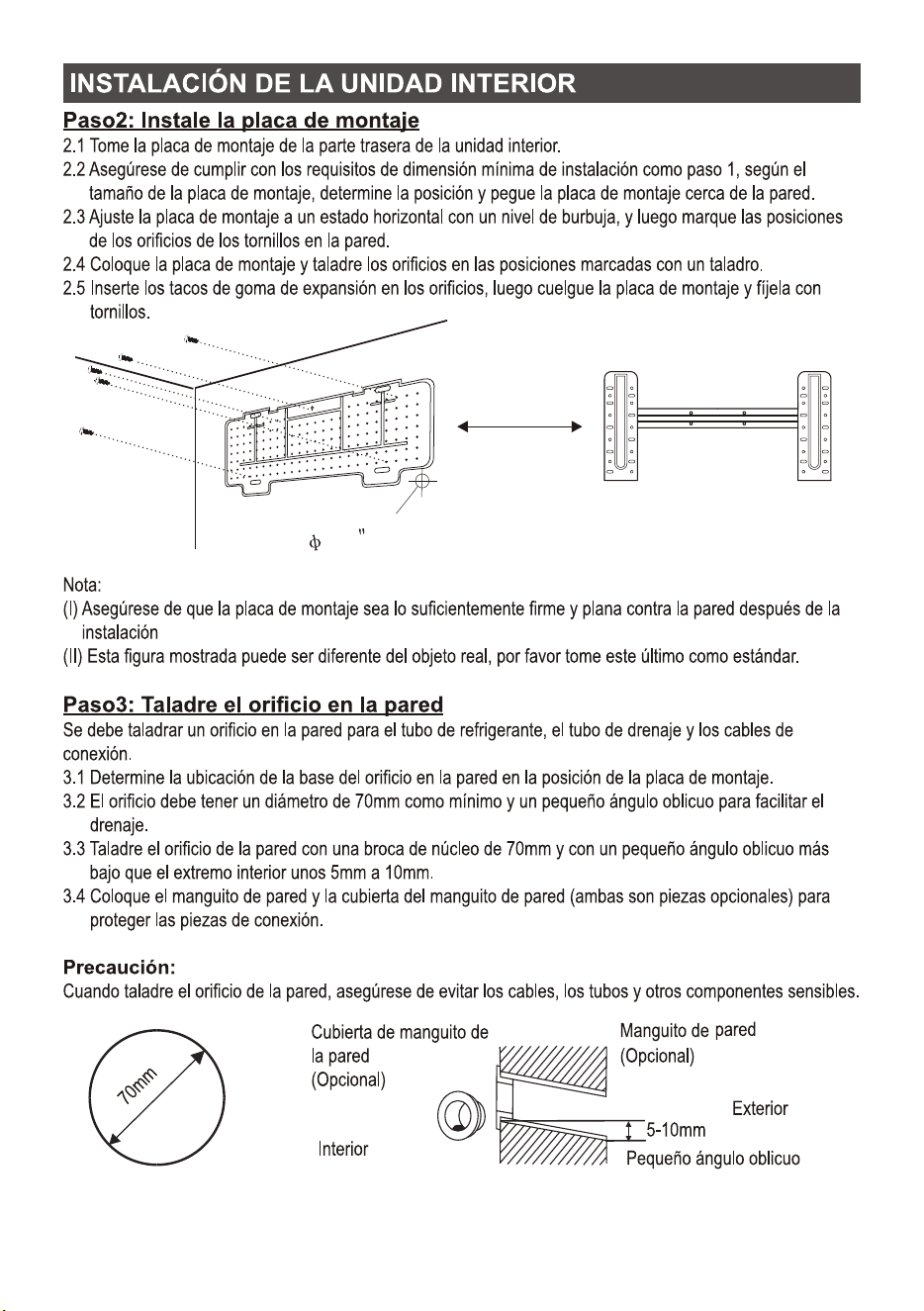
2.1 Take the mounting plate from the back of indoor unit.
2.2 Ensure to meet the minimum installation dimension requirements as step 1, according to the size
of mounting plate, determine the position and stick the mounting plate close to the wall.
2.3 Adjust the mounting plate to a horizontal state with a spirit level, then mark out the screw hole
positions on the wall.
2.4 Put down the mounting plate and drill holes in the marked positions with drill.
2.5 Insert expansion rubber plugs into the holes, then hang the mounting plate and fix it with screws.
A hole in the wall should be drilled for refrigerant piping ,the drainage pipe, and connecting cables.
3.1 Determine the location of wall hole base on the position of mounting plate.
3.2 The hole should be have a 70mm diameter at least and a small oblique angle to facilitate drainage.
3.3 Drill the wall hole with 70mm core drill and with small oblique angle lower than the indoor end
about 5mm to 10mm.
3.4 Place the wall sleeve and wall sleeve cover(both are optional parts) to protect the connection parts.
Caution:
When drill the wall hole, maker sure to avoid wires, plumbing and other sensitive components.
Note:
(I) Make sure the mounting plate is firm enough and flat against the wall after installation.
(II) This figure shown may be different from the actual object, please take the latter as the standard.
2.8 (70mm)
22
INDOOR UNIT INSTALLATION
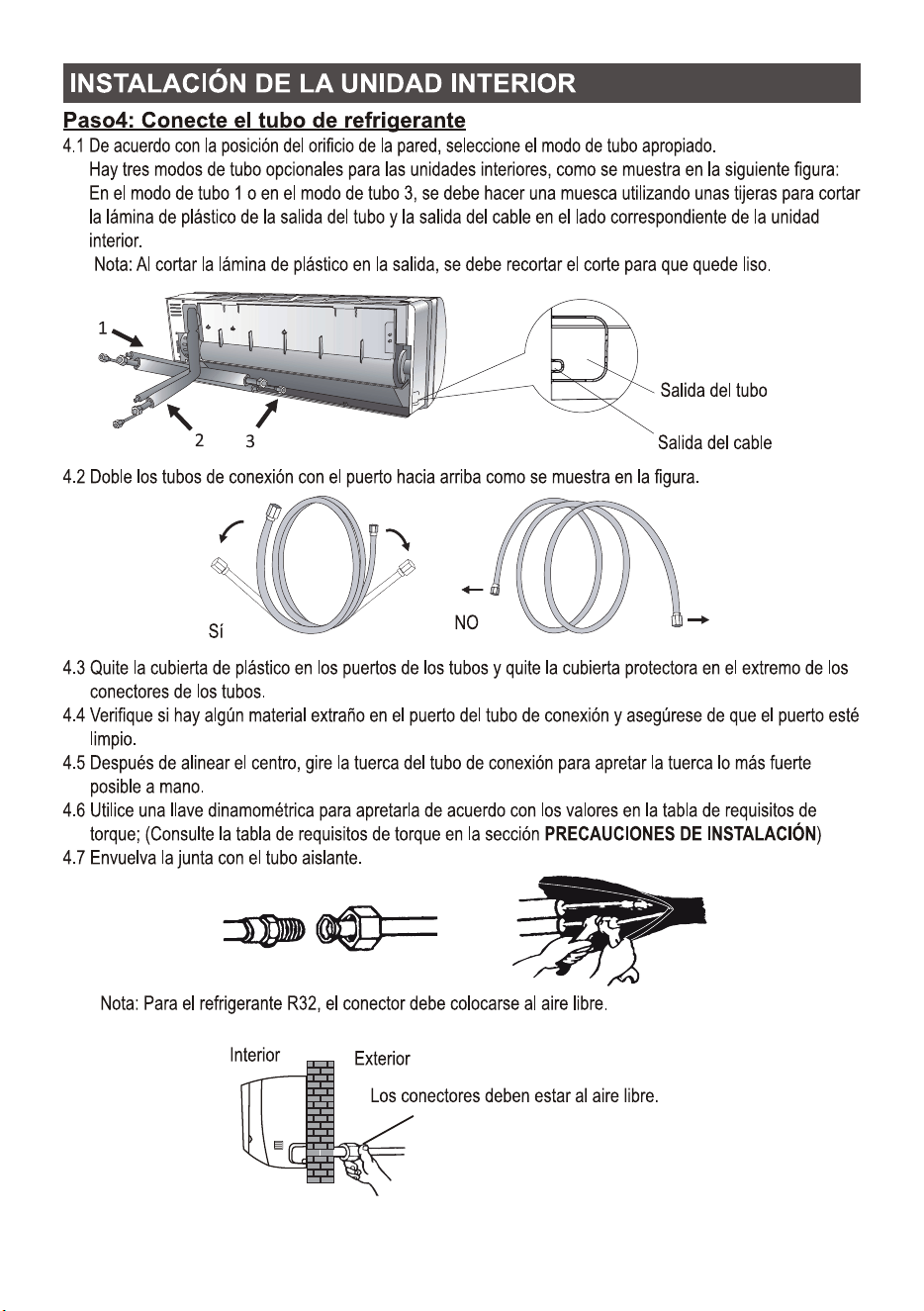
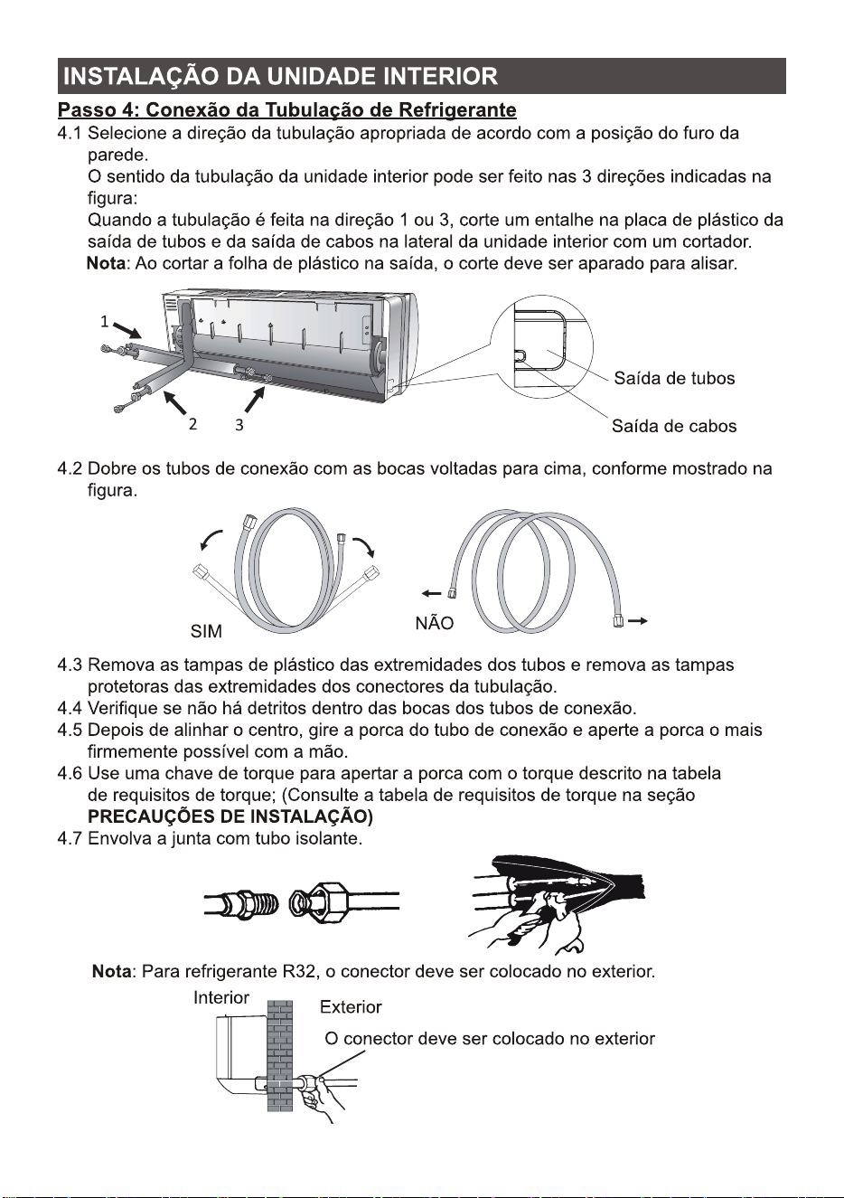
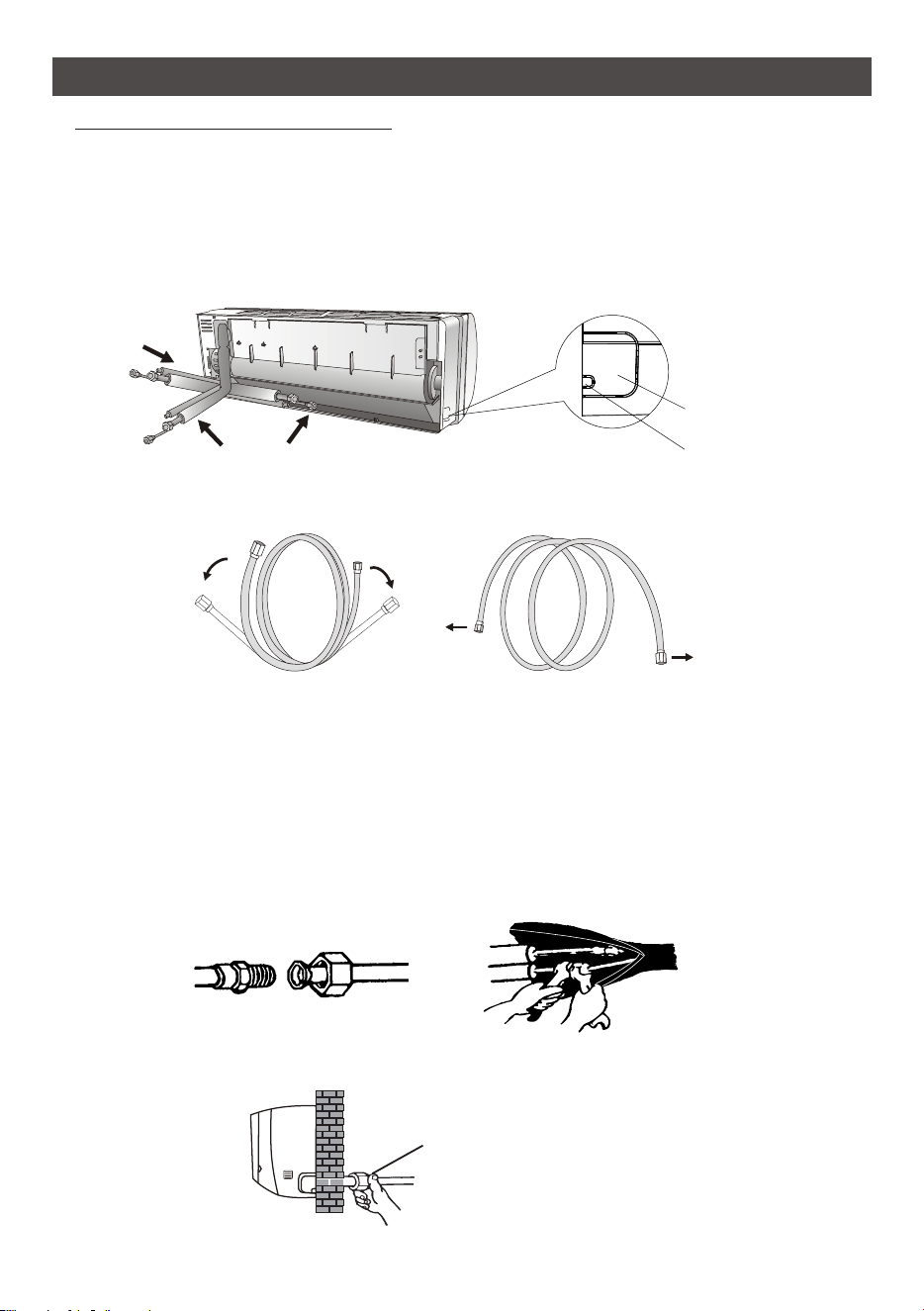
4.1 According to the wall hole position, select the appropriate piping mode.
There are three optional piping modes for indoor units as shown in the figure below:
In Piping Mode 1 or Piping Mode 3, a notch should be made by using scissors to cut the plastic
sheet of piping outlet and cable outlet on the corresponding side of the indoor unit.
Note: When cutting off the plastic sheet at the outlet, the cut should be trimmed to smooth.
3
2
1
Piping outlet
Cable outlet
Step4: Connecting Refrigerant Pipe
4.2 Bending the connecting pipes with the port facing up as shown in the figure.
NO
YES
4.3 Take off the plastic cover in the pipe ports and take off the protective cover on the end of piping
connectors.
4.4 Check whether there is any sundry on the port of the connecting pipe and make ensure the port
is clean.
4.5 After align the center, rotate the nut of the connecting pipe to tighten the nut as tightly as possible
by hand.
4.6 Use a torque wrench to tighten it according to the torque values in the torque requirements table;
(Refer to the torque requirements table on section INSTALLATION PRECAUTIONS)
4.7 Wrap the joint with the insulation pipe.
Note: For R32 refrigerant, the connector should be placed outdoors.
The connector should be outdoor
OutdoorIndoor
23
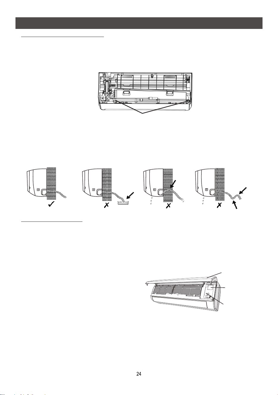
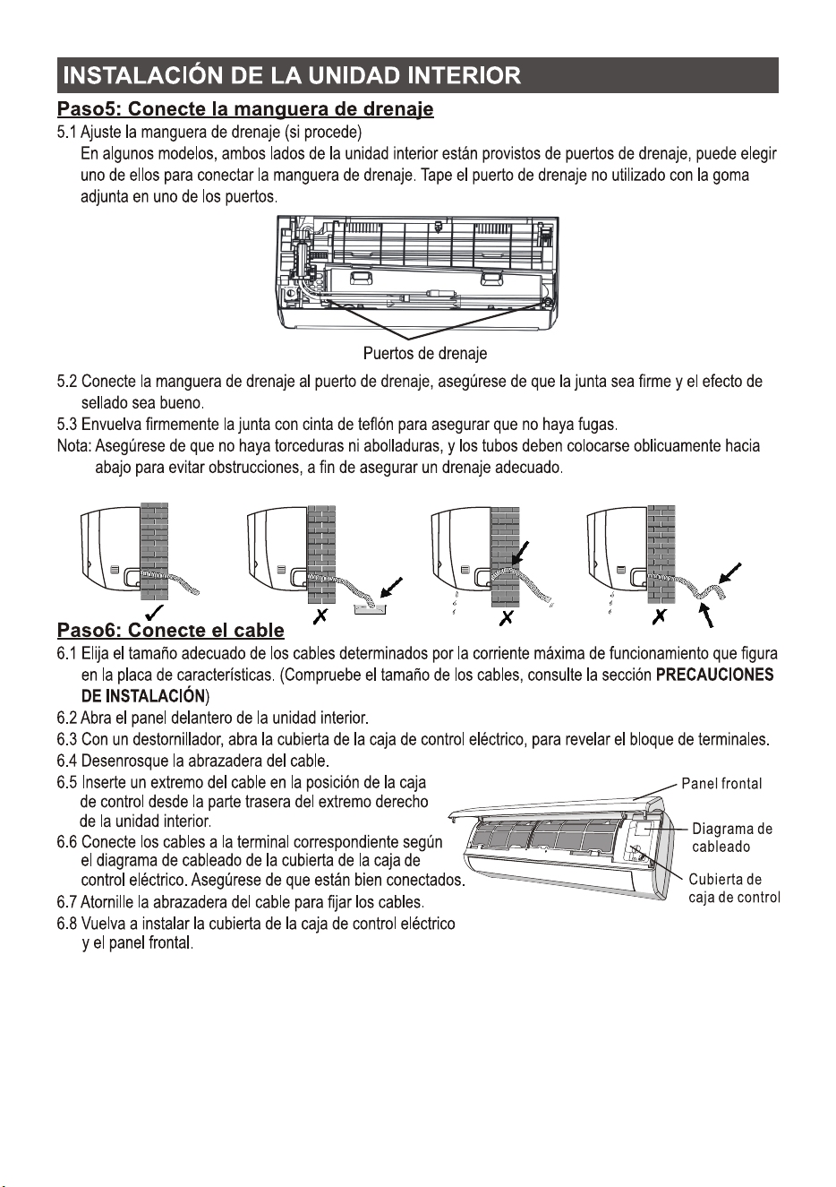
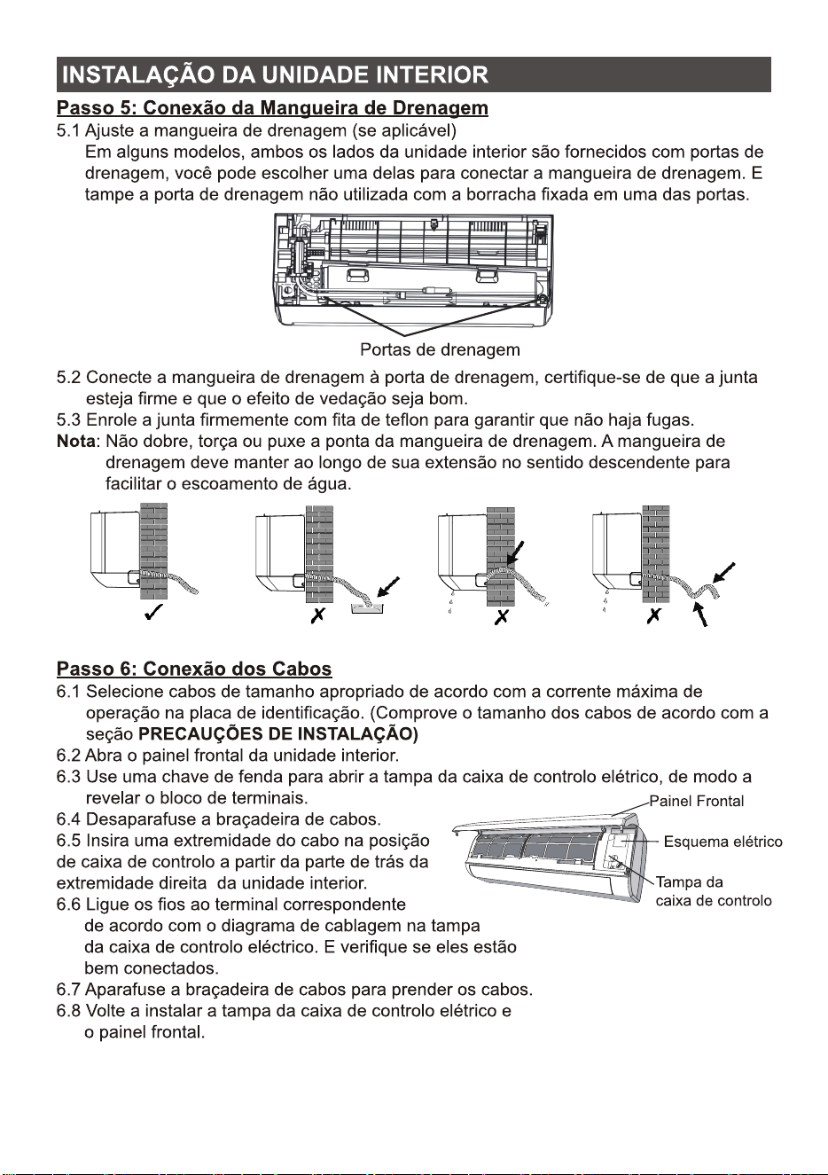
5.1 Adjust the drainage hose(if applicable)
In some model, both sides of the indoor unit are provided with drainage ports, you can choose
one of them to attache the drainage hose. And plug the unused drain port with the rubber
attached in one of the ports.
Step5: Connect Drainage Hose
5.2 Connect the drainage hose to the drainage port, ensure the joint is firm and the sealing
effect is good.
5.3 Wrap the joint firmly with teflon tape to ensure no leaks.
Note: Make sure there is no twists or dents, and the pipes should be placed obliquely
downward to avoid blockage, to ensure proper drainage.
Step6: Connect Wiring
6.1 Choose the right cables size determined by the maximum operating current on the nameplate.
(Check the cables size refer to section INSTALLATION PRECAUTIONS)
6.2 Open the front panel of indoor unit.
6.3 Use a screwdriver, open the electric control box cover, to reveal the terminal block.
6.4 Unscrew the cable clamp.
6.5 Insert one end of the cable into the position
of control box from the back of the right end
of the indoor unit.
6.6 Connect the wires to corresponding terminal
according to the wiring diagram on the electric
control box cover. And make sure that they are
well connected.
6.7 Screw the cable clamp to fasten the cables.
6.8 Reinstall the electric control box cover and
front panel.
INDOOR UNIT INSTALLATION
Drainage ports
Control box
cover
Wiring diagram
Front panel
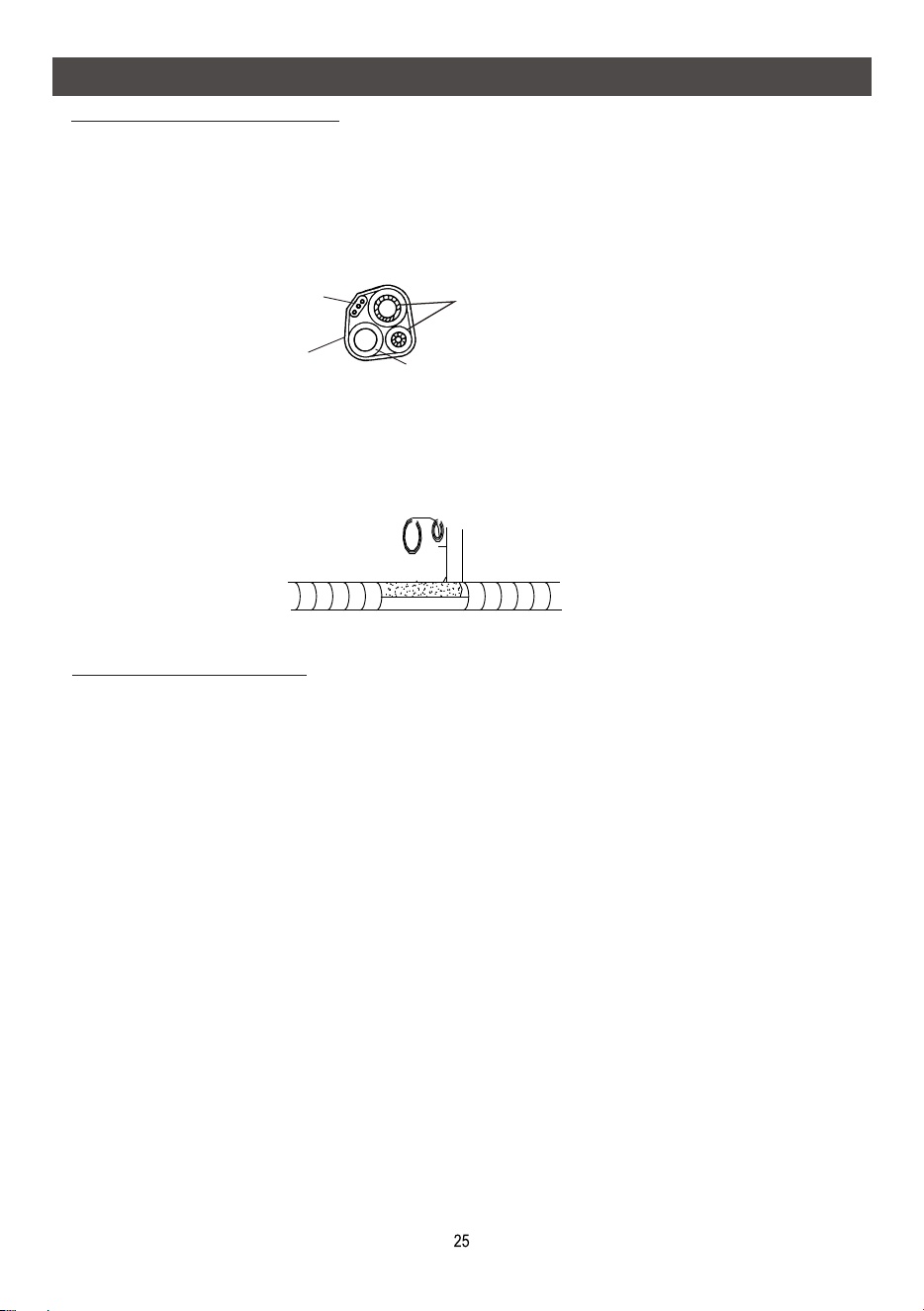
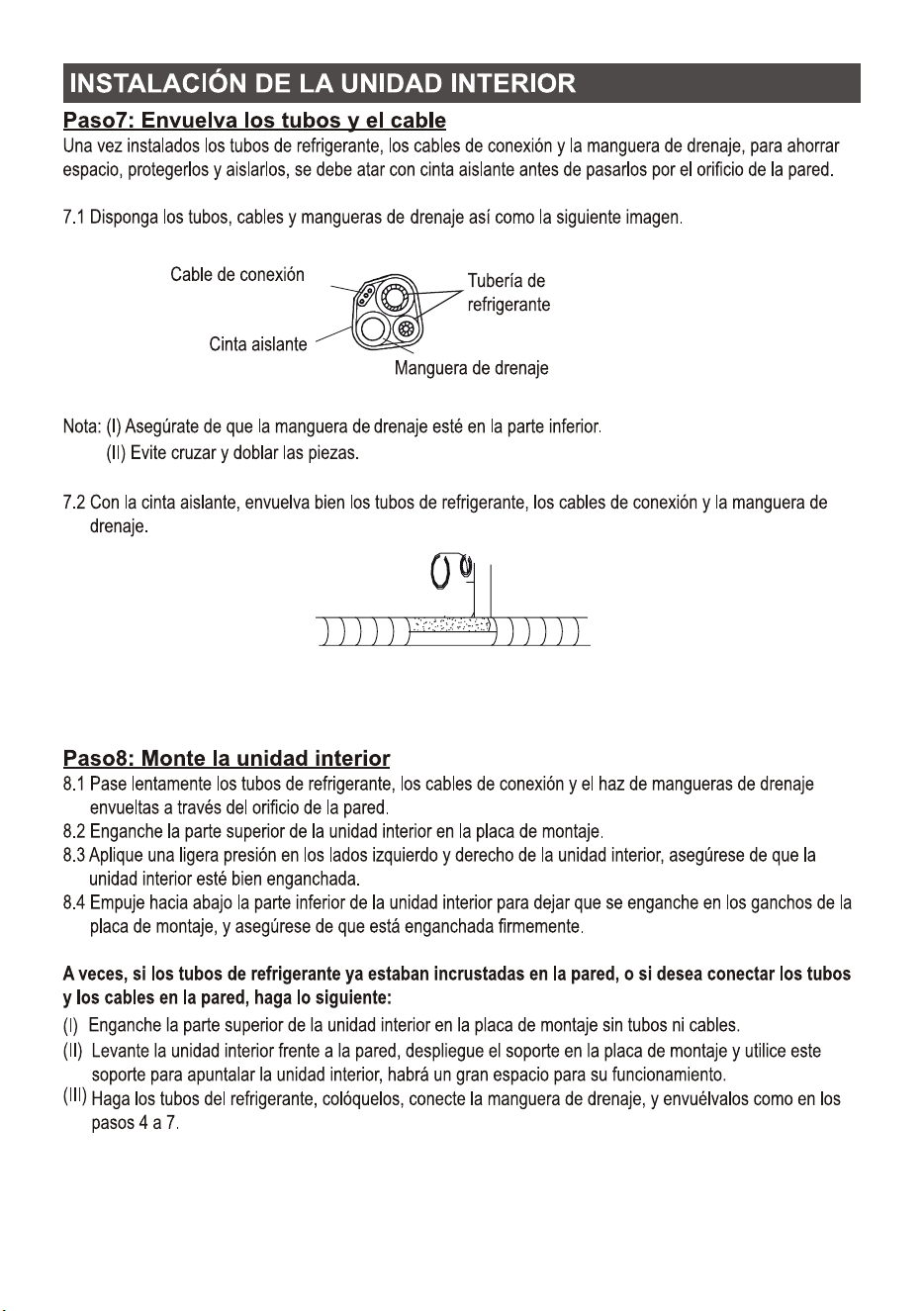
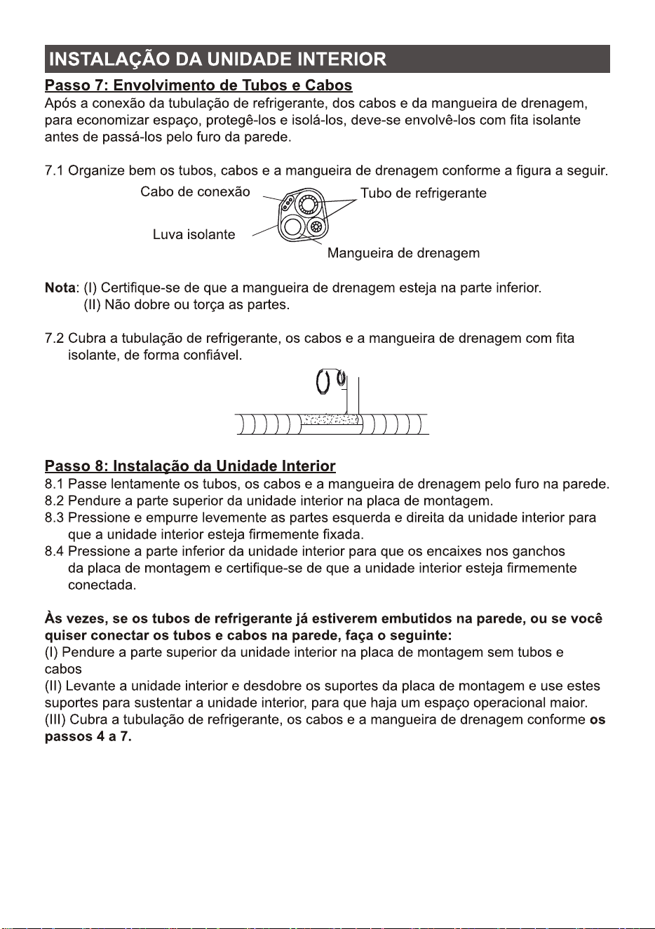
Step7: Wrap Piping and Cable
Connecting wiring
Refrigerant piping
Drainage hose
Insulation tape
After the refrigerant pipes, connecting wires and drainage hose are all installed, in order to save
space, protect and insulate them, it must be bundle with insulating tape before passing them through
the wall hole.
Note: Make sure the drainage hose is at the bottom.
A
(I)
(II) void crossing and bending of parts.
7.2 Using the insulating tape wrap the refrigerant pipes, connecting wires and drainage hose
together tightly.
Step8: Mount Indoor Unit
8.1 Slowly pass the refrigerant pipes, connecting wires and drainage hose wrapped bundle through
the wall hole.
8.2 Hook the top of indoor unit on the mounting plate.
8.3 Apply slight pressure to the left and right sides of the indoor unit, make sure the indoor unit is
hooked firmly.
8.4 Push down the bottom of indoor unit to let the snaps onto the hooks of the mounting plate, and
make sure it is hooked firmly.
Sometimes, if the refrigerant pips were already embedded in the wall, or if you want to connecting
the pips and wires on the wall, do as below:
(I) Hook the top of the indoor unit on the mounting plate without piping and wiring.
(II) Lift the indoor unit opposite the wall, unfold the bracket on the mounting plate, and use this
bracket to prop up the indoor unit, there will be a big space for operation.
(III) Do the refrigerant piping, wiring, connect drainage hose, and wrap them as Step 4 to 7.
INDOOR UNIT INSTALLATION
7.1 Arrange the pipes ,cables and drainage hose well as the following picture.
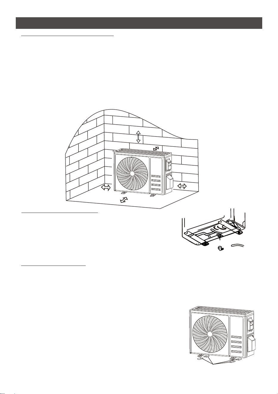
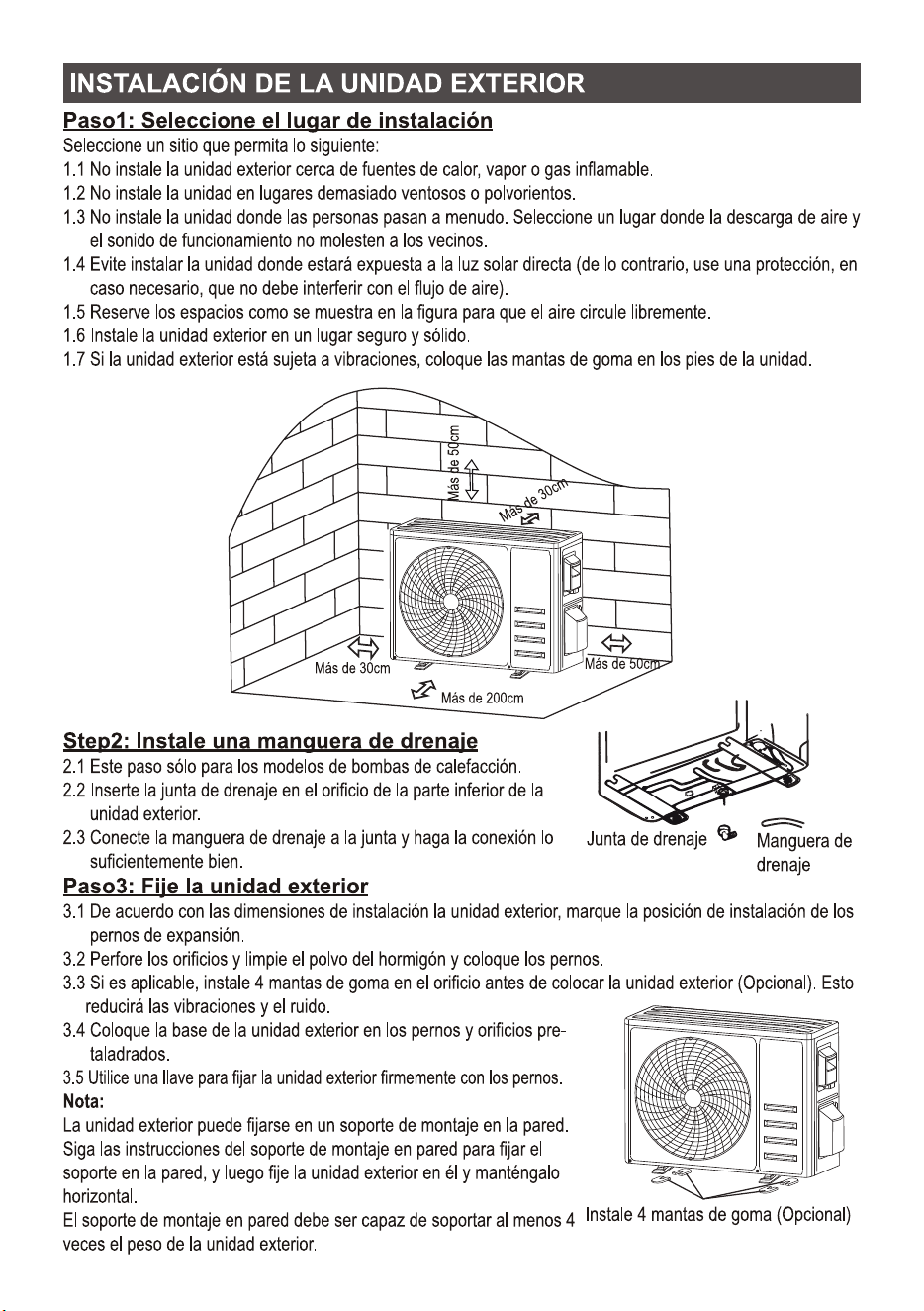
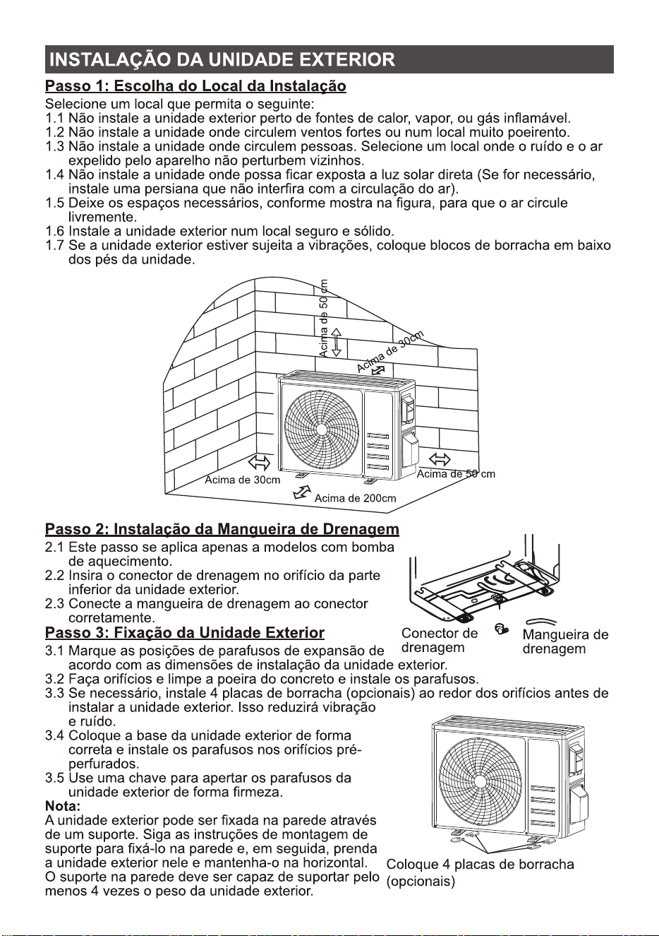
Step1: Select Installation Location
Select a site that allows for the following:
1.1 Do not install the outdoor unit near sources of heat, steam or flammable gas.
1.2 Do not install the unit in too windy or dusty places.
1.3 Do not install the unit where people often pass. Select a place where the air discharge and
operating sound will not disturb the neighbors.
1.4 Avoid installing the unit where it will be exposed to direct sunlight ( other wise use a protection,
if necessary, that should not interfere with the air flow).
1.5 Reserve the spaces as shown in the picture for the air to circulate freely.
1.6 Install the outdoor unit in a safe and solid place.
1.7 If the outdoor unit is subject to vibration, place rubber blankets onto the feet of the unit.
Step2: Install Drainage Hose
Step3: Fix Outdoor Unit
Drainage joint
Drainage hose
OUTDOOR UNIT INSTALLATION
Over 200cm
Over 30cm
Over 50cm
Ove
r 3
0c
m
Over 50cm
Install 4 rubber blankets (Optional)
2.1 This step only for heating pump models.
2.2 Insert the drainage joint to the hole at the bottom
of the outdoor unit.
2.3 Connect the drainage hose to the joint and make the
connection well enough.
3.1 According to the
The outdoor unit can be fixed on a wall-mounting bracket.
Follow the instruction of the wall-mounting bracket to
wall-mounting bracket
wall-mounting bracket must be able to support at least
4 times of the weight of outdoor unit.
outdoor unit installation dimensions to mark the installation position for
expansion bolts .
3.2 Drill holes and clean the concrete dust and place the bolts .
3.3 If applicable install 4 rubber blankets on the hole before place the outdoor unit (Optional).
This will reduce vibrations and noise.
3.4 Place the outdoor unit base on the bolts and pre-drilled holes.
3.5 Use wrench to fix the outdoor unit firmly with bolts.
Note:
fix
the on the wall, and then fasten the
outdoor unit on it and keep it horizontal.
The
26
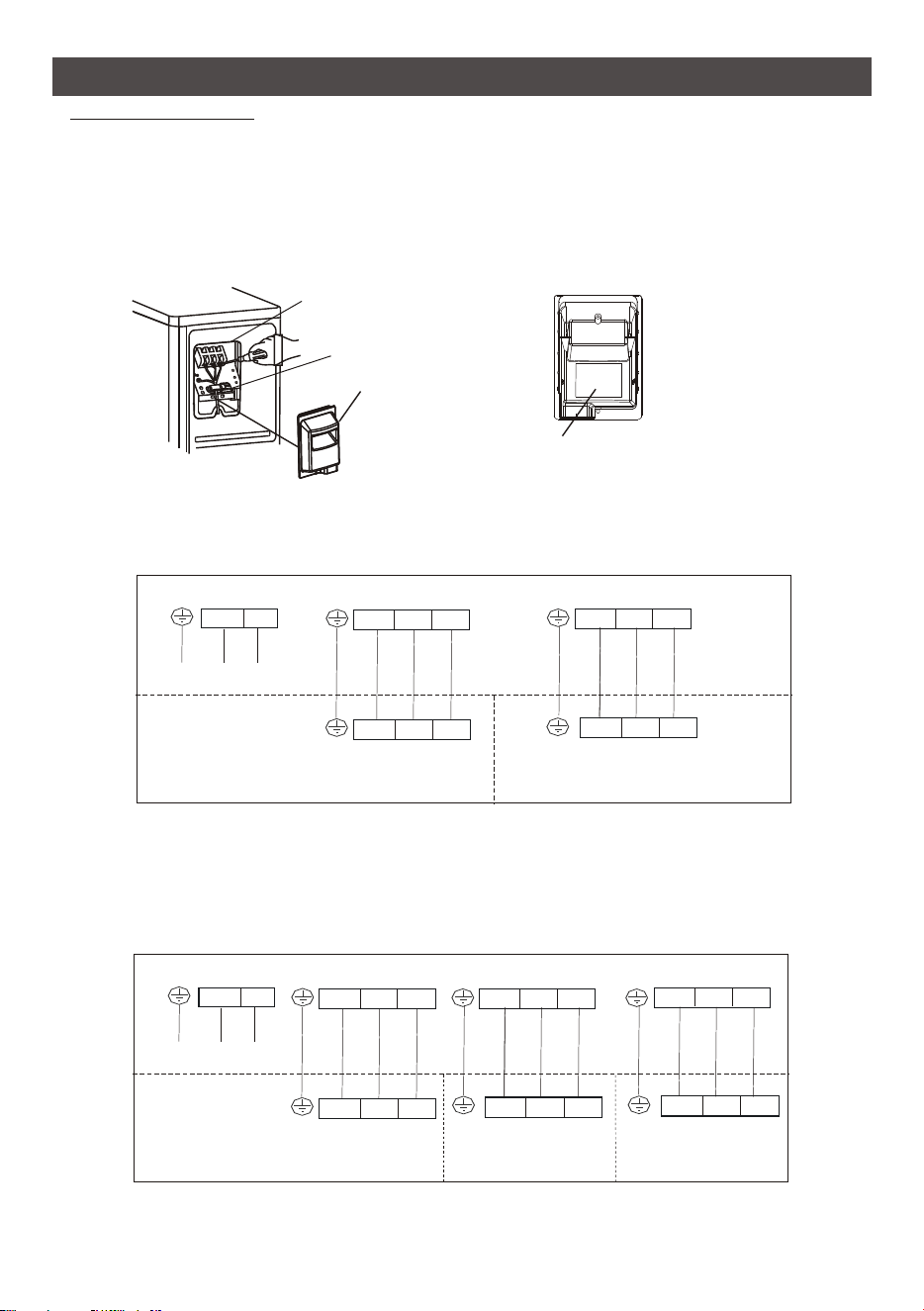
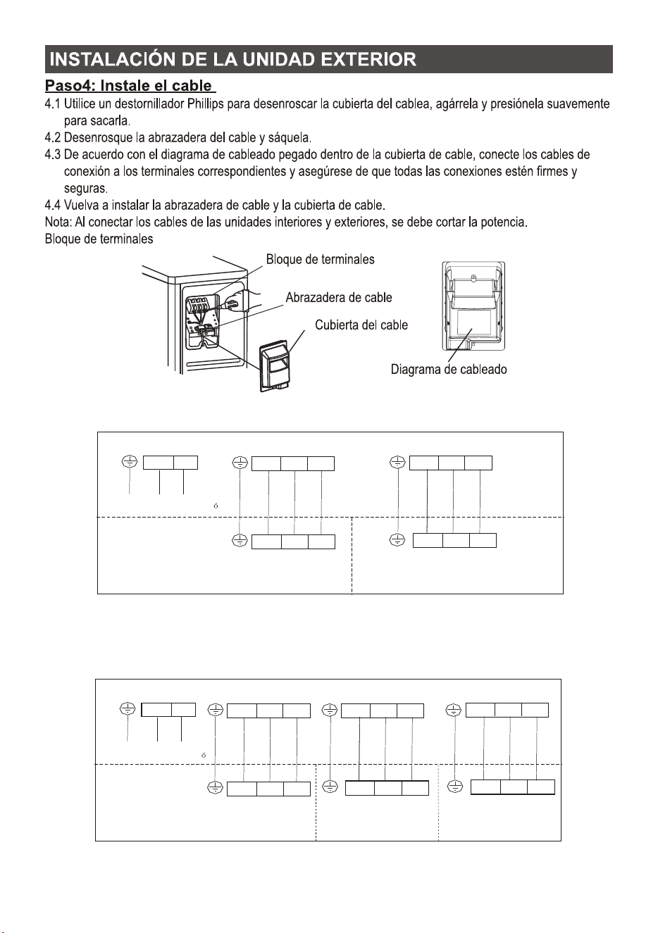
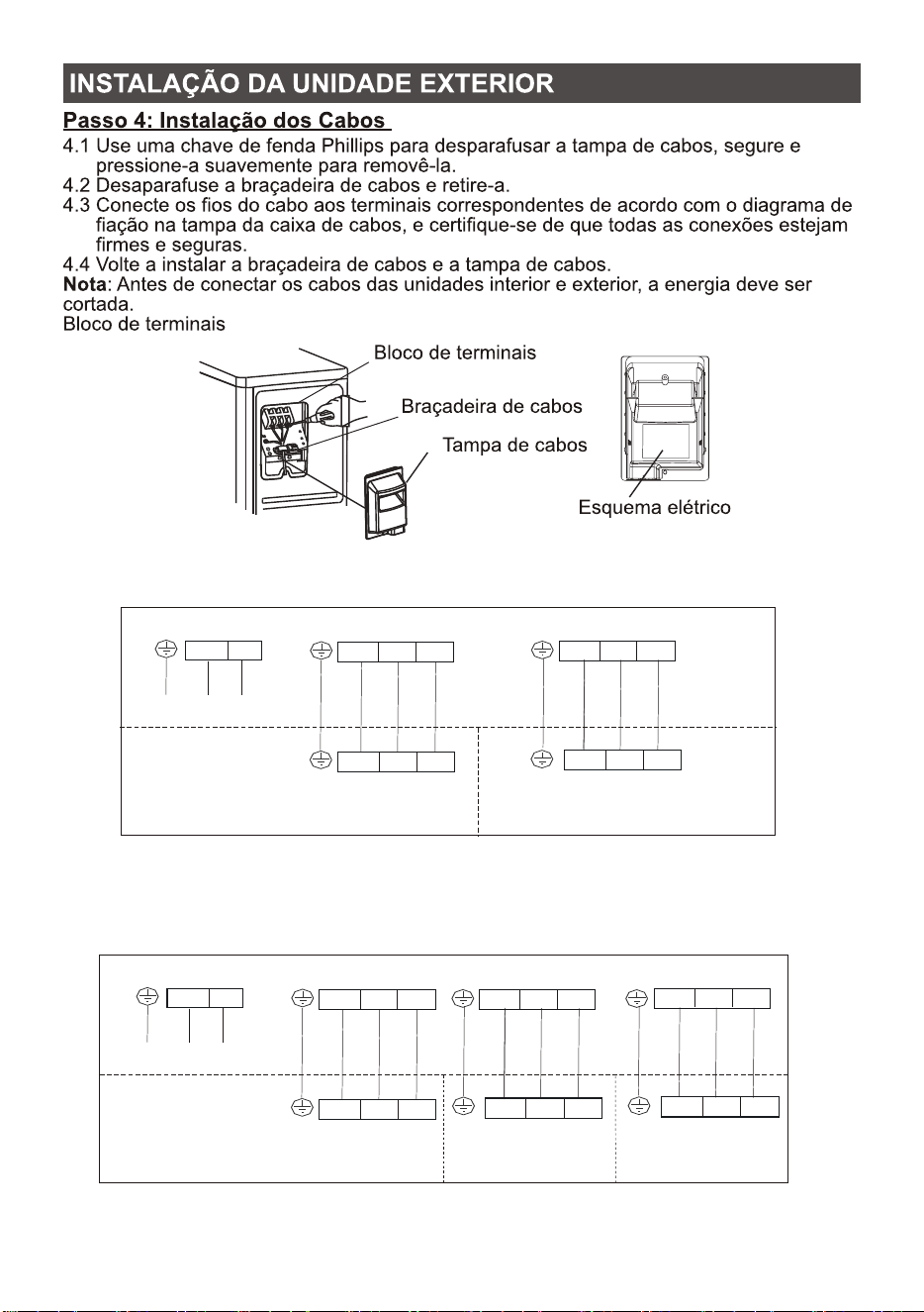
Step4: Install Wiring
Terminal block
Cable clamp
Wiring cover
Wiring diagram
OUTDOOR UNIT INSTALLATION
4.1 Use a phillips screwdriver to unscrew wiring cover, grasp and press it down gently to take it down.
4.2 Unscrew the cable clamp and take it down.
4.3 According to the wiring diagram pasted inside the wiring cover, connect the connecting
wires to the corresponding terminals, and ensure all connections are firmly and securely.
4.4 Reinstall the cable clamp and wiring cover.
Note: When connecting the wires of indoor and outdoor units, the power should be cut off.
POWER SUPPLY
LA
1A
NA
Outdoor
LB
1B
NB
L
1
N
N
L
1
N
N
Indoor A
Indoor B
N
L
POWER SUPPLY
LA
1A
NA
Outdoor
LB
1B
NB
LC
1C
NC
L
1
N
N
L
1
N
N
L
1
N
N
Indoor A
Indoor B
Indoor C
N
L
For dual system
For triple system
27
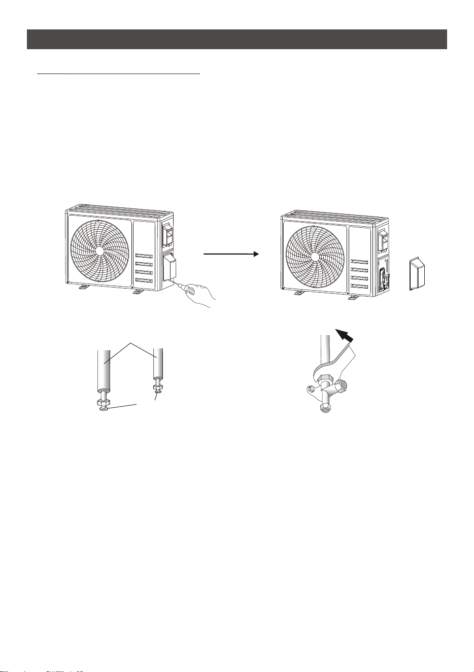
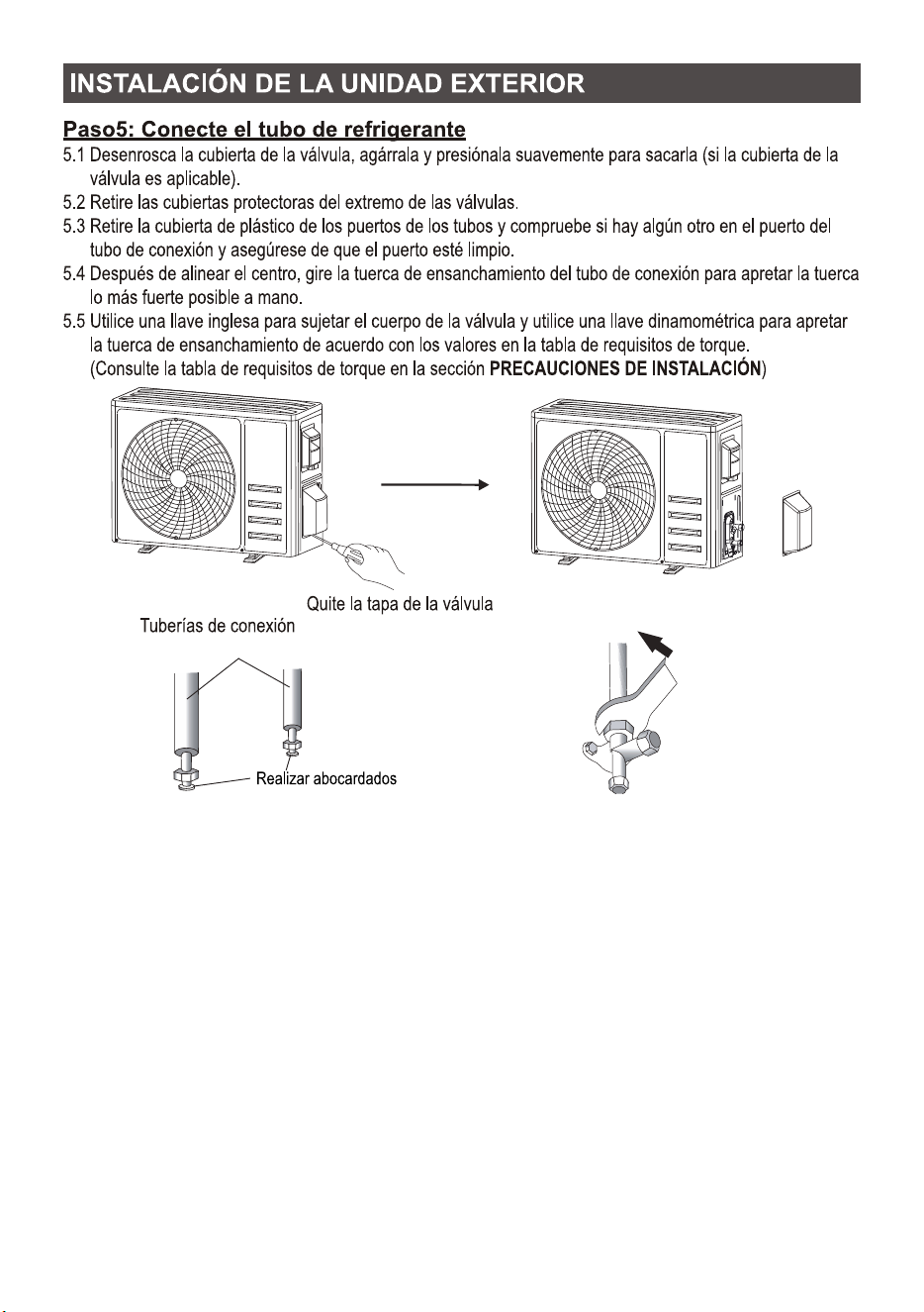
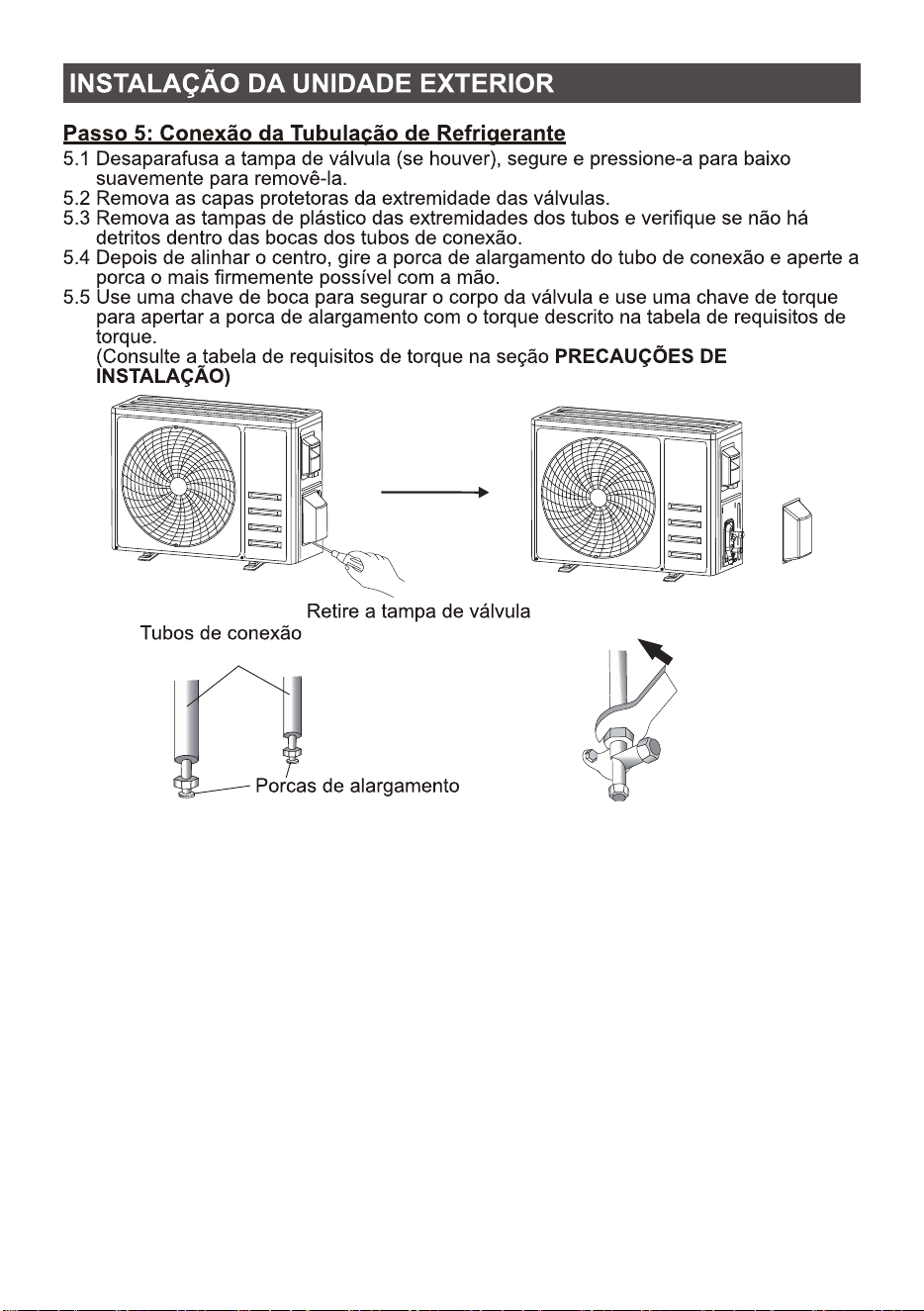
Step5:
Connecting Refrigerant Pipe
connection pipes
flare nuts
Take down the valve cover
OUTDOOR UNIT INSTALLATION
5.1 Unscrews the valve cover, grasp and press it down gently to take it down(if the valve cover is
applicable).
5.2 Remove the protective caps from the end of valves.
5.3 heck whether there is any sundry on the port of
the connecting pipe and make ensure the port is clean.
5.4 After align the center, rotate the flare nut of the connecting pipe to tighten the nut as tightly as
possible by hand.
5.5 Use a spanner hold the body of the valve and use a torque wrench to tighten the flare nut
according to the torque values in the torque requirements table.
(Refer to the torque requirements table on section INSTALLATION PRECAUTIONS)
Take off the plastic cover in the pipe ports and c
28
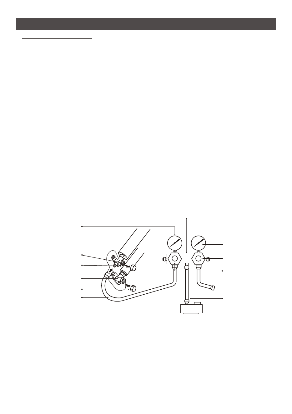
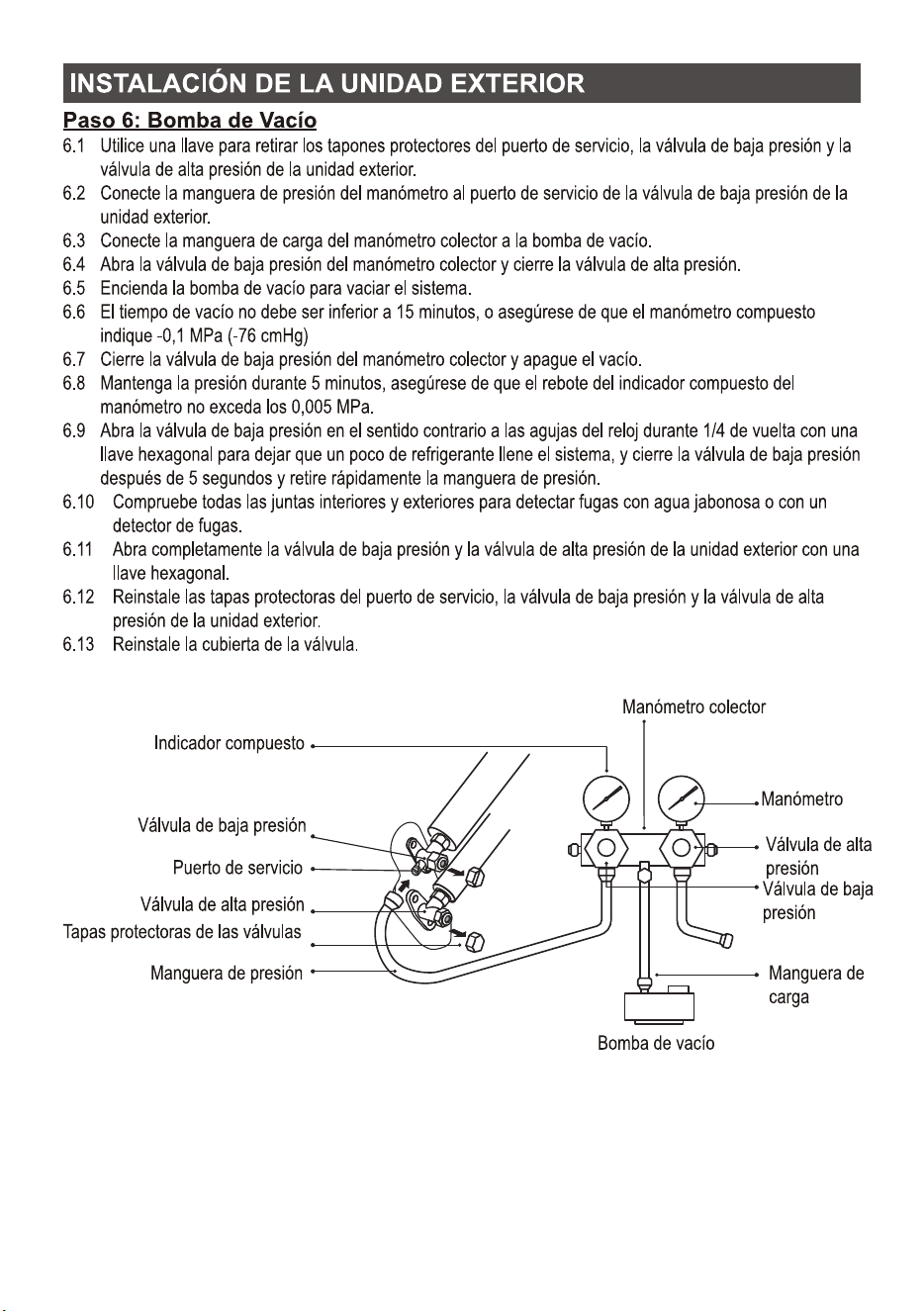
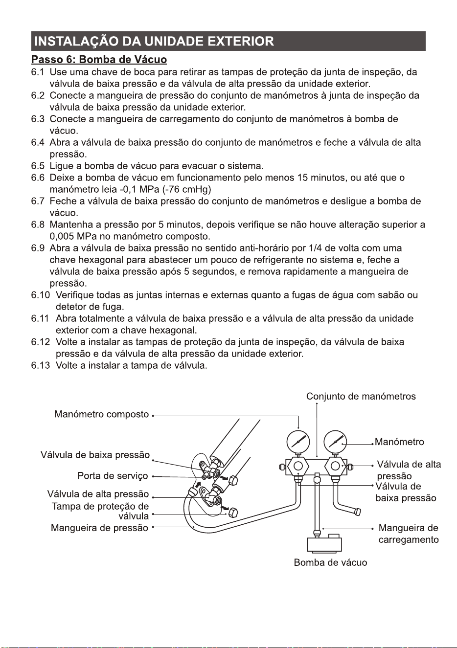
Step6: Vacuum Pumping
compound gauge
Low pressure valve
Valve protective caps
Pressure hose
Pressure gauge
High pressure valve
Charge hose
High pressure valve
Low pressure valve
Vacuum pump
Service port
Manifold gauge
OUTDOOR UNIT INSTALLATION
6.1 Use a spanner to take down the protective caps from the service port, low pressure valve and
high pressure valve of the outdoor unit.
6.2 Connect the pressure hose of manifold gauge to the service port on the outdoor unit low
pressure valve.
6.3 Connect the charge hose from the manifold gauge to the vacuum pump.
6.4 Open the low pressure valve of the manifold gauge and close the high pressure valve.
6.5
he vacuum time should not be less than 15 minutes, or make sure the compound gauge
indicates -0.1 MPa (-76 cmHg)
6.7 Close the low pressure valve of the manifold gauge and turn off the vacuum.
6.8 Hold the pressure for 5 minutes, make sure that the rebound of compound gauge pointer does
not exceed 0.005 MPa.
6.9 Open the low pressure valve counterclockwise for 1/4 turn with hexagonal wrench to let a little
refrigerant fill in the system, and close the low pressure valve after 5 seconds and quickly remove
the pressure hose.
6.10 Check all indoor and outdoor joints for leakage with soapy water or leak detector.
6.11 Fully open the low pressure valve and high pressure valve of the outdoor unit with hexagonal
wrench.
6.12 Reinstall the protective caps of the service port, low pressure valve and high pressure valve of
the outdoor unit.
6.13 Reinstall the valve cover.
Turn on the vacuum pump to vacuum the system.
6.6 T
29
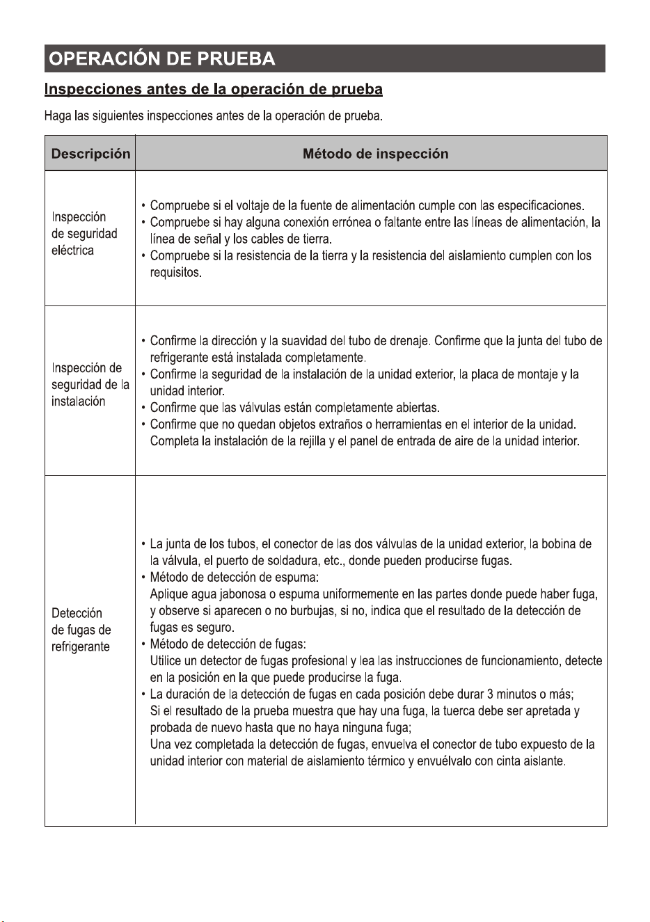
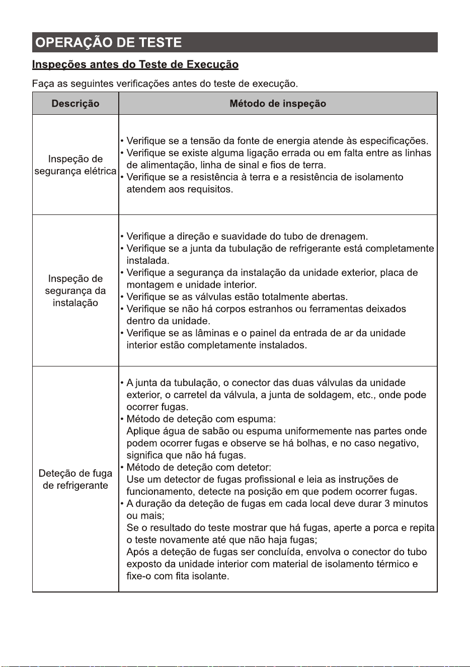
Electrical
safety inspection
Check whether the power supply voltage complies with specification.
Check whether there is any wrong or missing connection between the
power lines, signal line and earth wires.
Check whether the earth resistance and insulation resistance comply with
requirements.
Installation
safety inspection
Confirm the direction and smoothness of drainage pipe.
Confirm that the joint of refrigerant pipe is installed completely.
Confirm the safety of outdoor unit, mounting plate and indoor unit
installation.
Confirm that the valves are fully open.
Confirm that there are no foreign objects or tools left inside the unit.
Complete installation of indoor unit air inlet grille and panel.
Refrigerant
leakage detection
The piping joint, the connector of the two valves of the outdoor unit, the
valve spool, the welding port, etc., where leakage may occur.
Foam detection method:
Apply soapy water or foam evenly on the parts where leakage may occur,
and observe whether bubbles appear or not, if not, it indicates that the
leakage detection result is safe.
Leak detector method:
Use a professional leak detector and read the instruction of operation,
detect at the position where leakage may occur.
The duration of leak detection for each position should last for 3 minutes
or more;
If the test result shows that there is leakage, the nut should be tightened
and tested again until there is no leakage;
After the leak detection is completed, wrap the exposed pip connector of
indoor unit with thermal insulation material and wrap with insulation
tape.
TEST OPERATION
Do the following checks before test run.
Inspections Before Test Run
Description
Inspection method
30

TEST OPERATION
Test Run Instruction
1. Turn on the power supply.
2. Press the ON/OFF button on the remote controller to turn on the air conditioner.
3. Press the Mode button to switch the mode COOL and HEAT.
In each mode set as below:
COOL-Set the lowest temperature
HEAT-Set the highest temperature
4. Run about 8 minutes in each mode and check all functions are properly run and respond the
remote controller. Functions check as recommended:
4.1 If the outlet air temperature respond the cool and heat mode
4.2 If the water drains properly from the drainage hose
4.3 If the Louver and deflectors(optional) rotate properly
5. Observe the test run state of the air conditioner at least 30 minutes.
6. After the successfully test run, return the normal setting and press ON/OFF button on the remote
controller to turn off the unit.
7. Inform the user to read this manual carefully before use, and demonstrate to the user how to use
the air conditioner, the necessary knowledge for service and maintenance, and the reminder for
storage of accessories.
Note:
If the ambient temperature is excess the range refer to section OPERATION INSTRUCTIONS, and it
can not run COOL or HEAT mode, lift the front panel and refer to the emergency button operation
to run the COOL and HEAT mode.
31
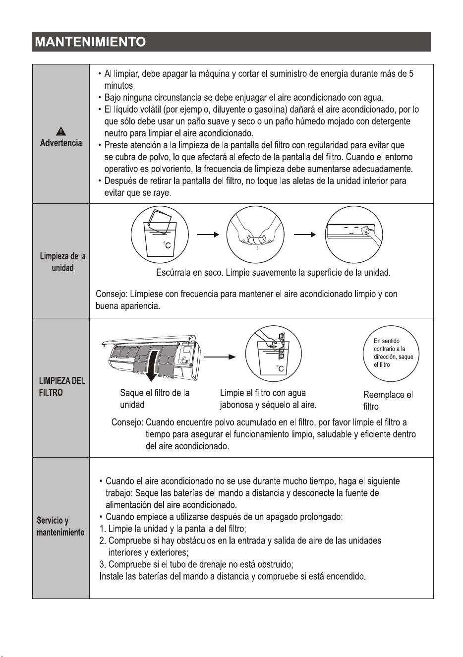
MAINTENANCE
Clean
the unit
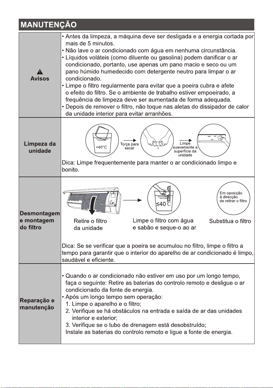
<40
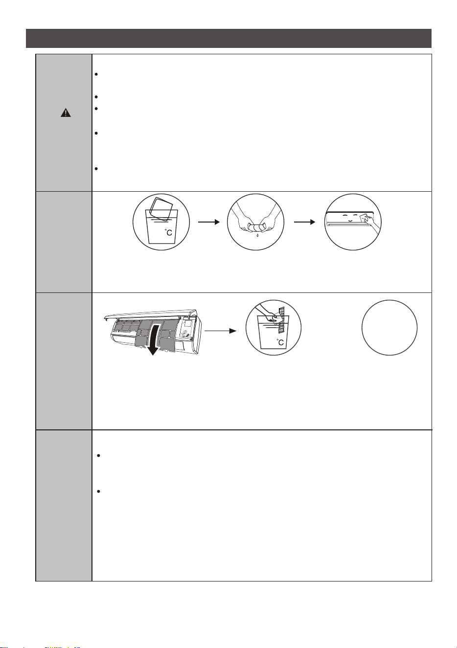
When cleaning, you must shut down the machine and cut off the power supply for more
than 5 minutes.
Under no circumstances should the air conditioner be flushed with water.
Volatile liquid (e.g. thinner or gasoline) will damage the air conditioner, so only use soft
dry cloth or wet cloth dipped with neutral detergent to clean the air conditioner.
Pay attention to cleaning the filter screen regularly to avoid dust covering which will
affect the filter screen effect. When the operating environment is dusty, the cleaning
frequency should be increased appropriately.
After removing the filter screen, do not touch the fins of the indoor unit to avoid scratching.
Tip: Wipe frequently to keep air conditioner clean and good appearance .
Wring it dry
Gentle wipe the unit surface
Warning
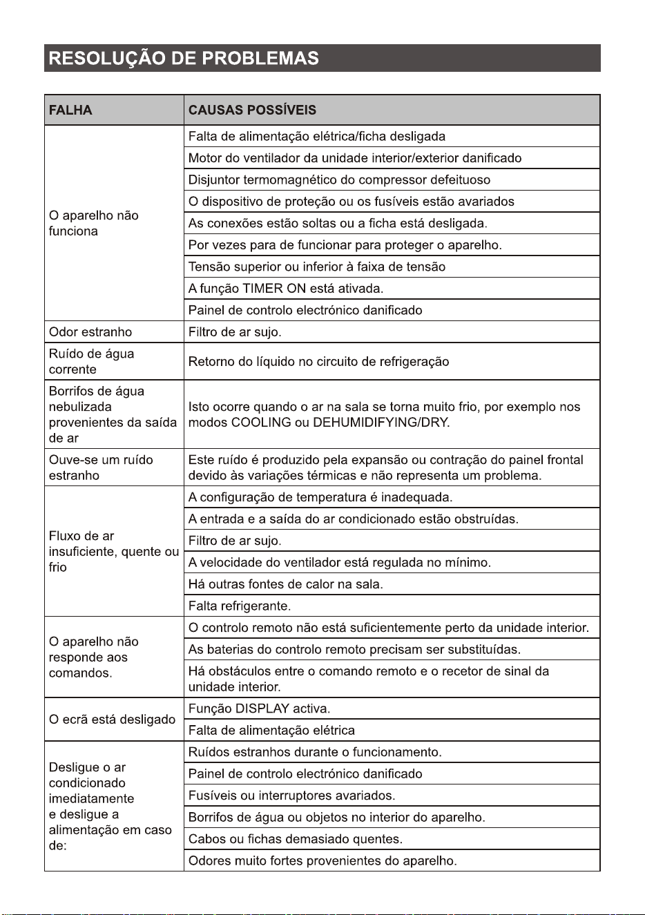
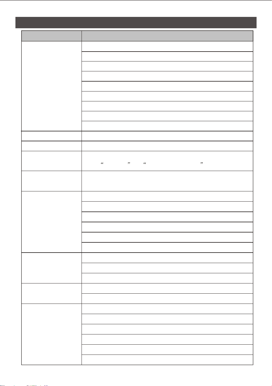
<40
Opposite to the
direction of taking
out the filter
Take out the filter
from the unit
Clean the filter with
soapy water and air dry it
Replace the filter
Tip: When you find accumulated dust in the filter, please clean the filter in time to
ensure the clean, healthy and efficient operation inside the air conditioner.
Clean
the filter
When the air conditioner is not in use for a long time, do the following work:
Take out the batteries of the remote controller and disconnect the power supply of
the air conditioner.
When starting to use after long-term shutdown:
1. Clean the unit and filter screen;
2. Check whether there are obstacles at the air inlet and outlet of indoor and outdoor
units;
3. Check whether the drain pipe is unobstructed;
Install the batteries of the remote controller and check whether the power is on.
Service and
maintenance
32
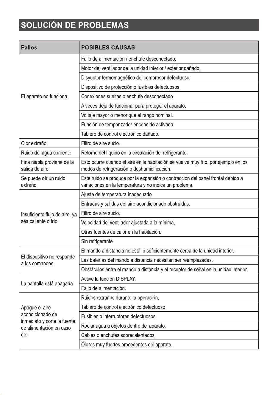
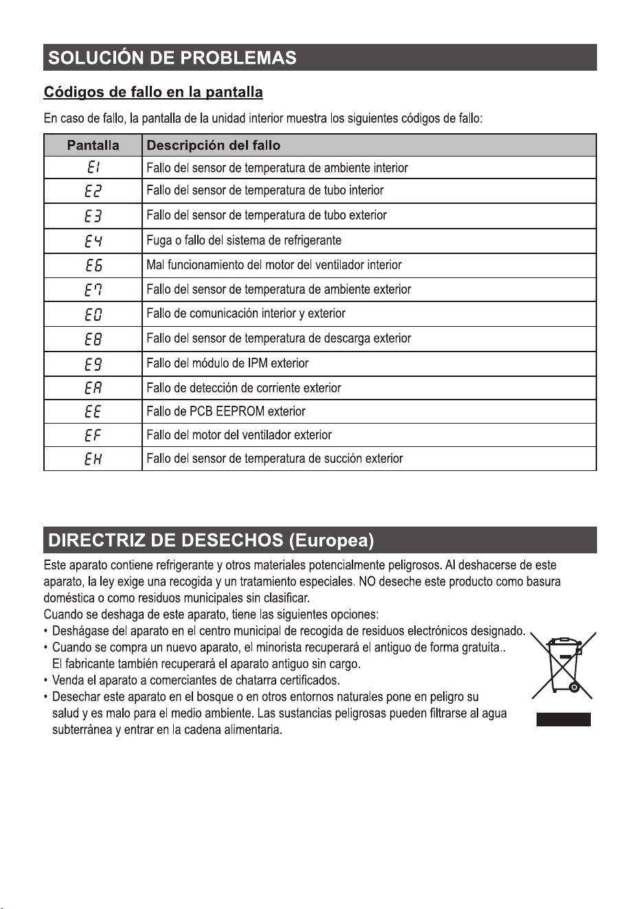
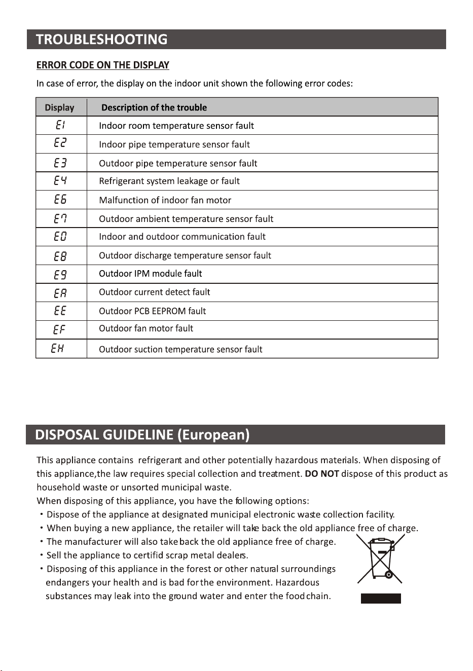
TROUBLESHOOTING
Strange odor
The appliance does
not operate
Noise of running water
A fine mist comes from
the air outlet
Insufficient airflow,
eitherhot or cold
The appliance does not
respond to commands
The display is off
Switch off the air
conditioner immediately
and cut off the power
supply in the event of:
A strange noise can be
heard
Power failure/plug pulled out.
Damaged indoor/outdoor unit fan motor.
Faulty compressor thermomagnetic circuit breaker.
Faulty protective device or fuses.
Loose connections or plug pulled out.
It sometimes stops operating to protect the appliance.
Voltage higher or lower than the voltage range.
Active TIMER-ON function.
Damaged electronic control board.
Dirty air filter.
Back flow of liquid in the refrigerant circulation.
This occurs when the air in the room becomes very cold, for example
in the COOLING or DEHUMIDIFYING/DRY modes.
This noise is made by the expansion or contraction of the front panel
due to variations in temperature and does not indicate a problem.
Unsuitable temperature setting.
Obstructed air conditioner intakes and outlets.
Dirty air filter.
Fan speed set at minimum.
Other sources of heat in the room.
No refrigerant.
Remote control is not close enough to indoor unit.
The batteries of remote control need to be replaced.
Obstacles between remote control and signal receiver in indoor unit.
Active DISPLAY function.
Power failure.
Strange noises during operation.
Faulty electronic control board.
Faulty fuses or switches.
Spraying water or objects inside the appliance.
Overheated cables or plugs.
Very strong smells coming from the appliance.
MALFUNCTION
POSSIBLE CAUSES
33
34

CONDICIONES DE LA GARANTÍA
en Aires Acondicionados
1. La Garantía tiene la duración de tres años en el aparato y siete en el compresor (en el compresor a partir de los tres años la
garantía incluye únicamente suministro de la pieza), a partir de la fecha de suministro y/o instalación. Nadie está autorizado a
modificar el plazo de garantía ni otorgar otras garantías verbales o por escrito.
2. La Garantía cubre todos los componentes del aparato y comprende la reparación y suministro gratuito de cualquier pieza por
defectos de fabricación. La sustitución o reparación de las piezas defectuosas no modifica la duración de la garantía.
3. En caso de sustitución del aparato por defecto de fabricación, por juzgar el fabricante o su representante legal que no tiene
reparación, la garantía del nuevo aparato continuará hasta el término de la Garantía del equipo original.
4. La Garantía no cubre los componentes averiados por transporte, por falta o error de mantenimiento, por suministro de
fluido eléctrico que no cumpla la normativa vigente, por manipulaciones efectuadas por operarios no autorizados o por causas
no imputables al fabricante. Se excluyen también de la Garantía las intervenciones originadas por defectos de la instalación.
5. La Garantía se valida si:
a) El aparato ha sido instalado en España o Portugal de acuerdo con las normas vigentes y con las
prescripciones del manual de instalación y usuario.
b) El aparato dispone de un mantenimiento preventivo por parte del Personal de Asistencia Técnica
autorizado, según las recomendaciones del manual de instalación y usuario.
c) El aparato ha sido instalado por instalador autorizado.
6. Se considera que la Garantía prescribe por:
a) Manipulación por parte de personal no autorizado legalmente para ello.
b) Instalación eléctrica o hidráulica no conforme con las normas vigentes o como se describe en el
manual de instalación y usuario.
c) Utilización de métodos diversos a los descritos en el manual de instalación y usuario o con fines
distintos a los que está destinado el aparato.
d) Imposibilidad del usuario de exhibir al personal autorizado la factura de compra y de instalación
de un instalador autorizado.
7. El importador responde ante la ley de los daños causados a personas o cosas por vicios de construcción en sus aparatos
siempre y cuando se cumplan las condiciones anteriormente expuestas. En cualquier caso, se excluyen los daños causados por
la suspensión del funcionamiento del aparato.
8. Cuando el aparato deba repararse en el taller del Servicio de Asistencia Técnica indicado por el importador, los riesgos del
transporte correspondiente serán a cargo del usuario en el caso de envío directo y a cargo del SAT en el caso de retirarlo del
domicilio del Usuario. En el caso de tratarse de un cliente sin cuenta abierta en el importador, antes de la reparación deberá
realizar un pago que cubra la reparación en caso de estar fuera de la garantía por uso indebido o por una mala instalación.
9. Quedan excluidos de la garantía, por no formar parte de la misma:
- La reposición de los materiales fungibles por funcionamiento como por ejemplo, a título enunciativo
y no limitativo, el gas refrigerante, el aceite del compresor, los filtros de aceite, etc.
- Los gastos extraordinarios ocasionados por el difícil acceso a la unidad (grúas, andamios, montajes
y desmontajes de estos dispositivos, permisos, recursos preventivos, etc.), siendo responsabilidad
exclusiva del titular de la instalación garantizar un acceso seguro y suficiente a la unidad/es instalada/s.
10. Las cuestiones que se suscriten como consecuencia de la aplicación o interpretación de esta garantía, deberán dirimirse
ante los tribunales de Justicia de Barcelona, con renuncia expresa a su Fuero Propio por parte del adquiriente del aparato
objeto de esta Garantía.
Servicio Técnico Oficial: 94 612 28 84
Horario de atención Lunes a Viernes de 8 h a 20 h y Sábado de 9 h a 13 h. Teléfono de contacto 94 612 28 84. Mail de contacto: [email protected] / [email protected]
Dirección de Servicio Técnico Oficial: SARETEKNIKA - Polo de Innovación Garaia, Edificio B - 20500 Arrasate - Guipuzkoa
ACCEDE A MAS INFORMACIÓN: Escaneando con la cámara de su teléfono móvil el siguiente código
QR accederá a nuestra web donde encontrará la información necesaria.
EN CASO DE AVERÍA: Puede contactar con nuestro departamento de Servicio Técnico:
Este equipo deberá ser instalado y configurado por un técnico cualificado de acuerdo a las normas establecidas por la normativa local
en materia de salud y seguridad, como el reglamento electrotécnico de baja tensión, el código técnico de edificación y los reglamentos
locales pertinentes.

CONDICIONES DE LA GARANTÍA
en Termos y Calentadores
Servicio Técnico Oficial: 94 612 28 84
Horario de atención Lunes a Viernes de 8 h a 20 h y Sábado de 9 h a 13 h. Teléfono de contacto 94 612 28 84. Mail de contacto: [email protected] / [email protected]
Dirección de Servicio Técnico Oficial: SARETEKNIKA - Polo de Innovación Garaia, Edificio B - 20500 Arrasate - Guipuzkoa
ACCEDE A MAS INFORMACIÓN: Escaneando con la cámara de su teléfono móvil el siguiente código
QR accederá a nuestra web donde encontrará la información necesaria.
EN CASO DE AVERÍA: Puede contactar con nuestro departamento de Servicio Técnico:
Este equipo deberá ser instalado y configurado por un técnico cualificado de acuerdo a las normas establecidas por la normativa local
en materia de salud y seguridad, como el reglamento electrotécnico de baja tensión, el código técnico de edificación y los reglamentos
locales pertinentes.
Imprescindible la presentación de la factura de compra acompañada del presente certificado de garantía.
Riesgos Cubiertos.
Este aparato está garantizado contra cualquier defecto de funcionamiento, siempre que se destine a uso doméstico,
procediéndose a su reparación dentro del plazo de garantía y sólo por la red de SAT autorizados.
Nuestros electrodomésticos Corberó cuentan con la garantía legal del fabricante que cubre cualquier avería o defecto durante
36 meses, desde su fecha de 1 de enero del 2022. En caso de que fuera necesario, nosotros nos ocupamos de cualquier posible
incidencia siempre que se deba a un componente defectuoso o fallo de fabricación.
Excepciones de garantía.
• Que la fecha del certificado no coincida con la fecha de venta de la factura original.
• Averías producidas por golpe, por caída o cualquier otra causa de fuerza mayor.
• Si el aparato ha sido manipulado por personal no autorizado.
• Las averías producidas o derivadas como consecuencia de un uso inadecuado, por defectos de instalación,
por introducir modificaciones en el aparato que alteren su funcionamiento.
• Puestas en marcha, mantenimiento, limpiezas, componentes sujetos a desgaste, lámparas, piezas estéticas,
oxidaciones, plásticos, gomas, carcasas y cristales.
Garantía termos eléctricos.
Garantía de 3 años incluyendo los costes de desplazamiento y mano de obra que correspondan de la reparación del producto,
debiendo tener un mantenimiento una vez cada 12 meses. Especialmente si Ud. ha instalado un aparato a gas, tenga presente
como titular de la instalación, la obligatoriedad de realizar una revisión completa de los equipos, (según Real Decreto 238 /
2013, del 5 abril. RITE. IT3.
Este equipo deberá ser instalado y configurado por un técnico cualificado de acuerdo a las normas establecidas por la
normativa local en materia de salud y seguridad, como el reglamento electrotécnico de baja tensión, el código técnico de
edificación y los reglamentos locales pertinentes.
Lo termos eléctricos y calderas que incluyen depósitos acumuladores de agua caliente, para que se aplique la prestación de
la Garantía, es obligatorio que el ánodo de magnesio esté operativo y que realice la función de protección adecuadamente.
Para ello es recomendable que el ánodo se revise bianualmente por el Servicio Oficial y sea renovado cuando fuera necesario.
Periodicidad que deberá ser anual en aquellas zonas con aguas críticas (contenido de CaCO3 superiores a 200mg/L, es decir a
partir de 20ºfH de dureza).
Depósitos sin el correcto estado del ánodo de protección, no tienen la cobertura de la garantía. Independientemente del tipo
de depósito o producto, todas las válvulas de sobrepresión de calefacción o a.c.s., deberán ser canalizadas para evitar daños
en Ia vivienda por descargas de agua. La garantía del producto no asume los daños causados por Ia no canalización del agua
derramada por esta válvula.
WARRANTY CONDITIONS
in Air Conditioners
1. The Warranty lasts three years on the device and seven on the compressor (for the compressor after three years the warran-
ty includes only the supply of the part), starting from the date of supply and/or installation. No one is authorized to modify the
warranty period or grant other verbal or written guarantees.
2. The Guarantee covers all components of the device and includes the free repair and supply of any part due to manufacturing
defects. The replacement or repair of defective parts does not modify the duration of the warranty.
3.
In the event of replacement of the device due to a manufacturing defect, in the opinion of the manufacturer or its legal repre-
sentative that it cannot be repaired, the warranty of the new device will continue until the end of the original equipment warranty.
4. The Warranty does not cover components damaged due to transportation, lack or error in maintenance, supply of
electrical fluid that does not comply with current regulations, due to manipulations carried out by unauthorized operators or for
reasons not attributable to the manufacturer. Interventions caused by installation defects are also excluded from the Guarantee.
5. The Guarantee is validated if:
a) The device has been installed in Spain or Portugal in accordance with current regulations and with
the instructions of the installation and user manual.
b) The device has preventive maintenance by the Technical Assistance Personnel authorized, according
to the recommendations of the installation and user manual.
c) The device has been installed by an authorized installer.
6. It is considered that the Guarantee expires:
a) Tampering by personnel not legally authorized to do so.
b) Electrical or hydraulic installation not in compliance with current standards or as described in the
installation and user manual.
c) Use of methods other than those described in the installation and user manual or for purposes
other than those for which the device is intended.
d) Inability of the user to show the purchase and installation invoice to authorized personnel from
an authorized installer.
7. The importer is liable before the law for damages caused to people or things due to construction defects in their devices
as long as the conditions set out above are met. In any case, damage caused by the suspension of operation of the device is
excluded.
8. When the device must be repaired in the Technical Assistance Service workshop indicated by the importer, the correspon-
ding transportation risks will be borne by the user in the case of direct shipping and by the SAT in the case of removal from
the User’s home. In the case of a customer without an open account with the importer, before the repair you must make a
payment to cover the repair if it is outside the warranty due to improper use or poor installation.
9. They are excluded from the guarantee, as they are not part of it.:
- The replacement of consumable materials due to operation, such as, but not limited to, and not
limited to, refrigerant gas, compressor oil, oil filters, etc.
- Extraordinary expenses caused by difficult access to the unit (cranes, scaffolding, assembly and
disassembly of these devices, permits, preventive resources, etc.), being the responsibility exclusive
of the owner of the installation to guarantee safe and sufficient access to the installed unit/s.
10. The issues that arise as a consequence of the application or interpretation of this guarantee must be resolved before the
Courts of Justice of Barcelona, with express waiver of its own jurisdiction by the purchaser of the device that is the subject of
this Guarantee.
Official technical service: 94 612 28 84
Opening hours Monday to Friday from 8 a.m. to 8 p.m. and Saturday from 9 a.m. to 1 p.m. Contact telephone number 94 612 28 84. Contact email: [email protected] / atencionalcliente@sareteknika.es
Official Technical Service Directorate: SARETEKNIKA - Polo de Innovación Garaia, Edificio B - 20500 Arrasate - Guipuzkoa
ACCESS MORE INFORMATION: By scanning the following QR code with your mobile phone camera
you will access our website where you will find the necessary information.
IN CASE OF BREAKDOWN: You can contact our Technical Service department:
This equipment must be installed and configured by a qualified technician in accordance with the standards established by local health
and safety regulations, such as low voltage electrotechnical regulations, technical building code and relevant local regulations.
WARRANTY CONDITIONS
Electrical and Gas water heaters
It is essential to present the purchase invoice accompanied by this warranty certificate.
Covered Risks.
This appliance is guaranteed against any defect in operation, provided it is intended for domestic use,
proceeding to repair it within the warranty period and only through the authorized SAT network.
Our Corberó appliances have the manufacturer’s legal warranty that covers any breakdown or defect for 36 months,
from its date of January 1, 2022. If necessary, we will take care of any possible incident as long as it is due to a de-
fective component or manufacturing fault.
Warranty Exceptions.
• That the date of the certificate does not coincide with the sale date of the original invoice.
• Breakdowns caused by impact, fall or any other cause of force majeure.
• If the device has been manipulated by unauthorized personnel.
• Breakdowns produced or derived as a result of improper use, installation defects,
for introducing modifications to the device that alter its operation.
• Start-up, maintenance, cleaning, components subject to wear, lamps, aesthetic parts,
oxidations, plastics, rubber, casings and glass.
Electric water heater warranty.
3-year warranty including travel and labor costs corresponding to the repair of the product, and must have maintenance once
every 12 months. Especially if you have installed a gas appliance, keep in mind as the owner of the installation, the obligation
to carry out a complete review of the equipment (according to Royal Decree 238 / 2013, of April 5. RITE. IT3.
This equipment must be installed and configured by a qualified technician in accordance with the standards established by the
local health and safety regulations, such as the low voltage electrotechnical regulation, the technical code of
building and relevant local regulations.
For electric water heaters and boilers that include hot water storage tanks, for the Guarantee benefit to be applied, it is man-
datory that the magnesium anode is operational and that it performs the protection function adequately. To this end, it is re-
commended that the anode be checked biannually by the Official Service and renewed when necessary. Periodicity that must
be annual in those areas with critical waters (CaCO3 content greater than 200mg/L, that is, from 20ºfH hardness).
Tanks without the correct state of the protective anode do not have warranty coverage. Regardless of the type of tank or
product, all heating or DHW overpressure valves must be channeled to avoid damage to the home due to water discharges.
The product warranty does not cover damage caused by the failure to channel the water spilled through this valve.
Official technical service: 94 612 28 84
Opening hours Monday to Friday from 8 a.m. to 8 p.m. and Saturday from 9 a.m. to 1 p.m. Contact telephone number 94 612 28 84. Contact email: [email protected] / atencionalcliente@sareteknika.es
Official Technical Service Directorate: SARETEKNIKA - Polo de Innovación Garaia, Edificio B - 20500 Arrasate - Guipuzkoa
ACCESS MORE INFORMATION: By scanning the following QR code with your mobile phone camera
you will access our website where you will find the necessary information.
IN CASE OF BREAKDOWN: You can contact our Technical Service department:
This equipment must be installed and configured by a qualified technician in accordance with the standards established by local health
and safety regulations, such as low voltage electrotechnical regulations, technical building code and relevant local regulations.
CONDIÇÕES DE GARANTIA
em Ar Condicionado
1. A Garantia é de três anos para o aparelho e sete para o compressor (para o compressor após três anos a garantia inclui
apenas o fornecimento da peça), a partir da data de fornecimento e/ou instalação. Ninguém está autorizado a modificar o
período de garantia ou conceder outras garantias verbais ou escritas.
2. A Garantia cobre todos os componentes do dispositivo e inclui a reparação e fornecimento gratuito de qualquer peça devido
a defeitos de fabrico. A substituição ou reparação de peças defeituosas não altera a duração da garantia.
3. Em caso de substituição do aparelho por defeito de fabricação, na opinião do fabricante ou de seu representante legal de que
o mesmo não pode ser reparado, a garantia do novo aparelho continuará até o término da garantia original do equipamento.
4. A Garantia não cobre componentes danificados por transporte, falta ou erro de manutenção, fornecimento de
fluido elétrico que não esteja em conformidade com as normas vigentes, devido a manipulações realizadas por operadores
não autorizados ou por motivos não imputáveis ao fabricante. As intervenções causadas por defeitos de instalação também
estão excluídas da Garantia.
5. A Garantia é validada se:
a) O dispositivo foi instalado em Espanha ou Portugal de acordo com as normas vigentes e com as
instruções do manual de instalação e do usuário.
b) O aparelho conta com manutenção preventiva pelo Pessoal de Assistência Técnica
autorizado, conforme recomendações do manual de instalação e do usuário.
c) O dispositivo foi instalado por um instalador autorizado.
6. Considera-se que a Garantia expira:
a) Adulteração por pessoal não autorizado legalmente para fazê-lo.
b) Instalação elétrica ou hidráulica não conforme com as normas vigentes ou conforme descrito no
instalação e manual do usuário.
c) Uso de métodos diferentes daqueles descritos no manual de instalação e do usuário ou para fins
diferentes daqueles para os quais o dispositivo se destina.
d) Incapacidade do usuário de mostrar a fatura de compra e instalação ao pessoal autorizado
de um instalador autorizado.
7. O importador é responsável perante a lei pelos danos causados a pessoas ou coisas devido a defeitos de construção nos
seus dispositivos, desde que cumpridas as condições acima expostas. Em qualquer caso, estão excluídos os danos causados
pela suspensão do funcionamento do dispositivo.
8. Quando o aparelho precisar ser reparado na oficina do Serviço de Assistência Técnica indicada pelo importador, os corres-
pondentes riscos de transporte serão arcados pelo usuário no caso de envio direto e pelo SAT no caso de retirada do domicílio
do Usuário. No caso de cliente sem conta aberta no importador, antes do reparo deverá efetuar um pagamento para cobrir o
reparo caso este esteja fora da garantia por uso indevido ou má instalação.
9. Estão excluídos da garantia, pois não fazem parte dela.:
- A substituição de materiais consumíveis devido à operação, tais como, mas não se limitando a,
e não limitado a gás refrigerante, óleo de compressor, filtros de óleo, etc.
- Despesas extraordinárias causadas pela dificuldade de acesso à unidade (guindastes, andaimes, montagem
e desmontagem destes dispositivos, licenças, recursos preventivos, etc.), sendo de responsabilidade exclusivo
do proprietário da instalação para garantir acesso seguro e suficiente à(s) unidade(s) instalada(s).
10. As questões que surjam como consequência da aplicação ou interpretação desta garantia deverão ser resolvidas perante
os Tribunais de Justiça de Barcelona, com renúncia expressa à sua própria jurisdição por parte do comprador do dispositivo
objeto desta Garantia.
Serviço técnico oficial: (00 351) 707 01 01 42
Horário de funcionamento de segunda a sexta das 9h às 16h. Telefone de contato (00 351) 707 01 01 42. Email de contato: [email protected] / atencionalcliente@sareteknika.es
Diretoria Oficial de Serviço Técnico: SARETEKNIKA - Polo de Innovación Garaia, Edificio B - 20500 Arrasate - Guipuzkoa
ACESSE MAIS INFORMAÇÕES: Ao digitalizar o seguinte código QR com a câmera do seu celular
você acessará nosso site onde encontrará as informações necessárias.
EM CASO DE AVARIA:
Você pode entrar em contato com nosso departamento de Assistência Técnica:
Este equipamento deve ser instalado e configurado por um técnico qualificado de acordo com os padrões estabelecidos pelas regu-
lamentações locais de saúde e segurança, como regulamentações eletrotécnicas de baixa tensão, código técnico de construção e
regulamentações locais relevantes.

CONDIÇÕES DE GARANTIA
em garrafas térmicas e aquecedores
Serviço técnico oficial: (00 351) 707 01 01 42
ACESSE MAIS INFORMAÇÕES: Ao digitalizar o seguinte código QR com a câmera do seu celular
você acessará nosso site onde encontrará as informações necessárias.
EM CASO DE AVARIA:
Você pode entrar em contato com nosso departamento de Assistência Técnica:
Este equipamento deve ser instalado e configurado por um técnico qualificado de acordo com os padrões estabelecidos pelas regu-
lamentações locais de saúde e segurança, como regulamentações eletrotécnicas de baixa tensão, código técnico de construção e
regulamentações locais relevantes.
É imprescindível a apresentação da nota fiscal de compra acompanhada deste certificado de garantia.
Riscos Cobertos.
Este aparelho está garantido contra qualquer defeito de funcionamento, desde que se destine a uso doméstico,
procedendo à sua reparação dentro do período de garantia e apenas através da rede SAT autorizada.
Os nossos aparelhos Corberó contam com garantia legal do fabricante que cobre qualquer avaria ou defeito durante
36 meses, a partir da data de 1º de janeiro de 2022. Se necessário, cuidaremos de qualquer possível incidente, desde
que seja devido a defeito de componente ou fabricação. falta.
Exceções de garantia.
• Que a data do certificado não coincide com a data de venda da fatura original.
• Avarias causadas por impacto, queda ou qualquer outra causa de força maior.
• Se o dispositivo tiver sido manipulado por pessoal não autorizado.
• Avarias produzidas ou derivadas de uso indevido, defeitos de instalação, por
introduzir modificações no dispositivo que alterem seu funcionamento.
• Arranque, manutenção, limpeza, componentes sujeitos a desgaste, lâmpadas, peças estéticas,
oxidações, plásticos, borracha, invólucros e vidro.
Garantia do aquecedor elétrico de água.
Garantia de 3 anos incluindo despesas de viagem e mão de obra correspondentes ao reparo do produto, devendo ter ma-
nutenção uma vez a cada 12 meses. Principalmente se instalou um aparelho a gás, tenha em atenção, como proprietário da
instalação, a obrigação de efectuar uma revisão completa do equipamento (de acordo com o Real Decreto 238/2013, de 5 de
abril. RITE. IT3.
Este equipamento deve ser instalado e configurado por técnico qualificado de acordo com as normas estabelecidas pela
regulamentos locais de saúde e segurança, como o regulamento eletrotécnico de baixa tensão, o código técnico de
construção e regulamentos locais relevantes.
Nos termoacumuladores elétricos e nas caldeiras que incluam reservatórios de água quente, para que o benefício da Garantia
possa ser aplicado é obrigatório que o ânodo de magnésio esteja operacional e desempenhe adequadamente a função de
proteção. Para tanto, recomenda-se que o ânodo seja verificado semestralmente pelo Serviço Oficial e substituído quando
necessário. Periodicidade que deve ser anual nas áreas com águas críticas (teor de CaCO3 superior a 200mg/L, ou seja, a partir
de dureza de 20ºfH).
Os tanques sem o estado correto do ânodo protetor não têm cobertura de garantia. Independentemente do tipo de depósito
ou produto, todas as válvulas de sobrepressão de aquecimento ou AQS devem ser canalizadas para evitar danos na habitação
devido a descargas de água. A garantia do produto não cobre danos causados pela não canalização da água derramada por
esta válvula.
Horário de funcionamento de segunda a sexta das 9h às 16h. Telefone de contato (00 351) 707 01 01 42. Email de contato: [email protected] / atencionalcliente@sareteknika.es
Diretoria Oficial de Serviço Técnico: SARETEKNIKA - Polo de Innovación Garaia, Edificio B - 20500 Arrasate - Guipuzkoa