
OWNER’S MANUAL
INSTALLATION, OPERATION & PARTS
SAVE THIS INSTRUCTION MANUAL
IS210T90
Rev. D
MODEL S210T, S210T93 PRO SERIES
HIGH-RATE SAND FILTRATION SYSTEM
Basic safety precautions should always be followed, including the following: Failure to follow instructions can cause severe
injury and/or death.
This is the safety-alert symbol. When you see this symbol on your equipment or in this manual, look for one of the
following signal words and be alert to the potential for personal injury.
WARNING warns about hazards that could cause serious personal injury, death or major property damage and if
ignored presents a potential hazard.
CAUTION warns about hazards that will or can cause minor or moderate personal injury and/or property damage
and if ignored presents a potential hazard. It can also make consumers aware of actions that are unpredictable and unsafe..
The NOTICE label indicates special instructions that are important but not related to hazards.
HAYWARD POOL PRODUCTS
POMONA, CA CLEMMONS, NC NASHVILLE, TN
WWW.HAYWARDPOOL.COM
Use only High Rate Sand No. 20 Silica Sand (.45mm - .55mm)
Page 2 of 8 MODEL S210T, S210T90 IS210T90 Rev D
WWW.HAYWARDPOOL.COM USE ONLY HAYWARD GENUINE REPLACEMENT PARTS
WARNING READ, UNDERSTAND, AND FOLLOW ALL SAFETY AND OPERATION
INSTRUCTIONS. FAILURE TO FOLLOW SAFETY AND OPERATION INSTRUCTIONS CAN RESULT IN
SEVERE PERSONAL INJURY OR DEATH.
WARNING – SUCTION ENTRAPMENT HAZARD.
Suction in suction outlets and/or suction outlet covers that are, damaged, broken, cracked, missing, or
unsecured can cause severe injury and/or death due to the following entrapment hazards:
Hair Entrapment- Hair can become entangled in suction outlet cover.
Limb Entrapment- A limb inserted into an opening of a suction outlet sump or suction outlet cover that is
damaged, broken, cracked, missing, or not securely attached can result in a mechanical bind or swelling of the
limb.
Body Suction Entrapment- A negative pressure applied to a large portion of the body or limbs can result in an
entrapment.
Evisceration/ Disembowelment Entrapment- A negative pressure applied directly to the intestines through an
unprotected suction outlet sump or suction outlet cover that is, damaged, broken, cracked, missing, or
unsecured can result in evisceration/ disembowelment entrapment.
Mechanical Entrapment- There is potential for jewelry, swimsuit, hair decorations, finger, toe or knuckle to be
caught in an opening of a suction outlet cover resulting in mechanical entrapment.
WARNING TO REDUCE THE RISK OF ENTRAPMENT HAZARDS:
A minimum of two functioning suction outlets per pump must be installed. Suction outlets in the same
plane (i.e. floor or wall), must be installed a minimum of three feet (3’) [1 meter] apart, as measured
from near point to near point.
Dual suction fittings shall be placed in such locations and distances to avoid “dual blockage” by a user.
Dual suction fittings shall not be located on seating areas or on the backrest for such seating areas.
The flow system shall be designed to comply with the flow rating of ASME/ANSI A112.19.8-2007 and
ANSI/APSP-7 2006.
Never use Pool or Spa if any suction outlet component (cover/grate) is damaged, broken, cracked, missing,
or not securely attached.
Replace damaged, broken, cracked, missing, or not securely attached suction outlet components
immediately.
Installation of a vacuum release system, which relieves entrapping suction, is recommended.
Failure to remove pressure test plugs and/or plugs used in winterization of the pool/spa from the suction
outlets can result in an increased potential for suction entrapment.
Failure to keep suction outlet components clear of debris, such as leaves, dirt, hair, paper and other
material can result in an increased potential for suction entrapment.
Suction outlet covers and grates have a finite life. They should be inspected frequently and replaced
periodically.
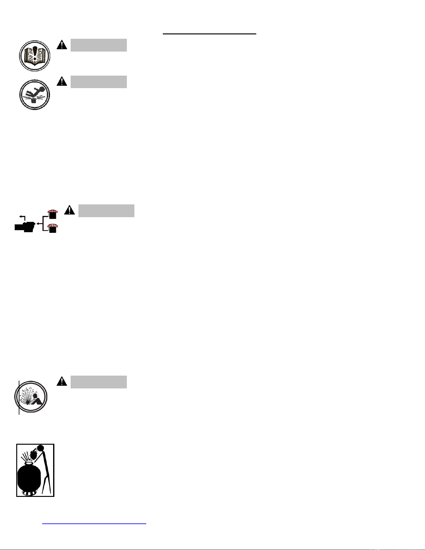
WARNING COMPONENT SEPARATION HAZARD
Pool and spa water circulation systems operate under hazardous pressure during start up, normal
operation, and possibly after pump shut off. Pressure in system can cause violent separation of the
pump and/or filter components if safety and operation instructions are not followed. Component
separation can result in severe personal injury or death.
Do not operate water circulation system if a system component is assembled improperly, damaged,
missing, or not a genuine Hayward component.
Before performing maintenance on the water circulation system, verify all system and pump controls are in
OFF position and filter manual air relief valve is in the OPEN position.
Before starting the system pump, verify that all system valves are set in a position to allow water from the
filter to return back to the pool.
Before starting the system pump, the manual air relief valve must be in the OPEN position.
When starting system pump, stand at least 10 feet away from filter.
Return to filter to close manual air relief valve only when a steady stream of water (Not air or air and water
mix) is discharged from the manual air relief valve.
Do not change filter control valve position while system pump is running.
Page 3 of 8 MODEL S210T, S210T90 IS210T90 Rev D
WWW.HAYWARDPOOL.COM USE ONLY HAYWARD GENUINE REPLACEMENT PARTS
WARNING EXCESS PRESSURE HAZARD
Pressure testing of the pump and filter system in excess of the 30 PSI can cause violent separation of
the components. Component separation can result in severe personal injury or death.
WARNING
ELECTROCUTION HAZARD
High Voltage electricity is present in the pool and spa equipment. High voltage electricity can cause shock and
electrocution. Shock and electrocution can result in severe personal injury or death.
All electrical wiring MUST be in conformance with applicable local codes, regulations and the
National Electrical Code (NEC)
Before performing any service or maintenance on electrical equipment turn off all electrical power.
Contact a licensed electrician or building inspector for information on local electrical codes for
bonding requirements.
Verify water discharge from the filter manual air relief valve is directed away from electrical
devices.
To reduce risk of injury, do not permit children to use or climb on this product. Closely supervise
children at all times. The ANSI/NSPI-4 Standard (above-ground and on-ground pools) advises that components such as
the filtration system, pumps, and heaters be positioned to prevent their being used as a means of access to the pool by
young children.
WARNING – Failure to remove pressure test plugs and/or plugs used in winterization of the pool/spa
from the suction outlets can result in an increase potential for suction entrapment as described above.
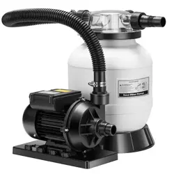
Your Hayward Pro Series high-rate sand filter is a high performance, totally corrosion-proof filter that blends superior flow
characteristics and features with ease of operation. It represents the very latest in high-rate sand filter technology. It is
virtually foolproof in design and operation and when installed, operated and maintained according to instructions, your
filter will produce clear, sparkling water with only minimal attention and care.
HOW IT WORKS
Your filter uses special filter sand to remove dirt particles from pool water. Filter sand is loaded into the filter tank and
functions as the permanent dirt removing media. The pool water,
which contains suspended dirt particles, is pumped through your
piping system and is automatically directed by the patented filter
control valve to the top of the filter tank. As the pool water is pumped
through the filter sand, dirt particles are trapped by the sand bed,
and filtered out. The cleaned pool water is returned from the bottom
of the filter tank, through the control valve and back to the pool
through the piping system. This entire sequence is continuous and
automatic and provides for total recirculation of pool water through
your filter and piping system.
After a period of time, the accumulated dirt in the filter causes a
resistance to flow, and the flow diminishes. This means it is time to
clean (backwash) your filter. With the control valve in the backwash
position, the water flow is automatically reversed through the filter so
that it is directed to the bottom of the tank, up through the sand,
flushing the previously trapped dirt and debris out the waste line.
Once the filter is backwashed (cleaned) of dirt, the control valve is
manually resequenced to Rinse, and then Filter, to resume normal
filtering.
INSTALLATION
Only simple tools (screwdriver and wrenches), plus pipe sealant for plastic adapters, are required to install and/or service the filter.
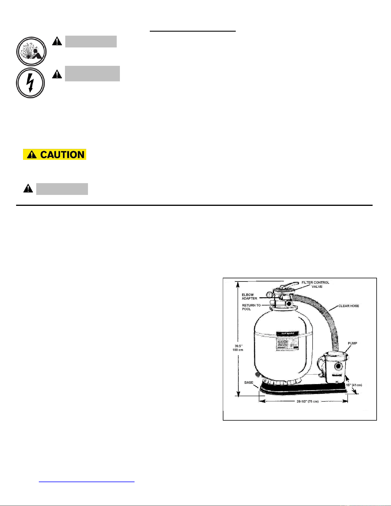
1. The filter system should be installed, not more than 6 feet above pool water level, on a level concrete slab, very firm ground, or
equivalent, as recommended by your pool dealer. Position the filter so that the piping connections, control valve and winter drain
are convenient and accessible for operation, service and winterizing.
TYPICAL INSTALLATION
Page 4 of 8 MODEL S210T, S210T90 IS210T90 Rev D
WWW.HAYWARDPOOL.COM USE ONLY HAYWARD GENUINE REPLACEMENT PARTS
2. Assemble pump and pump mounting base, to the filter according to instructions packed with the base.
3. Loading sand media. Filter sand media is loaded through the top opening of the filter.
a. Loosen flange clamp and remove Filter Control Valve (if previously installed).
b. Cap internal pipe with sand shield to prevent sand from entering it. Be sure pipe is securely in place in bottom underdrain hub.
c. We recommend filling tank approximately 1/2 way with water to provide a cushioning effect when the filter sand is poured in.
This helps protect the underdrain laterals from excessive shock. (Be sure the winter drain cap is securely in place on drain pipe).
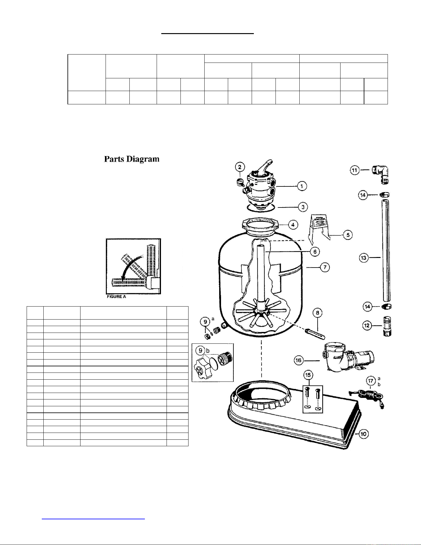
NOTE: Check to confirm all laterals are in the down position before loading with sand. (See Figure A.)
d. Carefully pour in correct amount and grade of filter sand, as specified. (Be sure center pipe remains centered in opening). Sand
surface should be leveled and should come to within 6" of the top of the filter tank. Remove sand shield from internal pipe.
4. Assemble Filter Control Valve to filter tank.
a. Loosely pre-assemble both halves of the clamp with one screw and one nut, turning the nut 2 or 3 turns. Do not tighten. Wipe filter
flange clean.
b. Insert Filter Control Valve (with valve/flange O-ring in place) into the tank neck, taking care that the center pipe slips into the hole
in the bottom of the valve. Install clamp around tank and valve flange and assemble second screw and nut. Tighten just enough so
that the valve may be rotated on tank for final positioning.
c. Carefully screw pressure gauge, with pipe tape, into 1/4"NPT tapped hole in valve body. Do not over tighten.
d. Wrap two turns of Teflon pipe sealant tape manufactured for plastic pipe, on the Straight adapter (12 on Fig B) and the Elbow
adapter (11), starting in the clockwise direction at the first full thread with a half width overlap for the full effective thread length.
e. Carefully start the threaded Straight adapter (12) into the pump (16) discharge (Top Port) and hand tighten. Further tightening
may not be needed to make a leak-proof joint. However, never tighten more than ½ to 1 ½ turns past hand tight to avoid failure
due to over tightening the joint.
f. Carefully start the threaded Elbow adapter (11) into the Control Valve (1) port marked PUMP and hand tighten. Further
tightening may not be needed to make a leak-proof joint. However, never tighten more than ½ to 1 ½ turns past hand tight to
avoid failure due to over tightening the joint.
g. Place two hose clamps (14) over clear hose (13). Fit hose over straight and elbow adapters and secure with the clamps. (HINT:
If it is difficult to fit hose over adapters, place hose in hot water for several minutes. Be Careful HOT WATER can burn you).
After the hose connections are made, tighten valve flange clamp with screwdriver, tapping around clamp with screwdriver handle
to help seat valve flange clamp. Please be sure to place the vinyl protector caps over the ends of the screws.
5. Make return to pool pipe connection to control valve opening marked RETURN and complete other necessary plumbing
connections, suction lines to pump, waste, etc.
6. Make electrical connections to pump per Pump Owners Guide instructions.
7. To prevent water leakage, be sure winter drain cap is securely in place and all pipe connections are tight.
INITIAL START-UP OF FILTER
1. Be sure correct amount of filter sand media is in tank and that all connections have been made and are secure.
2. Depress Vari-Flo control valve handle and rotate to BACKWASH* position. (To prevent damage to control valve seal, always
depress handle before turning.)
3. Prime and start pump according to pump instructions (be sure all suction and return lines are open), allowing the filter tank to fill with
water.
WARNING: ALL SUCTION AND DISCHARGE VALVES MUST BE OPEN WHEN
STARTING THE SYSTEM. FAILURE TO DO SO COULD CAUSE SEVERE PERSONAL INJURY.
Once water flow is steady out the waste line, run the pump for at least 2 minutes. The initial back-washing of the filter is
recommended to remove any impurities or fine sand particles in the sand media.
4. Turn pump off and set valve to RINSE position. Start pump and operate until water in sight glass is clear—about 1/2 to 1 minute.
Turn pump off, set valve to FILTER position and restart pump. Your filter is now operating in the normal filter mode, filtering particles
from the pool water.
5. Adjust pool suction and return valves to achieve desired flow. Check system and filter for water leaks and tighten connections, bolts,
nuts, as required.
6. Note the initial pressure gauge reading when the filter is clean. (It will vary from pool to pool depending upon the pump and general
piping system). As the filter removes dirt and impurities from the pool water, the accumulation in the filter will cause the pressure to
rise and flow to diminish. When the pressure gauge reading is 8-10 PSI (0.55-0.69 BAR) higher than the initial "clean" pressure you
noted, it is time to backwash (clean) the filter (see BACKWASH under Filter Control Valve Functions.)
NOTE: During initial clean-up of the pool water it may be necessary to backwash frequently due to the unusually
heavy initial dirt load in the water.
Page 5 of 8 MODEL S210T, S210T90 IS210T90 Rev D
WWW.HAYWARDPOOL.COM USE ONLY HAYWARD GENUINE REPLACEMENT PARTS
SPECIFICATIONS
MODEL
NUMBER
EFFECTIVE
FILTRATION
AREA
MAXIMUM
WORKING
PRESSURE
REQUIRED CLEARANCE
MEDIA REQUIRED
SIDE
ABOVE
TYPE
AMOUNT
FT
2
M
2
PSI
BAR
INCH
MM
INCH
MM
FILTER
SAND**
LBS
KG
S210T
S210T90
2.2
.20
40
2.7
18
460
18
460
0.45-0.55mm
200
90
**Also known as No. 20 or No. ½ Silica Sand.
FIGURE B
TABLE 1
Ref
No
Part No
Description
NO.
REQ’D
1
SP0714T
MULTIPORT VALVE
1
2
ECX27081
PRESSURE GAUGE
1
3
GMX600F
VALVE/TANK O-RING
1
4
GMX600N
FLANGE CLAMP (VALVE-TANK)
1
5
SX202S
SAND SHIELD
1
6
SX210DA
LATERAL ASSEMBLY W/PIPE
1
7
SX210AA2
FILTER TANK W/LATERAL ASSY
1
8
SX240DN
LATERAL-ONE PIECE
10
9a
SX180HG
DRAIN CAP ASSY (1 5/16” DIA)
9b
SX180LA
DRAIN CAP ASSY (1 3/4” DIA)
1
10
SX180K
SYSTEM MOUNTING BASE
1
11
SPX11050Z4
1 ½” ELBOW ADAPTER
1
12
SPX1091Z2
1 ½” STRAIGHT HOSE ADAPTER
1
13
SX160Z3
HOSE
1
14
ECX18028
HOSE CLAMP
2
15
ECX1108A
5/16” X 3/4” MOUNTING SCREW KIT
2
16
POWER-FLO MATRIX PUMP
1
17a
SPX1250WA
6 FT CORD SET
17b
SPX1550WA1
3 FT TWIST LOCK CORD SET
NOTE: The system Base has provisions for
mounting optional timer and optional Hayward
chlorine feeder

Page 6 of 8 MODEL S210T, S210T90 IS210T90 Rev D
WWW.HAYWARDPOOL.COM USE ONLY HAYWARD GENUINE REPLACEMENT PARTS
KEEP SAFETY LABELS IN GOOD
CONDITION AND REPLACE IF MISSING
OR DAMAGED.
IMPORTANT: To prevent unnecessary strain on
piping system and valving, always shut off pump
before switching Filter Control Valve positions.
To prevent damage to the pump and filter and for proper
operation of the system, clean pump strainer and
skimmer baskets regularly.
FILTER CONTROL VALVE FUNCTIONS
FILTER—Set valve to FILTER for normal filtering. Also
use for regular vacuuming.
BACKWASH—For cleaning filter. When filter pressure
gauge rises 8-10 PSI (0.55-0.69 BAR) above start-up
(clean pressure):
Stop the pump, set valve to BACKWASH. Start pump
and backwash until water in sight glass is clear.
Approximately 2 minutes or less depending on dirt
accumulation. Proceed to RINSE.
RINSE—After backwashing, with pump off, set valve to
RINSE. Start pump and operate for about 1/2 to 1 minute.
This ensures that all dirty water from backwashing is
rinsed out of the filter to waste, preventing possible return
to the pool. Stop pump, set valve to FILTER, and start
pump for normal filtering.
WASTE—To bypass filter for draining or lowering water
level and for vacuuming heavy debris directly to waste.
RECIRCULATE—Water is recirculated through the pool
system, bypassing the filter.
CLOSED—Shuts off flow from pump to filter.
VACUUMING—Vacuuming can be performed directly into
the filter. When vacuuming heavy debris loads, set valve
to WASTE position to bypass the filter and vacuum
directly out to waste.
'NOTE: For new concrete or gunite pools, or where there is a large amount
of plaster dust or debris—start filter in FILTER position (not
BACKWASH) to prevent clogging of underdrain laterals.
HAYWARD
®
LIMITED WARRANTY
This equipment was inspected before shipment from our plant. To original purchasers of this equipment, Hayward
Pool Products, 620 Division Street, Elizabeth, New Jersey, warrants its products free from defects in materials and
workmanship for a period of ONE (1) year from the date of purchase.
Parts which fail or become defective during the warranty period, except as a result of freezing, negligence, improper
installation, use, or care, shall be repaired or replaced, at our option, without charge, within 90 days of the receipt of
defective product, barring unforeseen delays.
To obtain warranty replacements or repair, defective components or parts should be returned, transportation paid, to
the place of purchase, or to the nearest authorized Hayward service center. For further Hayward dealer or service
center information, contact Hayward customer service department. No returns may be made directly to the factory
without the express written authorization of Hayward Pool Products, Inc.
To original purchasers of this equipment, Hayward Pool Products, Inc. warrants its vacuum release systems to be
free from defects in materials and workmanship for a period of ONE (1) year from the date of purchase.
Filters which become defective during the warranty period, except as a result of freezing, negligence, improper
installation, use or care, shall be repaired or replaced, at our option, without charge.
All other conditions and terms of the standard warranty apply.
Hayward shall not be responsible for cartage, removal and/or reinstallation labor or any other such costs incurred in
obtaining warranty replacements.
The Hayward Pool Products warranty does not apply to components manufactured by others. For such products, the
warranty established by the respective manufacturer will apply.
Some states do not allow a limitation on how long an implied warranty lasts, or the exclusion or limitation of
incidental or consequential damages, so the above limitation or exclusion may not apply to you.
This warranty gives you specific legal rights, and you may also have other rights, which vary from state to state.
Hayward Pool Products
620 Division Street
*Supersedes all previous publications. Elizabeth, NJ 07207

Page 7 of 8 MODEL S210T, S210T90 IS210T90 Rev D
WWW.HAYWARDPOOL.COM USE ONLY HAYWARD GENUINE REPLACEMENT PARTS
WINTERIZING
1. Completely drain tank by unscrewing drain cap at
base of filter tank. Leave cap off during winter.
2. Depress Vari-Flo control valve handle and rotate so
as to set pointer on valve top between any two
positions. This will allow water to drain from the
valve. Leave valve in this "inactive" position.
3. Drain and winterize pump according to pump
instructions.
SERVICE & REPAIRS
Consult your local authorized Hayward dealer or service
center. No returns may be made directly to the factory
without the expressed authorization of Hayward Pool
Products.
PLEASE REALIZE:
Pure, clear swimming pool water is a combination of two
factors—adequate filtration and proper water chemistry
balance. One without the other will not give the clean
water you desire.
Your filter system is designed for continuous operation.
However, this is not necessary for most swimming pools.
You can determine your filter operation schedule based
on your pool size and usage. Be sure to operate your
filtration system long enough each day to obtain at least
one complete turnover of your pool water.
To properly sanitize your pool, maintain a free chlorine
level of 1 to 3 ppm and a pH range of 7.2 to 7.8.
Insufficient chlorine or an out of balance pH level will
permit algae and bacteria to grow in your pool and make
it difficult for your filter to properly clean the pool water.
PROBLEM SOLVING LIST
LOW WATER FLOW
SHORT FILTER CYCLES
POOL WATER WON'T CLEAR UP
REMEDY
1. Check skimmer and pump
1. Check for algae in pool and
1. Check chlorine, pH and total
strainer baskets for debris.
2. Check for restrictions in
intake and discharge lines.
3. Check for air leak in intake
line (indicated by bubbles
returning to pool).
4. Backwash filter.
superchlorinate as required.
2. Be sure chlorine and pH
levels are in proper range
(adjust as required).
3. Check surface of filter sand
for crusting or caking
(remove 1 " of sand if
necessary).
alkalinity levels and adjust
as required.
2. Be sure flow rate through
filter is sufficient.
3. Operate filter for longer periods.
4. Be sure Vari-Flo valve is set
on "Filter" position.

Page 8 of 8 MODEL S210T, S210T90 IS210T90 Rev D
WWW.HAYWARDPOOL.COM USE ONLY HAYWARD GENUINE REPLACEMENT PARTS
DETACH HERE: Fill out bottom portion completely and mail within 10 days of purchase/installation, or
REGISTER ONLINE AT WWW.HAYWARDNET.COM.
------------------------------------------------------------------------------------------------------------
Mail to: Hayward Pool Products., 620 Division Street, Elizabeth, NJ 07207, Attn: Warranty Dept.
Warranty Registration Card
Name__________________________________________________ Years pool has been in service □ less than 1 □ 1-3 □ 3-5 □ 5-10
Address________________________________________________ Purchased from:
City______________________ State_________ Zip____________ Company name________________________________________________
E-mail Address__________________________________________ Address_______________________________________________________
City__________________________ State_________ Zip_______________
Product Purchased ______________________________________
Product Serial No. _______________________________________
Please send me more information on these other
□ New Installation □ Replacement products from Hayward:
Type of Above-ground Pool: □ Pump □ Filter □ Automatic Pool Cleaner □ Light
□ Vinyl □ Fiberglass □ Other □ Chlorinator □ Skimmer □ Heater □ Heat Pump
Size of Pool____________________________________ □ Salt/Chlorine Generator □ Controls
REGISTER YOUR WARRANTY ON-LINE AT WWW.HAYWARDNET.COM
© Hayward Pool Products. 2007 All rights reserved.
DATE OF INSTALLATION ____________________
PURCHASED FROM _______________________
MODEL ___________________________
SERIAL NUMBER _______________________
▲Retain this Warranty Certificate in a safe and convenient location
for your records.
MAXIMUM RECOMMENDED SYSTEM FLOW RATE BY PIPE SIZE
Pipe Size
[mm]
Flow rate
GPM [Liter/Min]
Pipe Size
[mm]
Flow rate
GPM [Liter/Min]
Pipe Size
[mm]
Flow rate
GPM [Liter/Min]
1”
[32]
20
[75]
1 ½”
[50]
45
[170]
2 ½”
[75]
110
[415]
1 ¼”
[40]
30
[110]
2”
[63]
80
[300]
3”
[90]
160
[600]
TABLE 2
PRODUCT REGISTRATION
(Retain For Your Records)
SUGGESTED POOL CHEMISTRY LEVELS
pH
7.2 to 7.8
TOTAL ALKALINITY
80 to 120 ppm
CALCIUM HARDNESS
200 TO 400 ppm
COMBINED CHLORINE
0.2 ppm Maximum
CHLORINE (STABILIZED)
1.0 to 3.0 ppm
CHLORINE STABILIZER
(Cyanuric Acid)
60 to 80 ppm