

40V SV20 SERIES 30CM CORDLESS GRASS
STRIMMER BODY ONLY
MODEL NO: CP40VGS
Thank you for purchasing a Sealey product. Manufactured to a high standard, this product will, if used according to these instructions,
and properly maintained, give you years of trouble free performance.
IMPORTANT: PLEASE READ THESE INSTRUCTIONS CAREFULLY. NOTE THE SAFE OPERATIONAL REQUIREMENTS, WARNINGS &
CAUTIONS. USE THE PRODUCT CORRECTLY AND WITH CARE FOR THE PURPOSE FOR WHICH IT IS INTENDED. FAILURE TO DO
SO MAY CAUSE DAMAGE AND/OR PERSONAL INJURY AND WILL INVALIDATE THE WARRANTY. KEEP THESE INSTRUCTIONS SAFE
FOR FUTURE USE.
1. SAFETY
1.1. GENERAL SAFETY
WARNING! Read all safety warnings and all instructions. Failure to follow the warnings and instructions may result in electric shock,
re and/or serious injury.
9 Be familiar with the controls and proper use of the equipment.
WARNING! Cutting elements continue to rotate after the motor is switched o.
8 DO NOT allow children or people unfamiliar with the instructions to use the machine. Local regulations may restrict the age of the operator.
8 Never operate the machine while people, especially children, or pets are nearby.
9 Only use the machine in daylight or good articial light.
9 Before using the machine and after any impact, check for signs of wear or damage and repair as necessary.
9 Take care against injury from any device tted for trimming the lament line length. After extending new cutter line always return the
machine to its normal operating position before switching on.
8 DO NOT t metal cutting elements.
8 Never replace the non-metallic cutting means with metallic cutting means
9 Never allow children , persons with reduced physical, sensory or mental capabilities or lack of experience and knowledge or people
unfamiliar with these instructions to use the machine, local regulations may restrict the age of the operator.
9 Use the tool with the utmost care and attention.
9 Operate the tool only if you are in good physical condition. Perform all work calmly and carefully. Use common sense and keep in mind
that the operator or user is responsible for accidents or hazards occurring to other people or their property.
8 DO NOT operate the tool when tired, feeling ill or under the inuence of alcohol or drugs.
9 The tool should be switched o immediately if it shows any signs of unusual operation.
9 Keep ngers away from switch trigger when not operating the tool and when moving from one operating position to another.
9 Dress Properly. The clothing worn should be functional and appropriate, i.e. it should be tight-tting but not cause hindrance.
8 DO NOT wear either jewellery or clothing which could become entangled with high grass. Wear protective hair covering to contain long hair.
9 When using the tool, always wear sturdy shoes with a non-slip sole. This protects against injuries and ensures a good footing.
9 Always wear protective goggles to protect your eyes from injury when using power tools. The goggles must comply with local regulations.
9 It is an employer’s responsibility to enforce the use of appropriate safety protective equipments by the tool operators and by other per-
sons in the immediate working area.
9 Always be sure of your footing on slopes and when walking with the machine. Never run.
9 Disconnect the supply when the following occurs: the machine is left by the user; before clearing a blockage; before checking, cleaning
or working on the machine; after striking a foreign object to inspect the machine for damage; if the machine starts to vibrate abnormally.
8 Never operate the machine with a defective guard or shield, or without safety devices, or if the cord is damaged or worn.
8 Avoid using the machine in bad weather conditions, especially when there is a risk of lightning.
1.2. ELECTRICAL AND BATTERY SAFETY
8 DO NOT use the tool in damp or wet locations or expose it to rain. Water entering the tool will increase the risk of electric shock.
9 Recharge only with the charger specied by the manufacturer. A charger that is suitable for one type of battery pack may create a risk
of re when used with another battery pack.
9 Use power tools only with specically designated battery packs. Use of any other battery packs may create a risk of injury and re.
9 When battery pack is not in use, keep it away from other metal objects, like paper clips, coins, keys, nails, screws or other small metal
objects, that can make a connection from one terminal to another. Shorting the battery terminals together may cause burns or a re.
9 Under abusive conditions, liquid may be ejected from the battery; avoid contact. If contact accidentally occurs, ush with water. If liquid
contacts eyes, seek medical help. Liquid ejected from the battery may cause irritation or burns.
8 DO NOT dispose of the battery(ies) in a re. The cell may explode. Check with local codes for possible special disposal instructions
8 DO NOT open or mutilate the battery(ies). Released electrolyte is corrosive and may cause damage to the eyes or skin. It may be toxic
if swallowed.
8 DO NOT charge battery in rain, or in wet locations.
9 Non-rechargeable batteries are not to be recharged.
9 Rechargeable batteries are to be removed from the appliance before being charged.
8 Dierent types of batteries or new and used batteries are not to be mixed.
9 Batteries are to be inserted with the correct polarity.
9 Exhausted batteries are to be removed from the appliance and safely disposed of.
Refer to
instructions
Wear eye
protection
Wear ear
protection
Wear protective
gloves
DO NOT
expose to rain
WARNING!
Thrown objects.
Keep
bystanders
away.
CP40VGS Issue 4 12/01/24
Original Language Version
© Jack Sealey Limited

9 If the appliance is to be stored unused for a long period, the batteries should be removed.
9 The supply terminals are not to be short-circuited.
1.3. STARTING UP THE TOOL
9 Make sure that there are no children or other people within a working range of 15 meters (50 ft), also pay attention to any animals in
the working vicinity. Otherwise stop using the tool.
9 Before use always check that the tool is safe for operation. Check the security of the cutting tool and the guard and the switch trigger/
lever for easy and proper action. Check for clean and dry handles and test the on/o function of the switch.
9 Check damaged parts before further use of the tool. A guard or other part that is damaged should be carefully checked to determine
that it will operate properly and perform its intended function. Check for alignment of moving parts, binding of moving parts, breakage
of parts, mounting, and any other condition that may aect its operation. A guard or other part that is damaged should be properly
repaired or replaced by our authorized service centre unless indicated elsewhere in this manual.
9 Switch on the motor only when hands and feet are away from the cutting tool.
9 Before starting make sure that the cutting tool has no contact with hard objects such as branches, stones etc. as the cutting tool will
revolve when starting.
9 Make sure there are no electrical cables, water pipes, gas pipes etc. that could cause a hazard if damaged by use of the tool.
1.4. METHOD OF OPERATION
8 DO NOT operate the machine with damaged guards or without the guards in place.
9 Only use the tool in good light and visibility. During the winter season beware of slippery or wet areas, ice and snow (risk of slipping).
9 Take care against injury to feet and hands from the cutting tool.
9 Keep hands and feet away from the cutting means at all times and especially when switching on the motor.
8 DO NOT cut above waist height.
8 DO NOT stand on a ladder and run the tool.
8 DO NOT work on unstable surfaces.
8 DO NOT overreach. Keep proper footing and balance at all times.
9 Remove sand, stones, nails etc. found within the working range. Foreign particles may damage the cutting tool and can cause to be
thrown away, resulting in a serious injury.
9 Should the cutting tool hit stones or other hard objects, immediately switch o the motor and inspect the cutting tool.
9 Before commencing cutting, the cutting tool must have reached full working speed.
9 During operation always hold the tool with both hands. DO NOT hold the tool with one hand during use. Always ensure a safe footing.
8 Except in case of emergency, DO NOT drop or cast the tool to the ground or this may severely damage the tool.
8 DO NOT drag the tool on the ground when moving from place to place, the tool may become damaged if moved in this manner.
9 Always remove the battery cartridge from the tool: whenever leaving the tool unattended; before clearing a blockage; before checking,
cleaning or working on the tool; before making any adjustments, changing accessories or storing; whenever the tool starts vibrating
unusually; whenever transporting the tool.
8 DO NOT force the tool. It will do the job better and with less likelihood of a risk of injury at the rate for which it was designed.
8 DO NOT operate power tools in explosive atmospheres, such as in the presence of ammable liquids, gases or dust. Power tools
create sparks which may ignite the dust or fumes.
9 Take a rest to prevent loss of control caused by fatigue. We recommend to take a 10 to 20-minute rest every hour.
8 DO NOT use the tool on steep slopes.
9 The shoulder harness must be used during operation, if supplied with the tool.
1.5. MAINTENANCE INSTRUCTIONS
9 The condition of the cutting tool, protective devices and shoulder harness must be checked before commencing work.
9 Turn o the motor and remove the battery cartridge before carrying out maintenance, replacing the cutting tool and cleaning the tool.
9 After use, disconnect the battery cartridge from the tool and check for damage.
9 Check for loose fasteners and damaged parts such as nearly halfway cut-o state in the cutting tool.
9 When not in use store the equipment in a dry location that is locked up or out of children’s reach.
9 Use only the manufacturer’s recommended replacement parts and accessories.
9 Always ensure that ventilation openings are kept clear of debris.
9 Inspect and maintain the tool regularly, especially before/after use. Have the tool repaired only by our authorized service centre.
9 Keep handles dry, clean and free from oil and grease.
WARNING! DO NOT let comfort or familiarity with product (gained from repeated use) replace strict adherence to safety rules for the
subject product. MISUSE or failure to follow the safety rules stated in this instruction manual may cause serious personal injury.
1.6. SAFETY INSTRUCTIONS FOR BATTERY CARTRIDGE
9 Before using battery cartridge, read all instructions and cautionary markings on battery charger, battery, and the product.
8 DO NOT disassemble battery cartridge.
9 If operating time has become excessively shorter, stop operating immediately. It may result in a risk of overheating, possible burns and
even an explosion.
9 If electrolyte gets into your eyes, rinse them out with clear water and seek medical attention right away. It may result in loss of your eyesight.
8 DO NOT short the battery cartridge.
8 DO NOT touch the terminals with any conductive material.
8 Avoid storing battery cartridge in a container with other metal objects such as nails, coins, etc.
8 DO NOT expose battery cartridge to water or rain.
9 A battery short can cause a large current ow, overheating, possible burns and even a breakdown.
8 DO NOT store the tool and battery cartridge in locations where the temperature may reach or exceed 50°C (122°F).
8 DO NOT incinerate the battery cartridge even if it is severely damaged or is completely worn out. The battery cartridge can explode in a re.
8 DO NOT drop or strike battery.
8 DO NOT use a damaged battery.
9 The contained lithium-ion batteries are subject to the Dangerous Goods Legislation requirements. For commercial transports e.g. by
third parties, forwarding agents, special requirement on packaging and labelling must be observed.
9 For preparation of the item being shipped, consulting an expert for hazardous material is required. Please also observe possibly more detailed
national regulations. Tape or mask o open contacts and pack up the battery in such a manner that it cannot move around in the packaging.
9 Follow your local regulations relating to disposal of battery.
9 Use the batteries only with the products specied by Sealey. Installing the batteries to non-compliant products may result in a re,
excessive heat, explosion, or leak of electrolyte.
CP40VGS Issue 4 12/01/24
Original Language Version
© Jack Sealey Limited
CAUTION: Only use genuine Sealey batteries. Use of non-genuine Sealey batteries, or batteries that have been altered, may result in
the battery bursting causing res, personal injury and damage. It will also void the warranty for the Sealey tool and charger.
1.7. TIPS FOR MAINTAINING MAXIMUM BATTERY LIFE
9 Charge the battery cartridge before completely discharged.
9 Always stop tool operation and charge the battery cartridge when you notice less tool power.
8 Never recharge a fully charged battery cartridge. Overcharging shortens the battery service life.
9 Charge the battery cartridge with room temperature at 5°C - 45°C .
9 Let a hot battery cartridge cool down before charging it.
2. INTRODUCTION
Designed for the professional, oering heavy-duty, high performance, durable tools with lightweight composite designs for superior
control and comfort. Operates using 2 x 20V batteries from the Sealey SV20 Series (batteries must be of the same Ah rating) Wide
cutting width of 30cm. Bump feed line. 2-in-1 function tted with wheels for grass strimming and edging. 90° rotating head allows for a
comfortable cutting angle.
3. SPECIFICATION
Model No: CP40VGS
Battery: 20V 2Ah - 6Ah Lithium-ion (not included) Noise Power/Pressure: 95/84dB(A)
Cutting Mechanism: Bump Feed Line No-Load Speed: 6700rpm
Cutting Width: 300mm Vibration/Uncertainty: 2.75/1.5m/s²
Nett Weight: 2.6kg Voltage: 40V
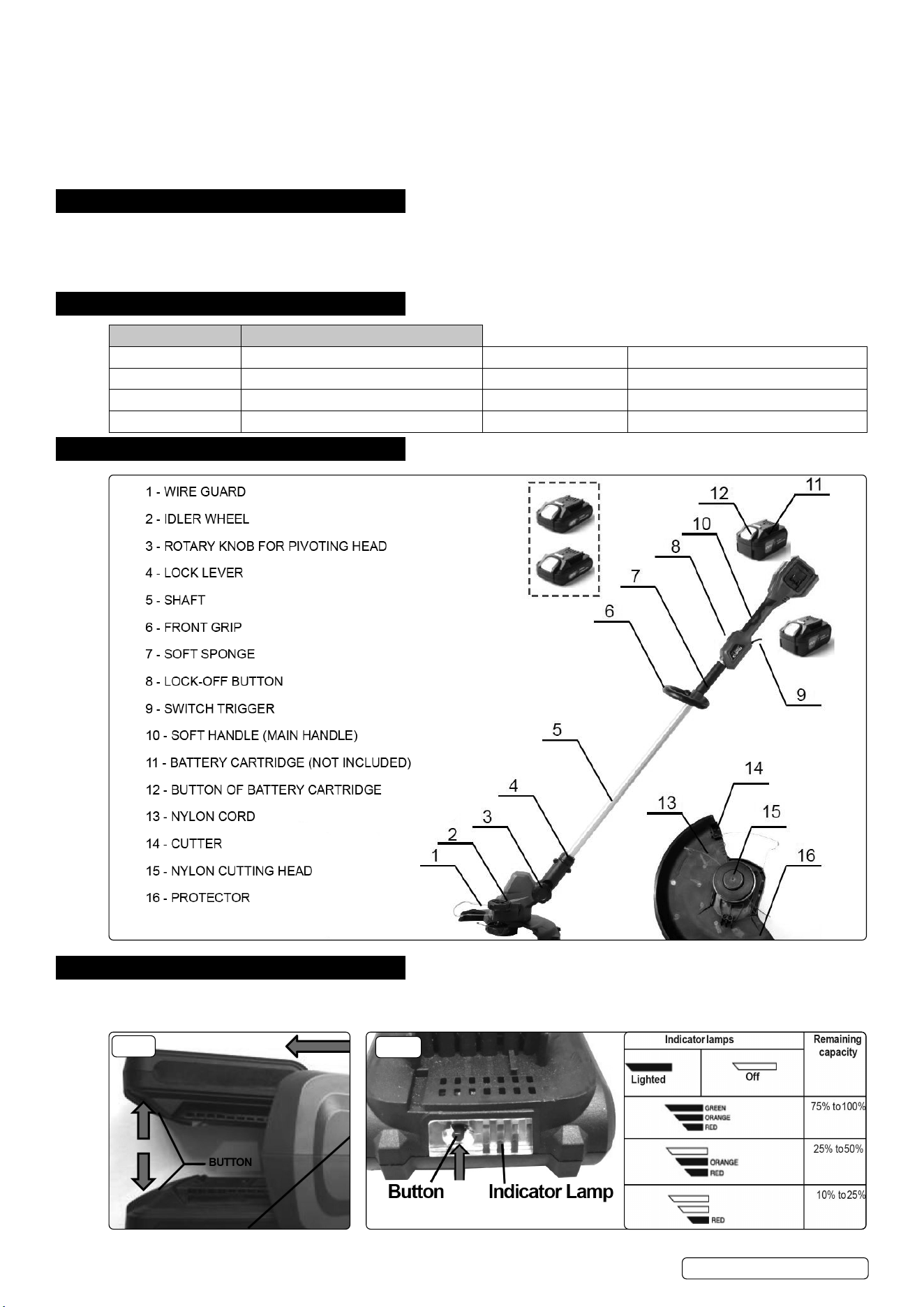
4. CONTENTS
5. ASSEMBLY
WARNING! Always be sure that the tool is switched o and the battery cartridges are removed before adjusting or checking function on
the tool. Failure to switch o and remove the battery cartridges may result in serious personal injury from accidental start-up.
FIG.2
FIG.1
CP40VGS Issue 4 12/01/24
Original Language Version
© Jack Sealey Limited
5.1. INSTALLING OR REMOVING BATTERY CARTRIDGES (FIG.1)
CAUTION: Always switch o the tool before installing or removing the battery cartridges.
CAUTION: Hold the tool and the battery cartridge rmly when installing or removing battery cartridge. Failure to hold the tool and the
battery cartridge rmly may cause them to slip o your hands and result in damage to the tool and battery cartridge and a personal injury.
5.1.1. To remove the battery cartridge, slide it from the tool while sliding the button on the front of the cartridge.
5.1.2. To install the battery cartridge, align the tongue on the battery cartridge with the groove in the housing and slip it into place. Insert it all
the way until it locks in place with a little click.
CAUTION: Always install the battery cartridge fully. If not, it may accidentally fall out of the tool, causing injury to you or someone
around you.
CAUTION: DO NOT install the battery cartridge forcibly. If the cartridge does not slide in easily, it is not being inserted correctly.
NOTE: The tool does not work with only one battery cartridge.
NOTE: Pay attention to the position of your ngers when installing the battery. The button will be depressed unintentionally.
5.2. BATTERY CAPACITY (FIG.2)
5.2.1. Press the check button on the battery cartridge to indicate the remaining battery capacity. The indicator lamps light up for few seconds.
NOTE: Depending on the conditions of use and the ambient temperature, the indication may dier slightly from the actual capacity.
5.3. TOOL / BATTERY PROTECTION SYSTEM
The tool is equipped with a tool/battery protection system. This system automatically cuts o power to the motor to extend tool and
battery life. The tool will automatically stop during operation if the tool or battery is placed under one of the following conditions:
5.3.1. OVERLOAD PROTECTION
When the battery is operated in a manner that causes it to draw an abnormally high current, the tool automatically stops. In this
situation, turn the tool o and stop the application that caused the tool to become overloaded. Then turn the tool on to restart.
5.3.2. OVERHEAT PROTECTION
When the battery is overheated, the tool stops automatically. In this case, let the tool and battery cool before turning the tool on again.
5.3.3. OVERDISCHARGE PROTECTION
When the battery capacity is not enough, the tool stops automatically. In this case, remove the battery from the tool and charge the battery.
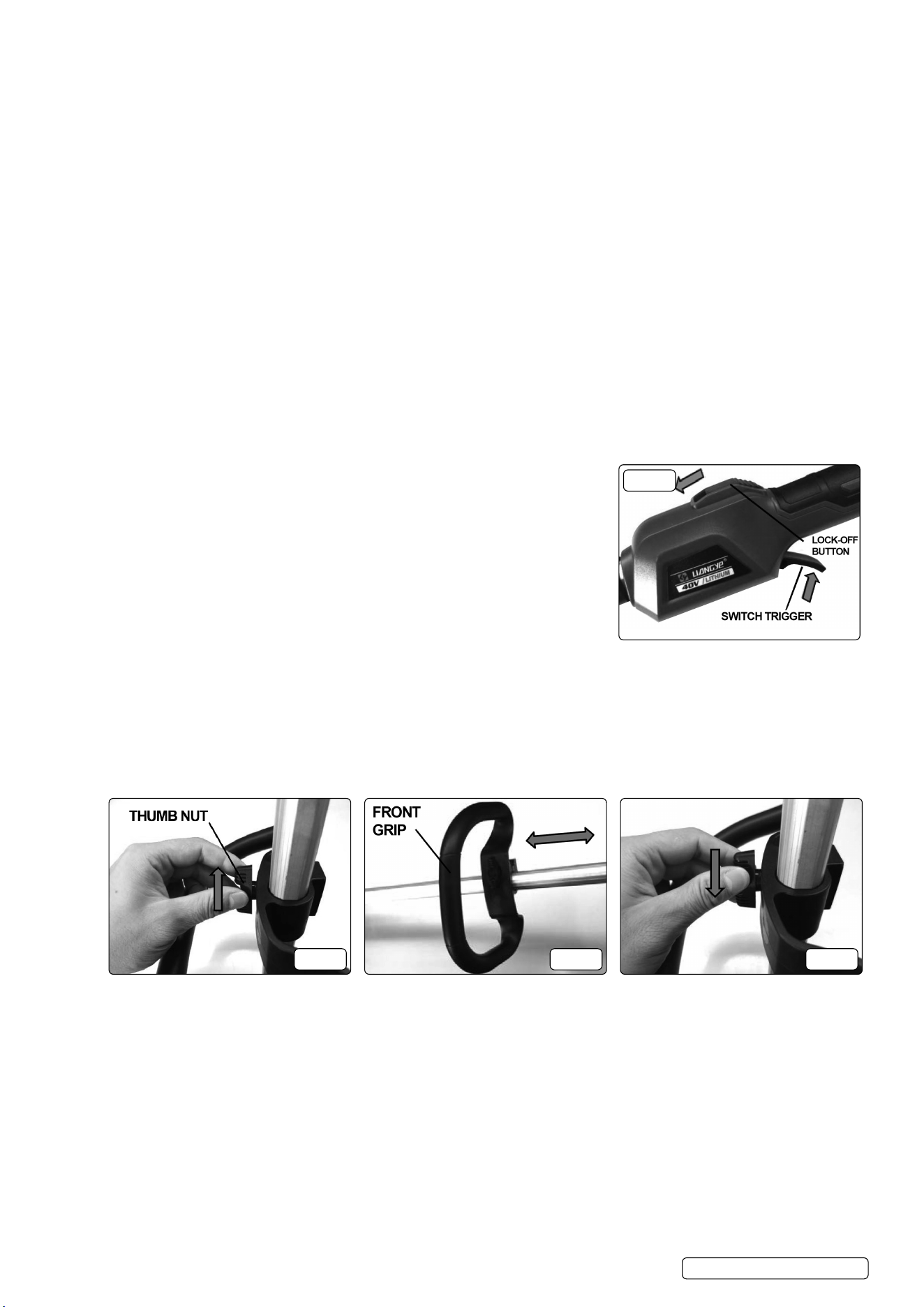
5.4. SWITCH ACTION (FIG.3)
WARNING! Before installing the battery cartridge into the tool, always check to see that
the switch trigger actuates properly and returns to the “OFF” position when released.
WARNING! For your safety, this tool is equipped with the lock-o button which prevents
the tool from unintended starting. Never use the tool if it starts when you pull the switch
trigger without pushing forward the lock-o button. Ask your Sealey Service Centre for
repairs.
WARNING! Never disable the lock function or tape down the lock-o button.
8 DO NOT pull the switch trigger forcibly without pushing forward the lock-o button. The
switch may break.
To prevent the switch trigger from being accidentally pulled, a lock-o button is provided.
To start the tool, push the lock-o button forward and then depress the switch trigger.
Release the switch trigger to stop.
5.5. ADJUSTING THE POSITION OF FRONT GRIP (FIG.4, 5 & 6)
CAUTION: Before adjusting the front grip, be sure to switch o the tool and remove the battery cartridge from the tool. Failure to do so
may cause a personal injury.
5.6. Adjust the position of the front grip so that you can hold the front grip when lowering your left hand.
5.7. To adjust the position of the front grip , turn clockwise to loosen enough the thumb nut, then adjust the position of the front grip as
desired, and then turn anticlockwise to tighten the thumb nut rmly.
CAUTION: After adjusting the front grip position, make sure that the front grip is rmly secured.
FIG.4 FIG.5 FIG.6
5.8. ADJUSTING THE HORIZONTAL ANGLE OF THE PIVOTING HEAD (FIG.7 & 8)
Adjust the horizontal angle of the pivoting head to suit the task at hand. To adjust the horizontal angle of the pivoting head, turn the
rotary knob for pivoting head clockwise so that the line mark on the rotary knob align with the “Unlock” mark on the pivoting head, then
turn the pivoting head clockwise or anticlockwise to adjust the angle.
5.8.1. When adjusted to your desired angle, turn the rotary knob so that the line mark align with the “Lock” mark to lock on. The angle can be
adjusted of total 90 degrees in 5 stages. Adjust as desired.
CAUTION: After adjusting the pivoting head, make sure that the pivoting head is rmly secured.
5.9. ADJUSTING THE VERTICAL ANGLE OF THE PIVOTING HEAD (FIG.9)
Adjust the vertical angle of the pivoting head when using the grass trimmer as an edger.
5.9.1. To adjust the vertical angle of the pivoting head, pull the pivoting head and then turn the shaft clockwise to adjust the angle.
5.9.2. When adjusted to the designated angle, the Lock lever will lock on in place automatically.
FIG.3
CP40VGS Issue 4 12/01/24
Original Language Version
© Jack Sealey Limited
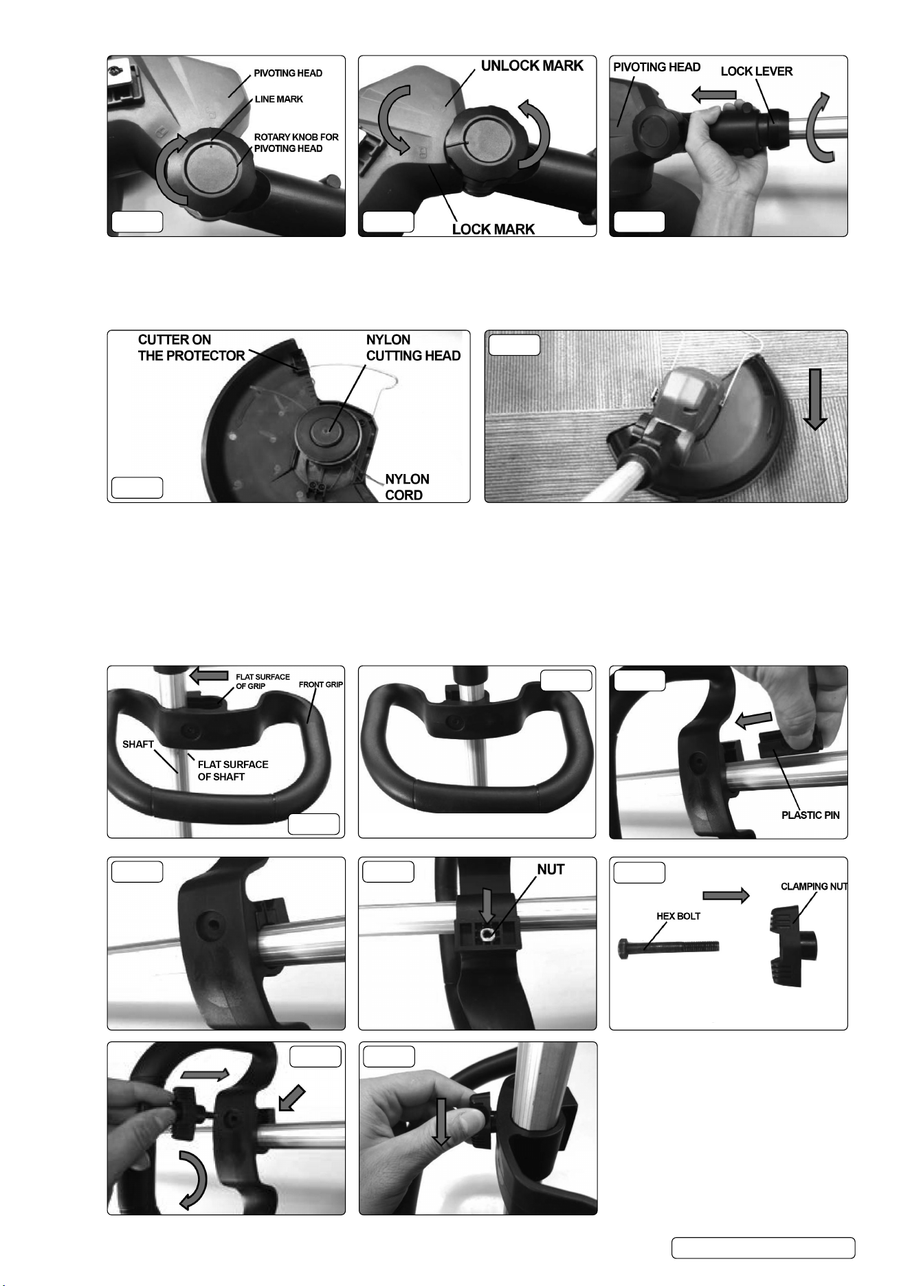
FIG.7 FIG.8 FIG.9
5.10. NYLON CUTTING HEAD (FIG.10 & 11)
NOTE: If the nylon cord does not feed out while start running the tool each time, rewind or replace the nylon cord by following the
procedures in this manual.
The nylon cutting head has a bump and feed mechanism. To feed the nylon cord, bump the cutting head against the ground while the
tool is running. As the nylon cord is feeding out, it will automatically be cut to the proper length by the cutter.
FIG.10
FIG.11
CAUTION: Always be sure that the tool is switched o and the battery cartridge is removed before carrying out any work on the tool.
CAUTION: Never start the tool unless it is completely assembled. Operation of the tool in a partially assembled state may result in
serious personal injury from accidental start-up.
5.11. INSTALLING THE FRONT GRIP
To install the front grip, perform the following steps:
5.11.1. Hold the shaft rmly and push the front grip hard to attach the front grip to the shaft as shown in g.12 & 13. Make sure that the at
surface of the shaft face to the at surface of the grip.
5.11.2. Hold the front grip and insert the plastic pin as shown in g.14.
5.11.3. Embed the nut onto the bottom of the front grip as shown in the g.16.
FIG.12
FIG.13 FIG.14
FIG.15 FIG.16
FIG.17
FIG.18 FIG.19
CP40VGS Issue 4 12/01/24
Original Language Version
© Jack Sealey Limited
5.11.4. Insert the hex bolt into the hole of the clamping nut (g.17).
5.11.5. Press against the nut and secure the front grip with the hex bolt and clamping nut (g.18).
CAUTION: Always make sure that the front grip is secured rmly (g.19). If not, the front grip may slide accidentally or come o from
the tool and result in personal injury during operation.
5.11.6. To uninstall the front grip, perform the installation procedure in reverse.
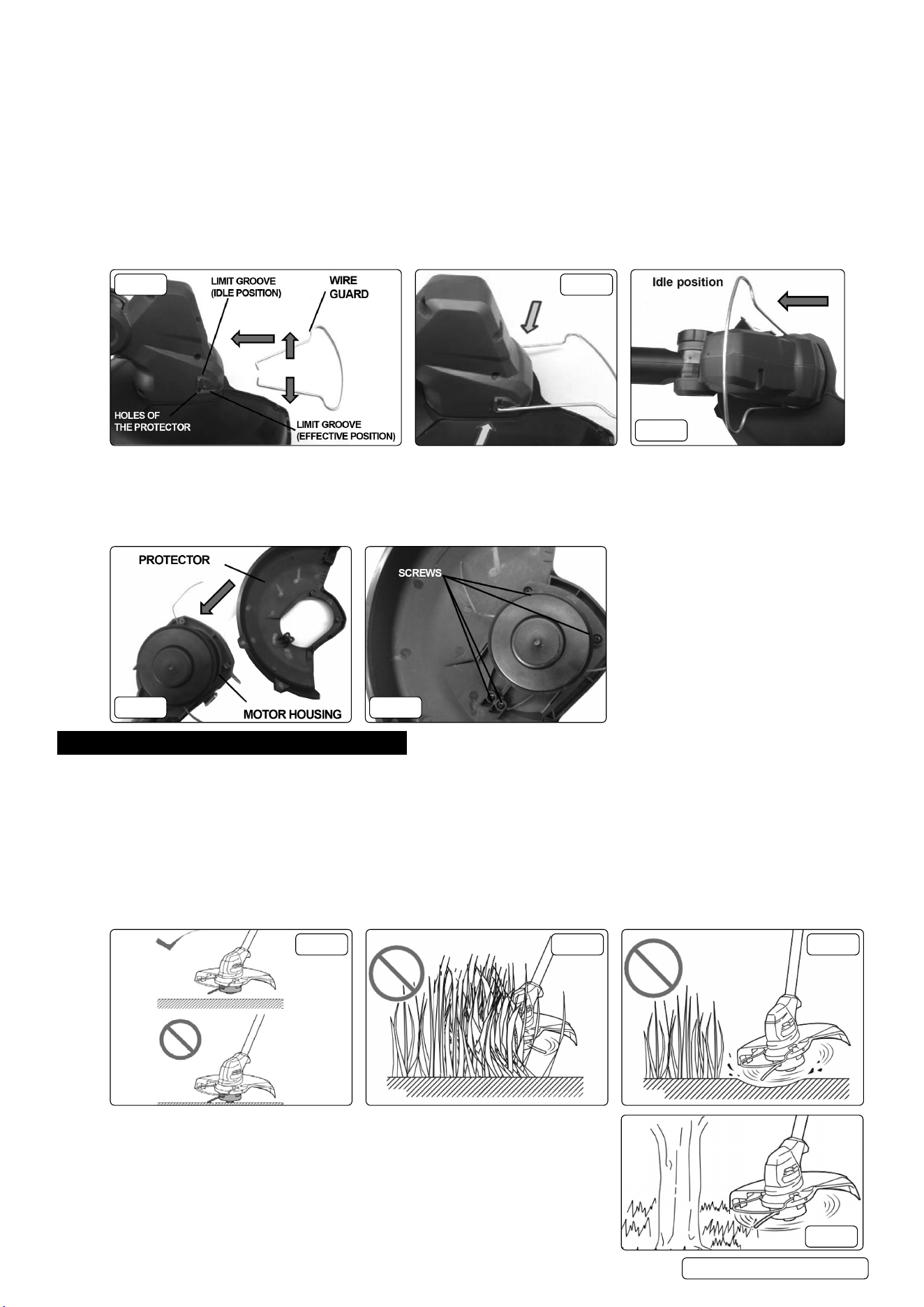
5.12. INSTALLING THE WIREGUARD (FIG.20, 21 & 22)
NOTE: DO NOT expand the wire guard outward too much. Otherwise it may break.
5.12.1. To reduce the risk of damaging the objects in front of the cutting head, attach the wire guard to the protector so that it controls the
cutting range.
5.12.2. Slightly expand the wire guard outward and then insert it into the holes of the protector (g.21).
5.12.3. Lift the wire guard down into the limit groove(eective position) or lift the wire guard up into the limit groove(idle position).
CAUTION: After installing the wire guard, make sure that the wire guard is rmly secured.
5.12.4. When wire guard is not in use, lift it up to the idle position (g.22).
FIG.20 FIG.21
FIG.22
5.13. INSTALLING/UNINSTALLING THE PROTECTOR (FIG.23 & 24)
CAUTION: Always make sure that the protector is secured rmly. If not, the protector may slide accidentally or come o from the tool
and result in personal injury during operation.
5.13.1. To install the protector, mount the protector by tting it on to the motor housing, and then secure it with four screws clockwise (g.24).
5.13.2. To uninstall the protector, perform the install steps in reverse.
FIG.23 FIG.24
6. OPERATION
6.1. CUTTING THE GRASS (FIG.25, 26 & 27)
6.1.1. Hold the grass trimmer at the angle of about 50° to the ground.
6.1.2. Move the grass trimmer from right to left slowly.
6.1.3. Cut the grass a few times from the top of the grass at the tip of the nylon cord .
NOTE: DO NOT cut high grass at a time. Cutting the high grass at a time near the root may cause the nylon cutting head to be
entangled by grass. This may cause the motor overload, resulting in damage to the grass trimmer.
NOTE: Use the grass trimmer without getting the spool into a contact with the ground surface. Using the spool contacting the ground
surface may cause the motor under overload resulting in damage to the grass trimmer (g.25).
8 DO NOT force the trimmer in densely growing grass (g.26).
8 DO NOT use the trimmer as if you dig out the ground (g.27).
FIG.25 FIG.26 FIG.27
6.2. CUTTING THE GRASS NEAR TREE, BLOCK, BRICK, OR STONE (FIG.28)
6.2.1. Hold and tilt the grass trimmer at a height where the spool does not touch the ground.
NOTE: When cutting the grass, move the grass trimmer around the tree or blocks so
that the nylon cord does not touch the tree or blocks. It is recommended to keep the tool
more than 5cm away from the tree or block. If the nylon cord touch the tree or block, the
nylon cord may be torn rapidly. If the nylon cord is torn in the spool, set the nylon cord
again referring to the replacement procedure in this manual.
FIG.28
CP40VGS Issue 4 12/01/24
Original Language Version
© Jack Sealey Limited
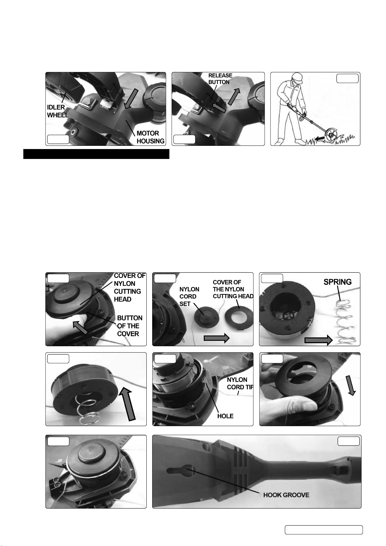
6.3. USING THE GRASS TRIMMER AS AN EDGER (FIG.29, 30 & 31)
6.3.1. An idler wheel is also provided for easy and better operation while using the grass trimmer as an edger.
6.3.2. To install the idler wheel, slide it onto the motor housing directly as far as it can go as shown in the gure (g.29)
6.3.3. To uninstall the idler wheel, depress the release button and pull out it directly as shown (g.30).
6.3.4. Adjust the vertical and horizontal angle of the pivoting head.
6.3.5. As shown in g.30, use the idler wheel to move the grass trimmer to cut the grass. You can cut the grass eciently by walking in
parallel along the bricks or blocks.
FIG.29 FIG.30
FIG.31
7. MAINTENANCE
WARNING! Danger of moving hazardous parts.
WARNING! Always switch o the tool and remove the battery cartridges before attempting to perform inspection or maintenance on the tool.
Failure to switch o and remove the battery cartridge may result in serious personal injury from accidental start-up.
NOTE: Never use gasoline, benzine, thinner, alcohol or the like. Discolouration, deformation or cracks may result.
To maintain product safety and reliability, repairs, any other maintenance or adjustment should be performed by Sealey Authorised
Centres, always using Sealey replacement parts. Maintenance should be performed when performance/function decreases.
7.1. REPLACING THE NYLON CORD SET
WARNING! Never use heavier line, metal wire, rope or the like. Use recommended nylon cord only, otherwise it may cause damage to
the tool and result in serious personal injury.
WARNING! Make sure that the cover of the nylon cutting head is secured to the housing properly as described below. Failure to properly
secure the cover may cause the nylon cord set to y apart resulting in serious personal injury.
When using up the nylon cord, you need to replace with a new nylon cord set. To replace a new nylon cord set, perform the following steps:
7.1.1. Depress the button of the cover both sides a little bit and then remove the cover and the old one in order (g.32 & 33).
7.1.2. Detach the spring and replace the old nylon cord set with a new and reinstall the spring to the original place (g.34 & 35).
7.1.3. Mount the new one onto the original position with the nylon cord tip through the two hole on both sides (g.36).
7.1.4. Depress the button of the cover both sides and inset it into the original position until it locks in place with a little click (g.37 & 38).
FIG.32 FIG.33 FIG.34
FIG.35 FIG.36 FIG.37
FIG.38
FIG.39
CP40VGS Issue 4 12/01/24
Original Language Version
© Jack Sealey Limited
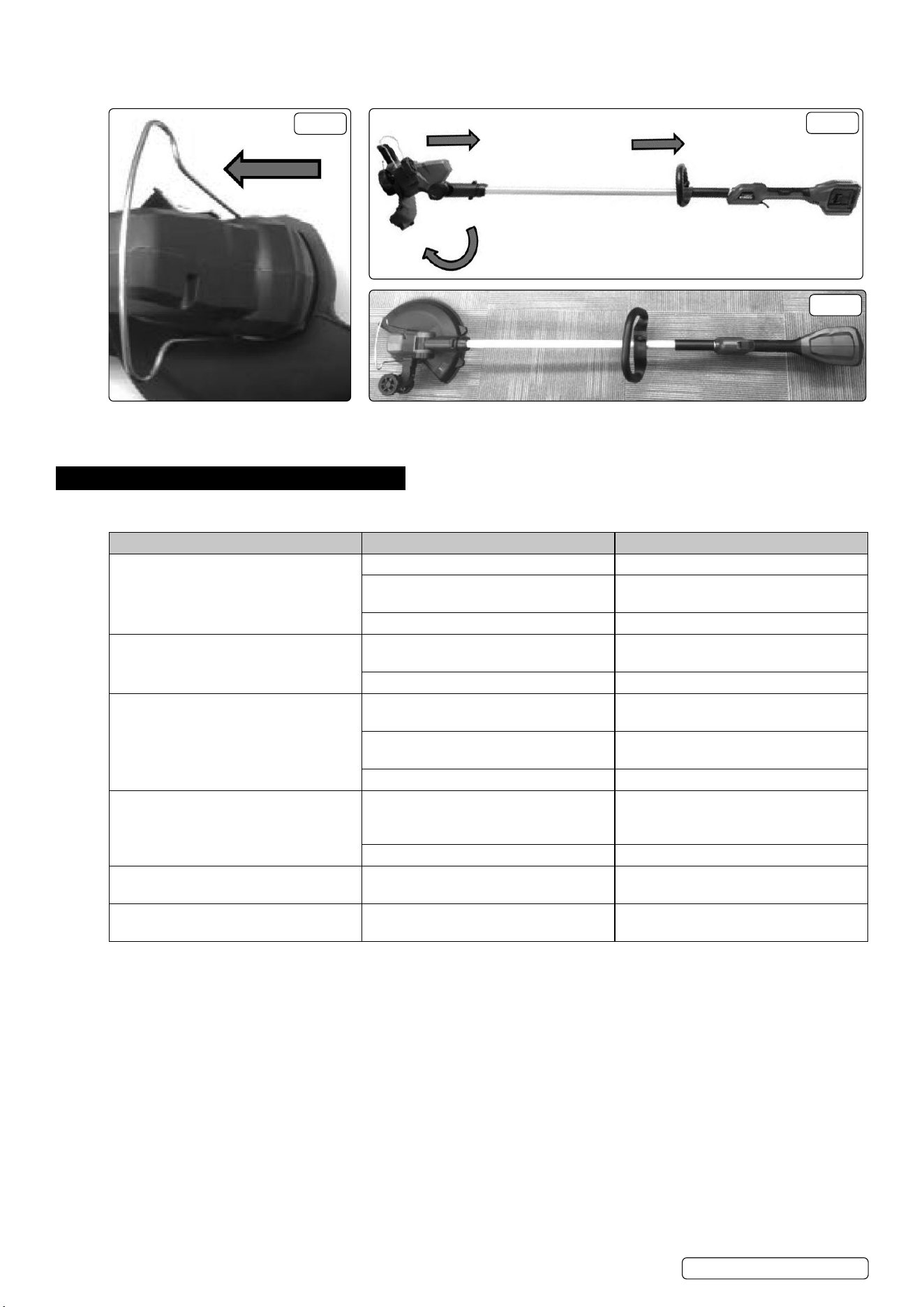
7.2. STORAGE (FIG.39, 40, 41 & 42)
The hook groove in the tool bottom is convenient for hanging the tool from a nail or screw on the wall (g.39). Before storing the tool,
remove the battery cartridge, raise the wire guard, adjust the pivoting head to a right angle.
FIG.40
FIG.41
FIG.42
7.3. CLEANING
Clean the tool by wiping o dust, dirt, or cut o grass with a dry cloth or one dipped in soapy water and wrung out. If the cut o grass is
adhered to the motor housing, be sure to remove it.
8. TROUBLESHOOTING
Before asking for repairs, conduct your own inspection rst. If you nd a problem that is not explained in the manual, do not attempt to
dismantle the tool. Instead, ask a Sealey Authorised Service Centre. Always using Sealey replacement parts for repairs.
PROBLEM POSSIBLE CAUSE SOLUTION
Motor does not run. Battery cartridge not installed. Install the battery cartridge.
Battery problem (under voltage). Recharge the battery. If recharging does
not work, replace the battery.
The drive system does not work correctly. Contact Sealey service centre for repair.
Motor stops running after a little use. Battery’s charge level is low. Recharge the battery. If recharging is not
eective, replace battery.
Overheating. Stop using of tool to allow it to cool down.
It does not reach maximum RPM. Battery is installed improperly. Install the battery cartridge as described in
this manual.
Battery power is dropping. Recharge the battery. If recharging is not
eective, replace battery.
The drive system does not work correctly. Contact Sealey service centre for repair.
Cutting tool does not rotate:
Stop the machine immediately!
Foreign object such as a branch is
jammed between the guard and the nylon
cutting head.
Remove the foreign object.
The drive system does not work correctly. Contact Sealey service centre for repair.
Abnormal vibration:
Stop the machine immediately!
The drive system does not work correctly. Contact Sealey service centre for repair.
Cutting tool and motor does not stop:
Remove the battery immediately!
Electric or electronic malfunction. Remove the battery and contact Sealey
service centre for repair.
CP40VGS Issue 4 12/01/24
Original Language Version
© Jack Sealey Limited

HAND ARM VIBRATION
WARNING! – RISK OF HAND ARM VIBRATION INJURY
This tool may cause Hand Arm Vibration Syndrome if its use is not managed adequately.
This tool is subject to the vibration testing section of the Machinery Directive 2006/42/EC.
This tool is to be operated in accordance with these instructions.
Measured vibration emission value (a): 2.75m/s²
Uncertainty value (k): 1.5m/s²
Please note that the application of the tool to a sole specialist task may produce a dierent average vibration emission. We recommend
that a specic evaluation of the vibration emission is conducted prior to commencing with a specialist task.
A health and safety assessment by the user (or employer) will need to be carried out to determine the suitable duration of use for each tool.
NB: Stated Vibration Emission values are type-test values and are intended to be typical.
Whilst in use, the actual value will vary considerably from and depend on many factors.
Such factors include; the operator, the task and the inserted tool or consumable.
NB: ensure that the length of leader hoses is sucient to allow unrestricted use, as this also helps to reduce vibration.
The state of maintenance of the tool itself is also an important factor, a poorly maintained tool will also increase the risk of Hand Arm
Vibration Syndrome.
HEALTH SURVEILLANCE
We recommend a programme of health surveillance to detect early symptoms of vibration injury so that management procedures can
be modied accordingly.
PERSONAL PROTECTIVE EQUIPMENT
We are not aware of any personal protective equipment (PPE) that provides protection against vibration injury that may result from the
uncontrolled use of this tool. We recommend a sucient supply of clothing (including gloves) to enable the operator to remain warm
and dry and maintain good blood circulation in ngers etc. Please note that the most eective protection is prevention, please refer
to the correct use and maintenance section in these instructions. Guidance relating to the management of hand arm vibration can be
found on the HSE website www.hse.gov.uk - Hand-Arm Vibration at Work.
Sealey Group, Kempson Way, Suffolk Business Park, Bury St Edmunds, Suffolk. IP32 7AR
01284 757500 sales@sealey.co.uk www.sealey.co.uk
Note: It is our policy to continually improve products and as such we reserve the right to alter data, specications and component parts without prior notice.
Important: No Liability is accepted for incorrect use of this product.
Warranty: Guarantee is 12 months from purchase date, proof of which is required for any claim.
ENVIRONMENT PROTECTION
Recycle unwanted materials instead of disposing of them as waste. All tools, accessories and packaging should be
sorted, taken to a recycling centre and disposed of in a manner which is compatible with the environment. When
the product becomes completely unserviceable and requires disposal, drain any uids (if applicable) into approved
containers and dispose of the product and uids according to local regulations.
REGISTER YOUR
PURCHASE HERE
WEEE REGULATIONS
Dispose of this product at the end of its working life in compliance with the EU Directive on Waste Electrical and Electronic
Equipment (WEEE). When the product is no longer required, it must be disposed of in an environmentally protective way. Contact
your local solid waste authority for recycling information.
BATTERY REMOVAL
Under the Waste Batteries and Accumulators Regulations 2009, Jack Sealey Ltd are required to inform potential purchasers of products
containing batteries (as defined within these regulations), that they are registered with Valpak’s registered compliance scheme. Jack
Sealey Ltd Batteries Producer Registration Number (BPRN) is BPRN00705.
CP40VGS Issue 4 12/01/24
Original Language Version
© Jack Sealey Limited
