Loading ...
Loading ...
Loading ...
Monitor - Power Quality Monitoring
Introduction16
16-3
The momentary rms voltage is constantly monitored by the Analyzer. It calculates an
average from these measuring values across 10-minute observation periods. The 10-
minute averages are compared against the tolerance range (in this example 102 ... 138 V).
The 100 % limit means that the 10-minute averages must always (i.e. 100 % of time or
with 100 % probability) be within range. The bar graph will turn to red if a 10-minute
average crosses the tolerance range.
The adjustable limit of for instance 95 % (i.e. 95 % probability) means that 95 % of the
10-minute averages must be within tolerance. The 95 % limit is less stringent than the
100 % limit. Therefore the related tolerance range usually is tighter. For 120 V this for
instance can be + or – 10 % (a tolerance range between 108 ... 132 V).
The bars for Dips/Interruptions/Rapid Voltage Changes/Swells are narrow and indicate
the number of limits violations that occurred during the observation period. The allowed
number is adjustable (for instance to 20 Dips/week). The bar turns to red if the adjusted
limit is violated.
You can use a pre-defined set of limits or define your own. The pre-defined set is that
according to the EN50160 standard. You can define your own set of limits and save it in
memory under a user-definable file name. As a basis for this set you can use EN50160 or
any other set. Refer to Chapter 24 Paragraph Limits Adjustments for a description.
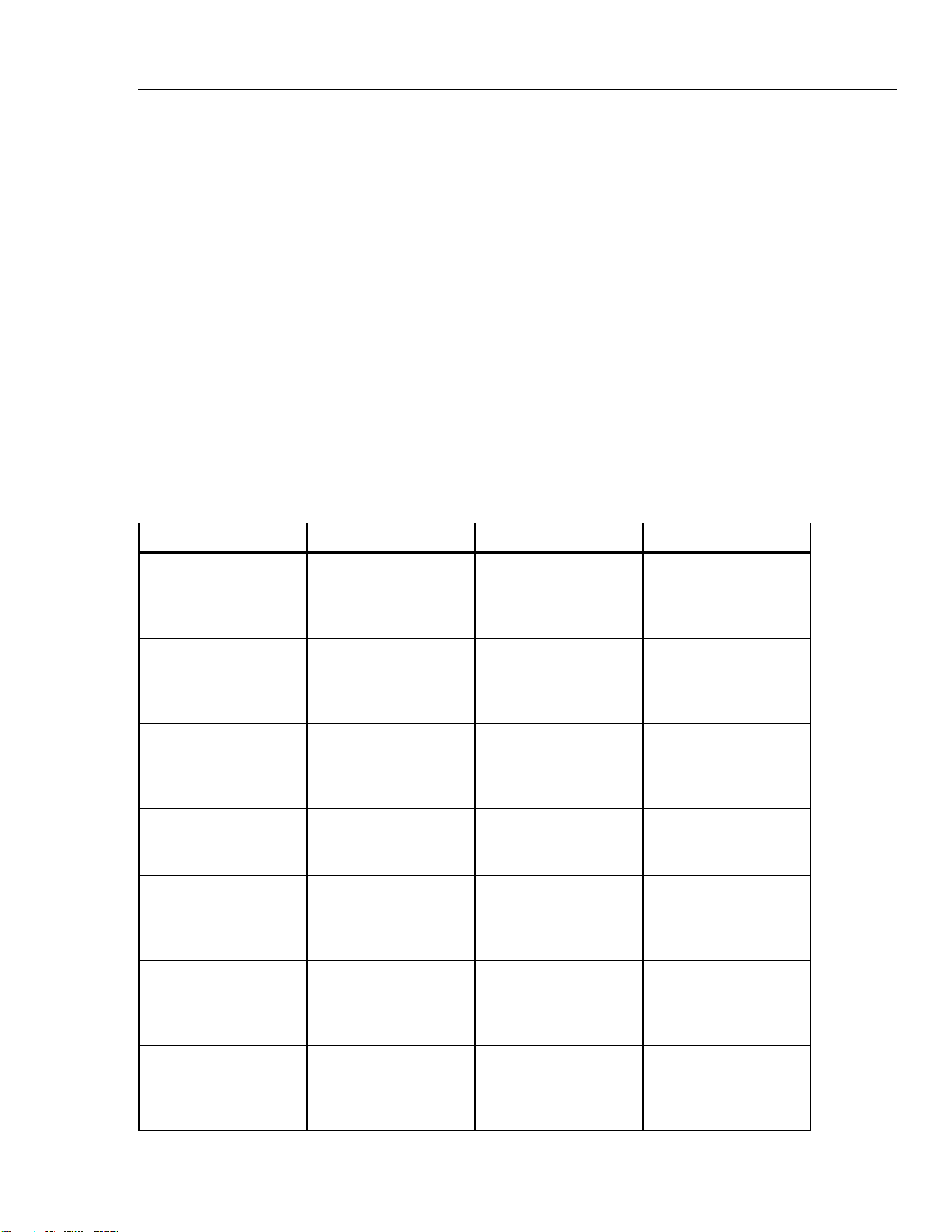
The table below gives a survey of the aspects of Power Quality Monitoring:
Parameter Available Bar Graphs Limits Averaging Interval
Vrms 3, one for each phase Probability 100 %: upper
& lower limit
Probability x %: upper &
lower limit
10 minutes
Harmonics 3, one for each phase Probability 100 %: upper
limit
Probability x %: upper
limit
10 minutes
Flicker 3, one for each phase Probability 100 %: upper
limit
Probability x %: upper
limit
2 Hrs.
Dips/Interruptions/Rapid
Voltage Changes/Swells
4, one for each
parameter covering all 3
phases
allowed number of
events per week
½ cycle rms based
Unbalance 1, covering all 3 phases Probability 100 %: upper
limit
Probability x %: upper
limit
10 minutes
Frequency 1, covering all 3 phases
Measured on Reference
Voltage Input A/L1
* Probability 100 %:
upper & lower limit
Probability x %:
upper & lower limit
10 sec.
Mains Signaling 6, one for each phase,
for freq 1 and freq 2
* Probability 100 %
upper limit: N/A
Probability x %:
upper limit: adjustable
3 sec. rms
1.888.610.7664 sales@GlobalTestSupply.com
Fluke-Direct.com
Loading ...
Loading ...
Loading ...