Please give us a chance to make it right and do better !
Contact our friendly customer service department for help first.
Replacements for missing or damaged parts will be shipped ASAP !
Contact Us !
Do NOT return this item.
US:cs.us@costway.com
UK:cs.uk@costway.com
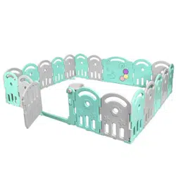
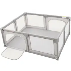
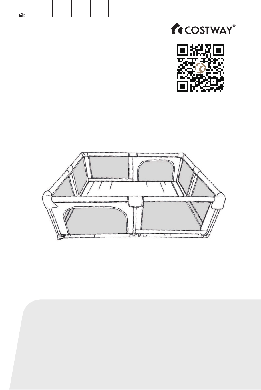
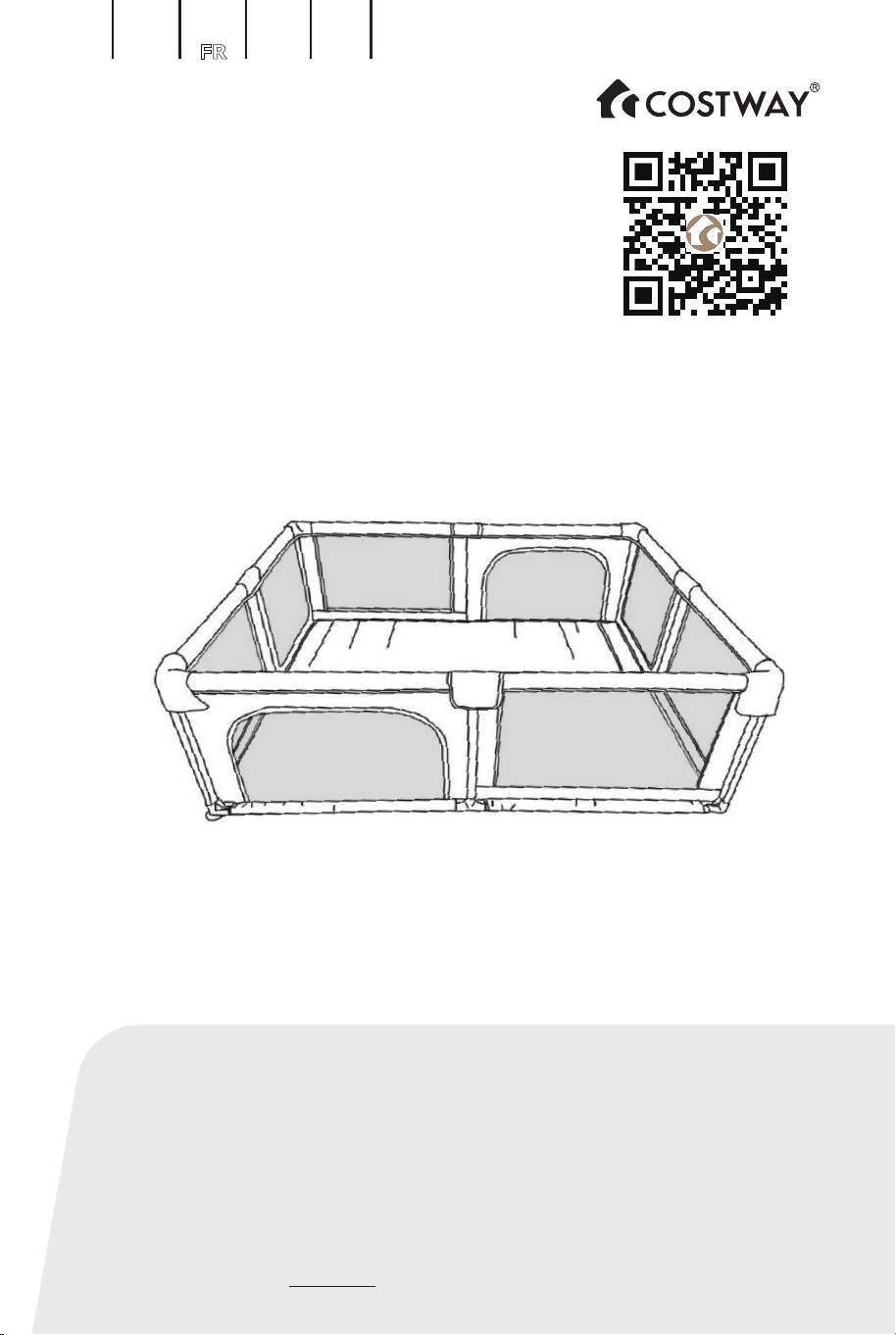
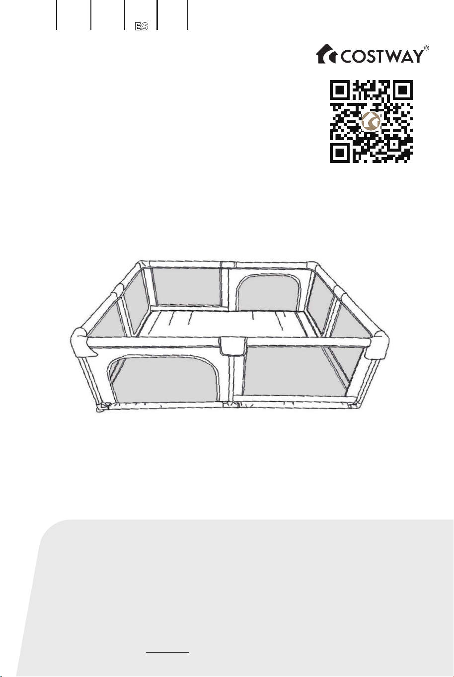
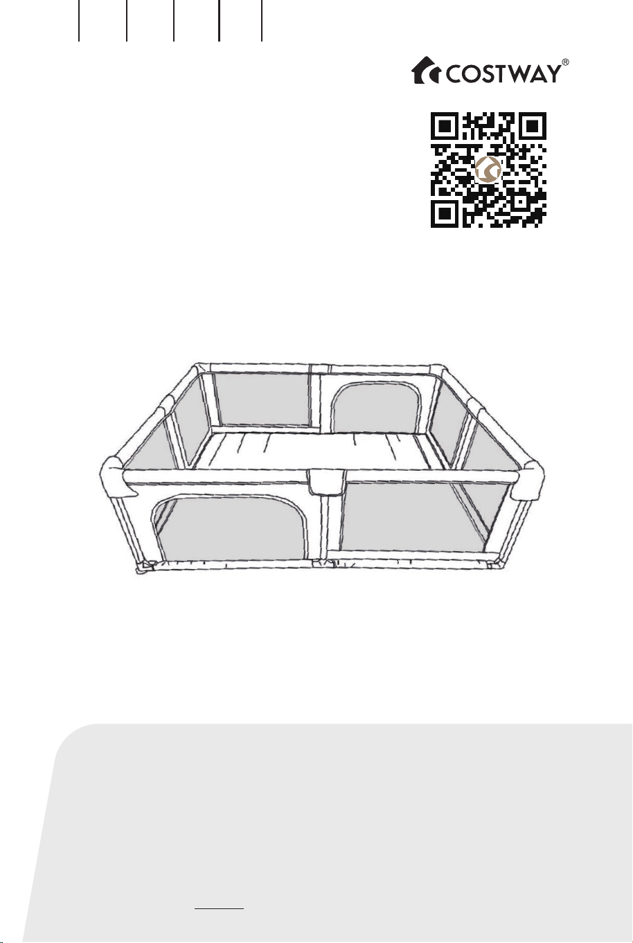
Baby Playpen
BB5560
USER’S MANUAL
THIS INSTRUCTION BOOKLET CONTAINS IMPORTANT SAFETY INFORMATION. PLEASE READ AND KEEP FOR FUTURE REFERENCE.
EN DE FR ES IT PL
Scan QR code for
assembly instructions

02 03
EN
Before You Start
General Warnings:
Danger! Keep all small parts and packaging materials for this product away from
babies and children, otherwise they may pose a choking hazard.
The product must be installed and used under the supervision of an adult.
Read through each step carefully and follow the proper order.
Remove all Packaging, separate and count all parts and hardware before
installation.
Please ensure that all parts are correctly installed, incorrect installation can lead to
a danger.
We recommend that, where possible, all items are assembled near the area in
which they will be placed in use, to avoid moving the product unnecessarily once
assembled.
Ensure a secure surface during installation, and place the product always on a flat,
steady and stable surface.
Please read all instructions carefully and keep it for future reference.
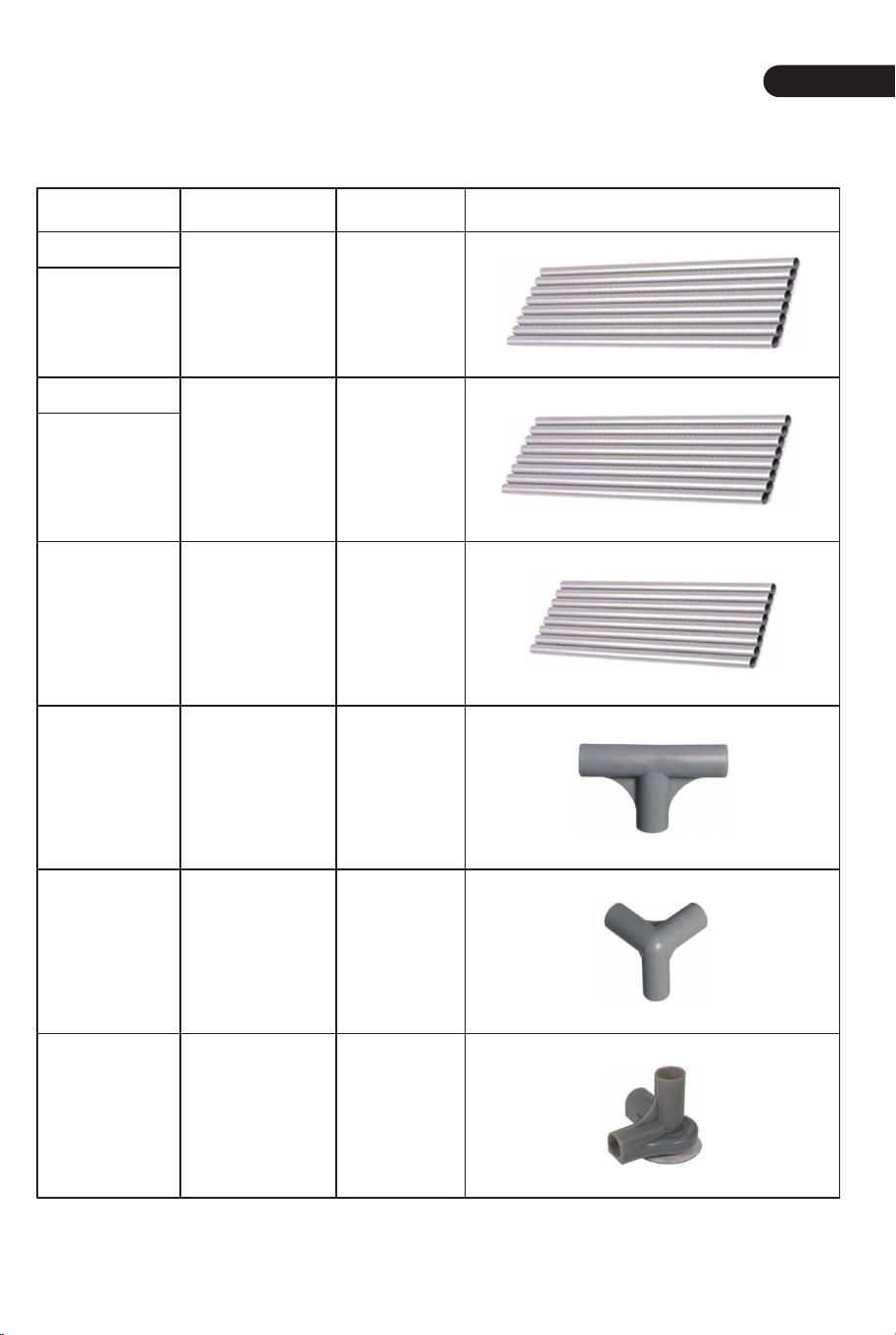
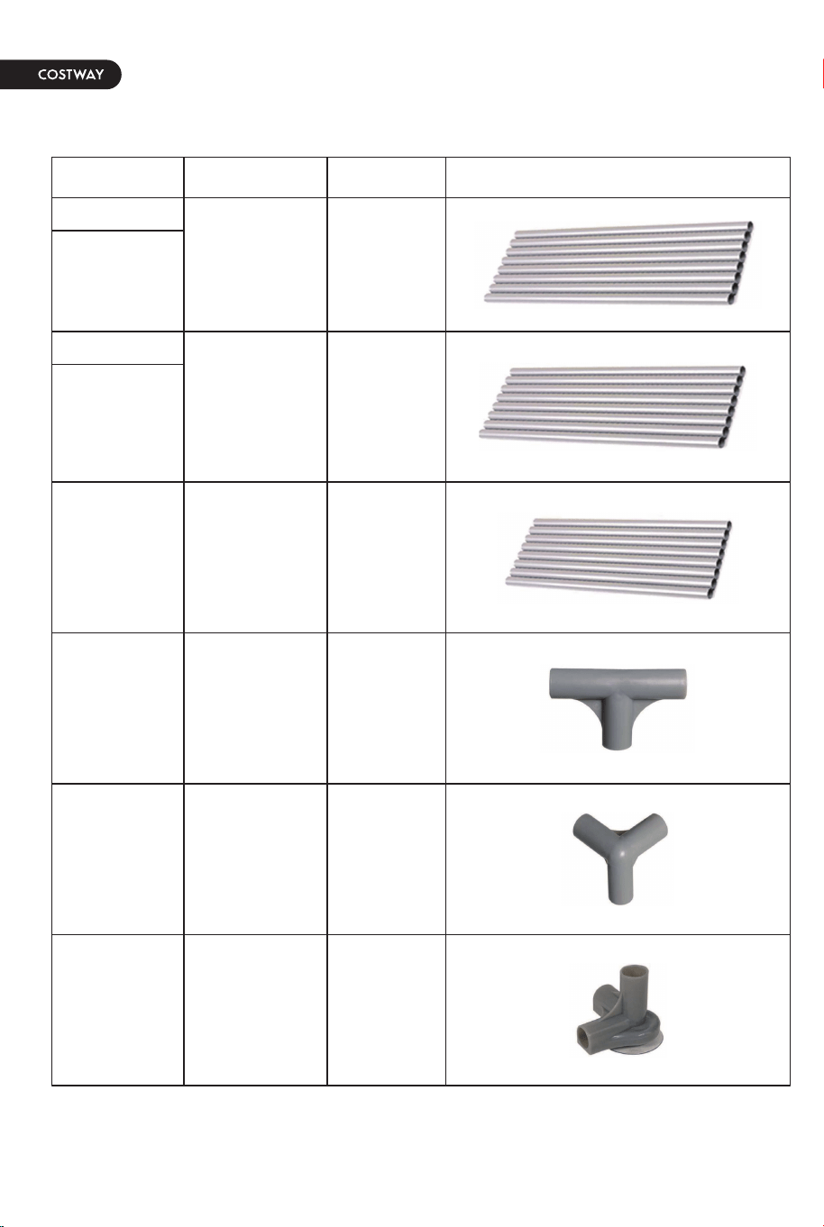
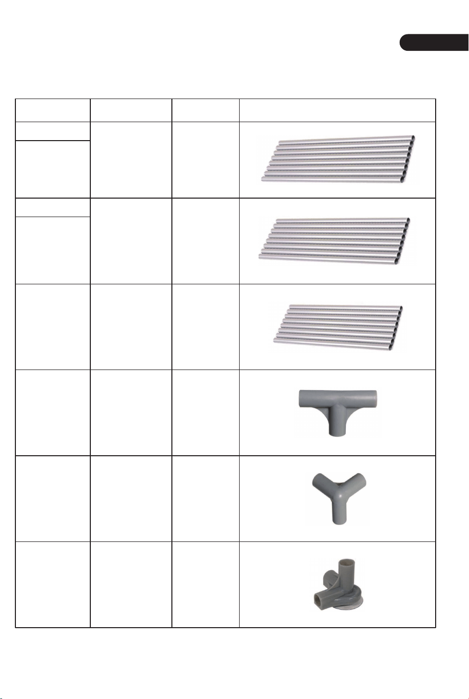
Parts List In The Box
Name
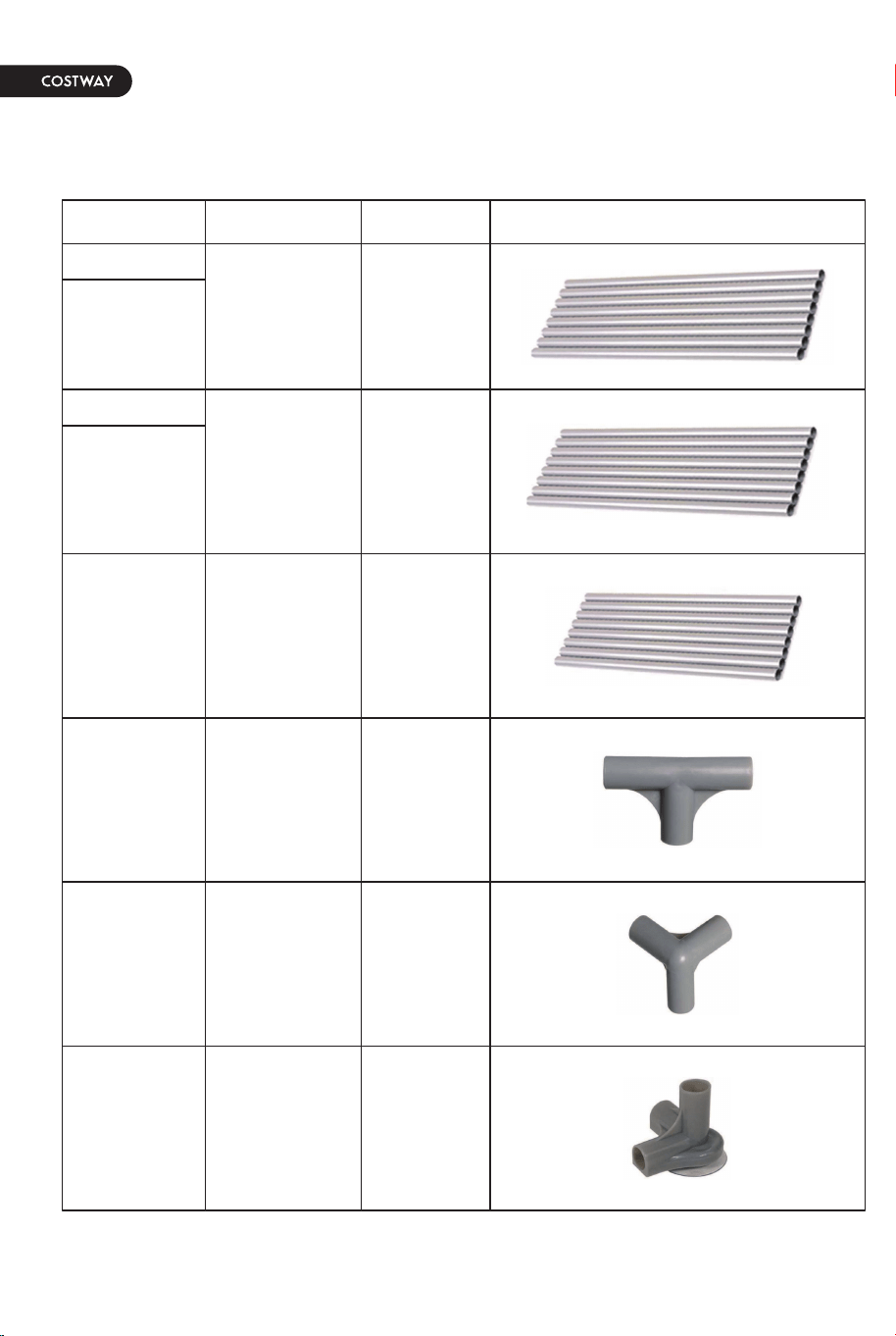
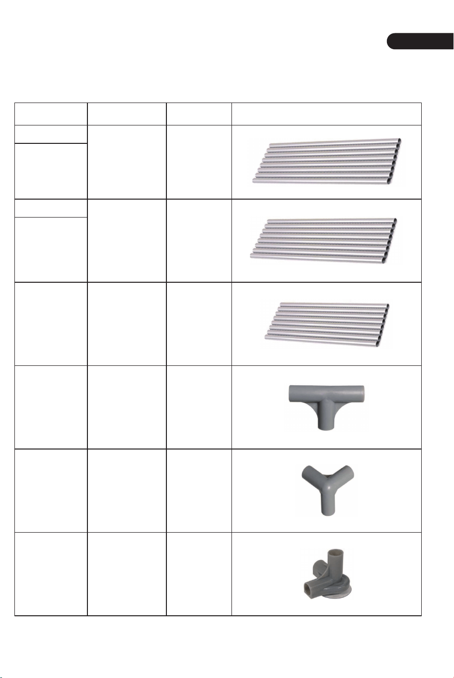
Upper Pipe
Lower Pipe
Upper Pipe
Lower Pipe
Upright
Column
Pipe
917
717
639
8
8
8
8
4
4
T-type Joint
Joint
Suction
Cup Joint
Length (mm) Quantity Figure
Long Side
Short Side
02 03
EN
Before You Start
General Warnings:
Danger! Keep all small parts and packaging materials for this product away from
babies and children, otherwise they may pose a choking hazard.
The product must be installed and used under the supervision of an adult.
Read through each step carefully and follow the proper order.
Remove all Packaging, separate and count all parts and hardware before
installation.
Please ensure that all parts are correctly installed, incorrect installation can lead to
a danger.
We recommend that, where possible, all items are assembled near the area in
which they will be placed in use, to avoid moving the product unnecessarily once
assembled.
Ensure a secure surface during installation, and place the product always on a flat,
steady and stable surface.
Please read all instructions carefully and keep it for future reference.
Parts List In The Box
Name
Upper Pipe
Lower Pipe
Upper Pipe
Lower Pipe
Upright
Column
Pipe
917
717
639
8
8
8
8
4
4
T-type Joint
Joint
Suction
Cup Joint
Length (mm) Quantity Figure
Long Side
Short Side
04
EN
05
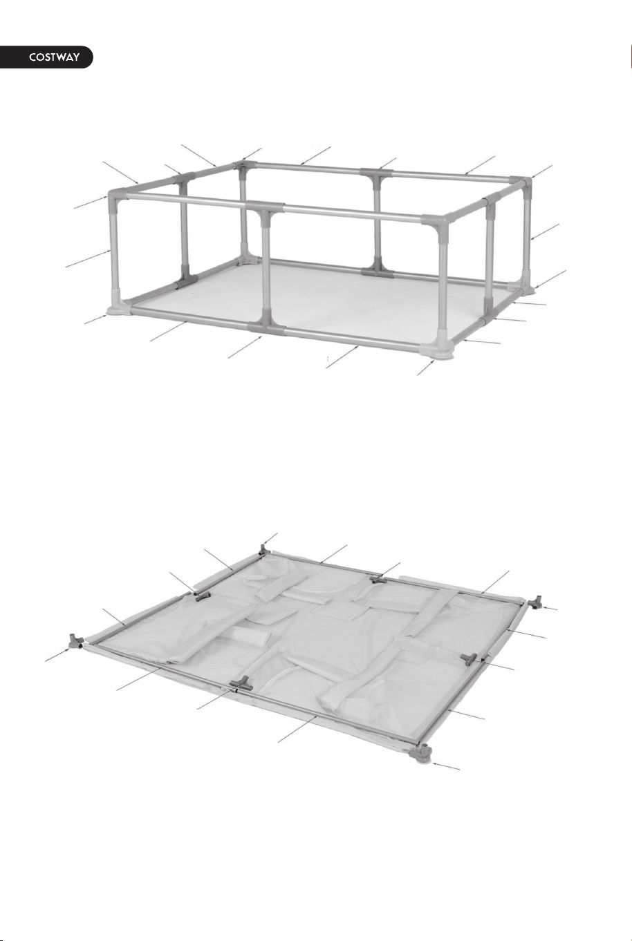
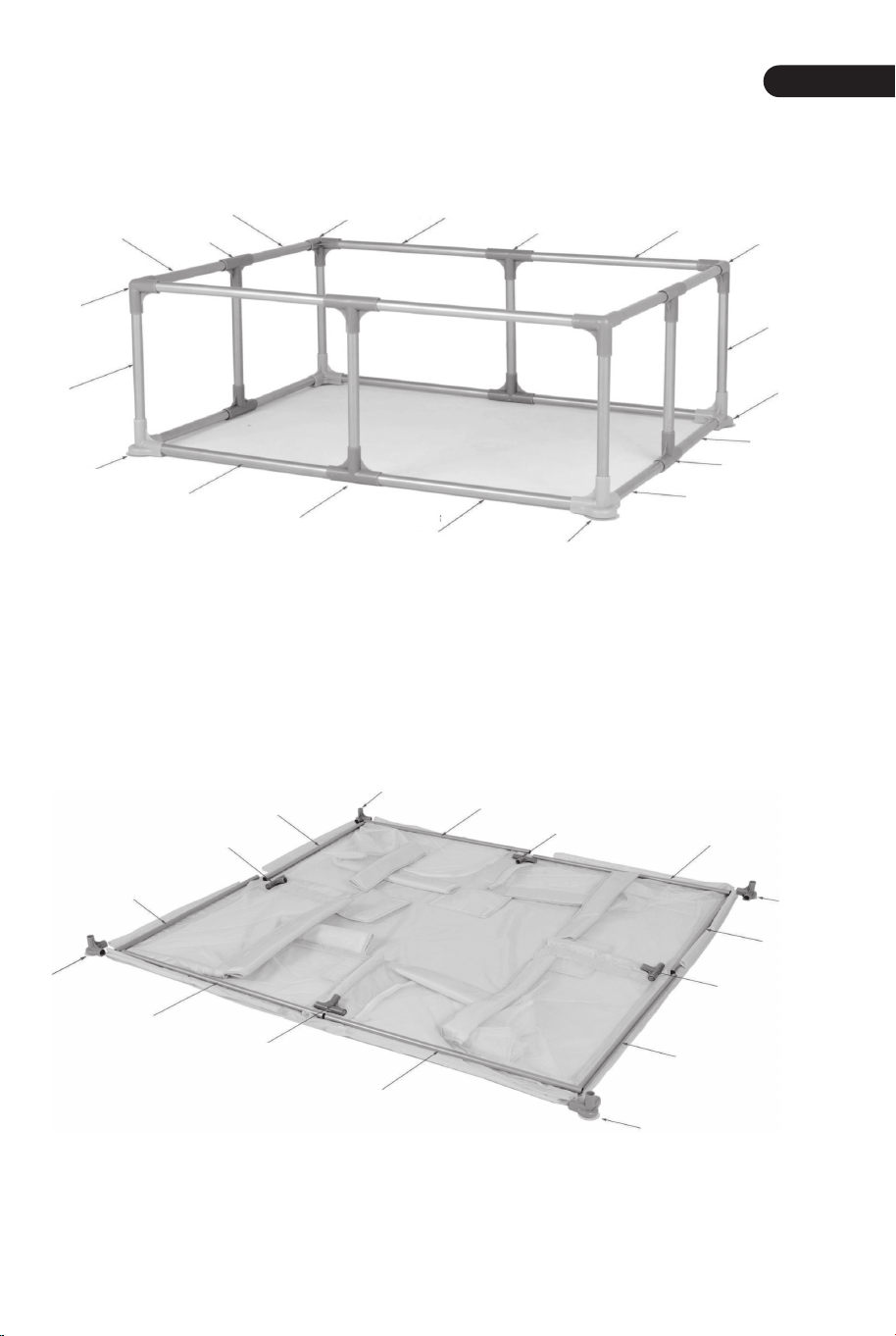
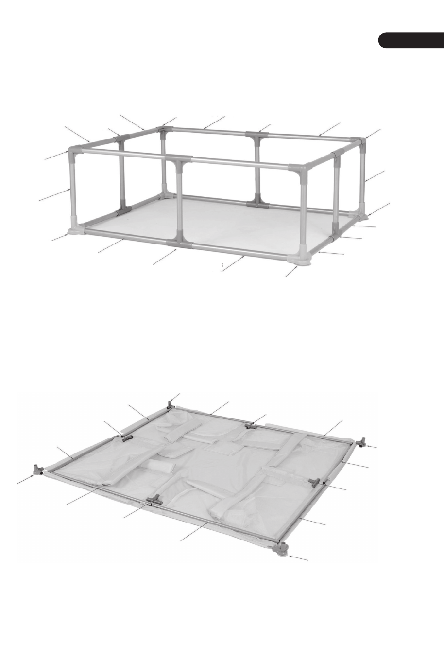
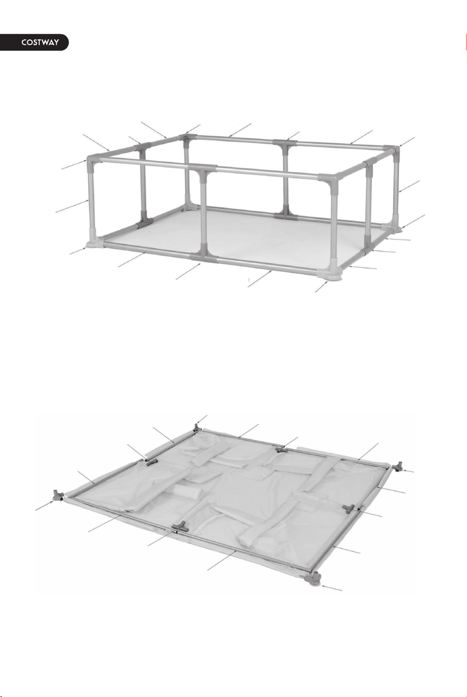
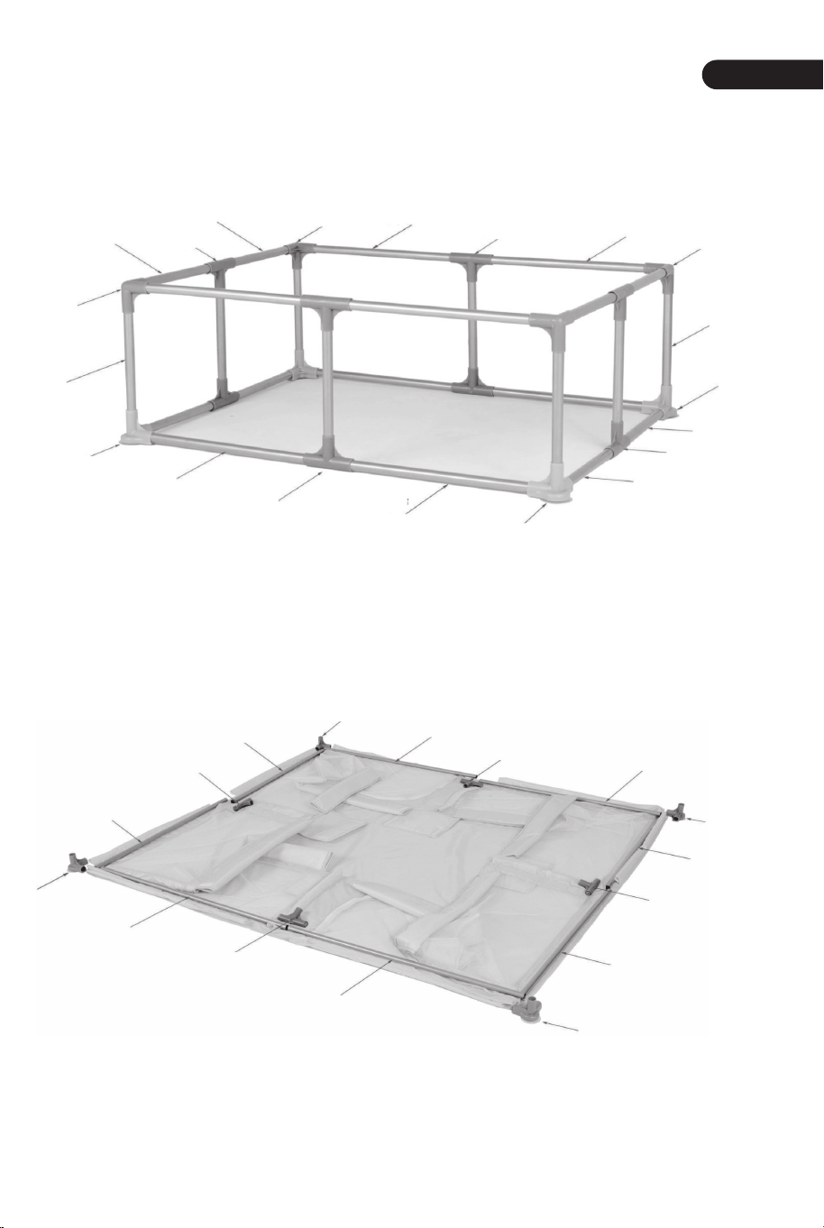
Parts Location Diagram
Installation Steps
Step 1
717mm
T-type Joint
Three-way
Joint
Three-way
Joint
Three-way
Joint
T-type Joint
T-type Joint
T-type Joint
717mm
717mm
717mm
917mm
917mm
917mm
917mm
639mm
639mm
Suction Cup
Joint
Suction Cup
Joint
Suction Cup
Joint
717mm
717mm
717mm
717mm
T-type Joint
T-type Joint
T-type Joint
T-type Joint
917mm
917mm
917mm
917mm
Suction Cup
Joint
Suction Cup
Joint
Suction Cup
Joint
Suction Cup
Joint
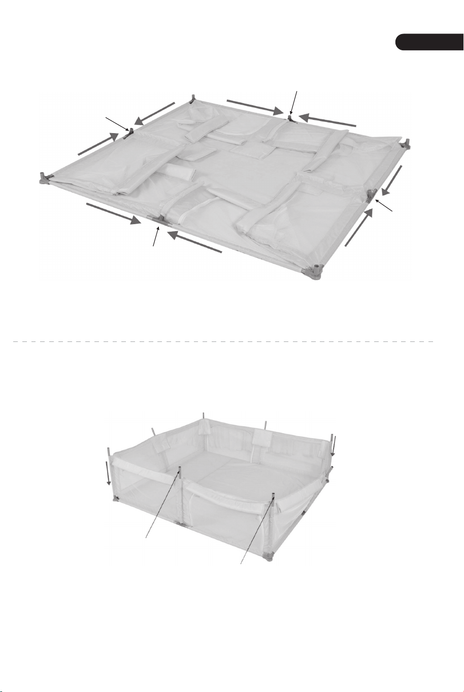
As shown in the figure, place 4 lower pipes (917mm) and 4 lower pipes (717mm) around
the cloth cover, then put 4 T-type joints in the middle, and 4 suction cup joints at the four
corners of the cloth cover.
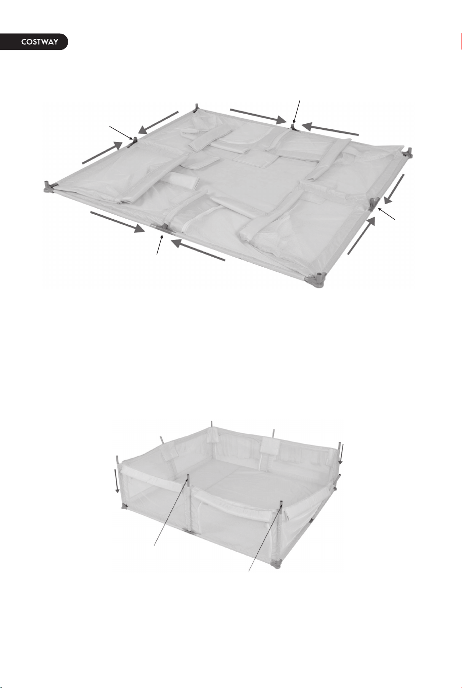
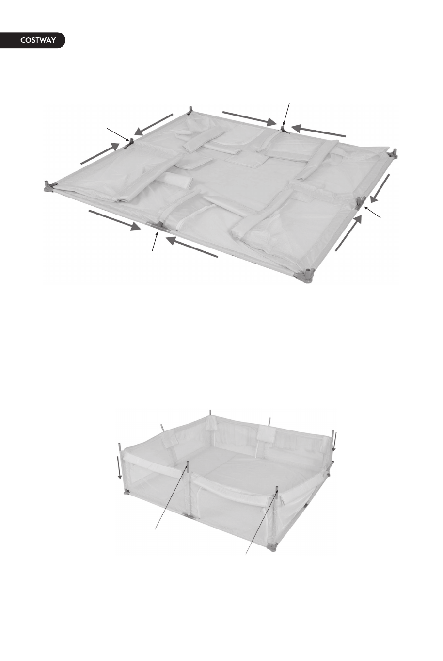
Use 8 upright column pipes(639mm) to pass through the cloth cover first, and install them
on the three-way joints and suction cup joints in the direction indicated by the red arrow.
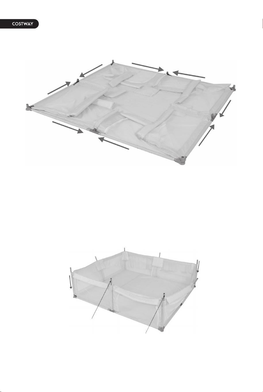
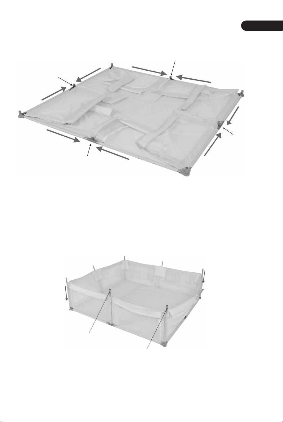
Step 2
Step 3
T-type Joint
T-type Joint
T-type Joint
T-type Joint
639mm
639mm
639mm
639mm
639mm
639mm
639mm
639mm
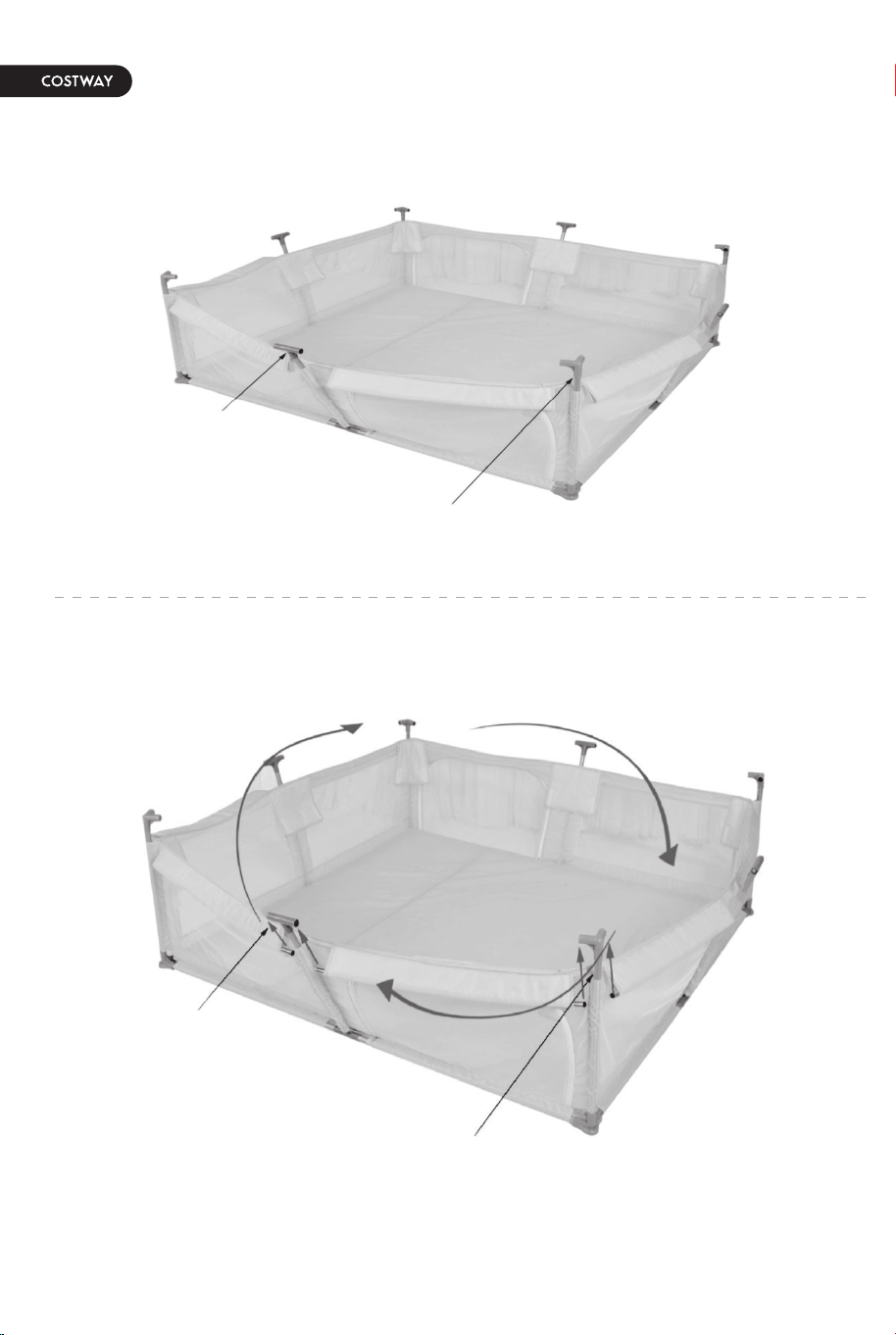
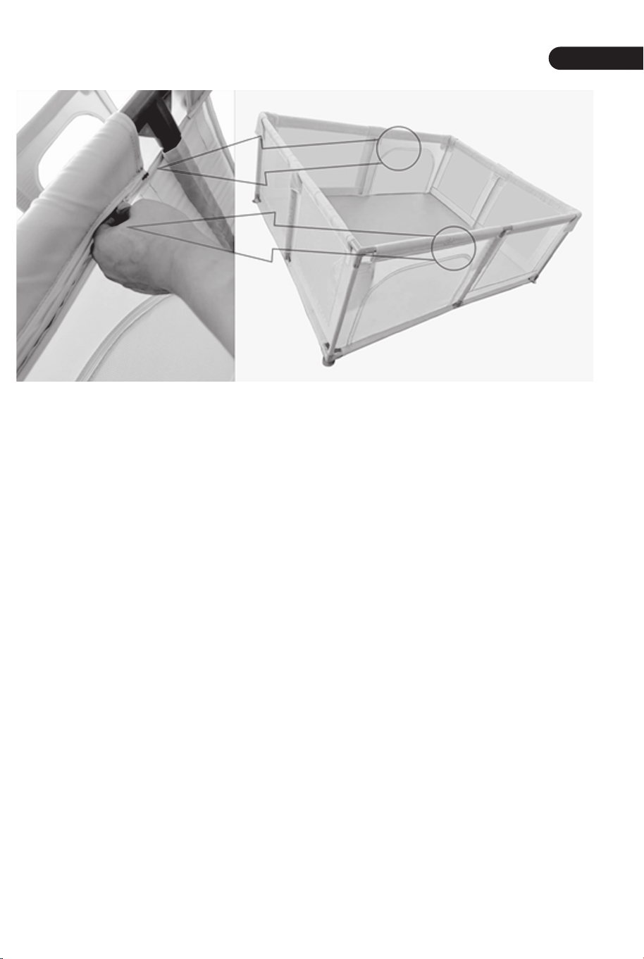
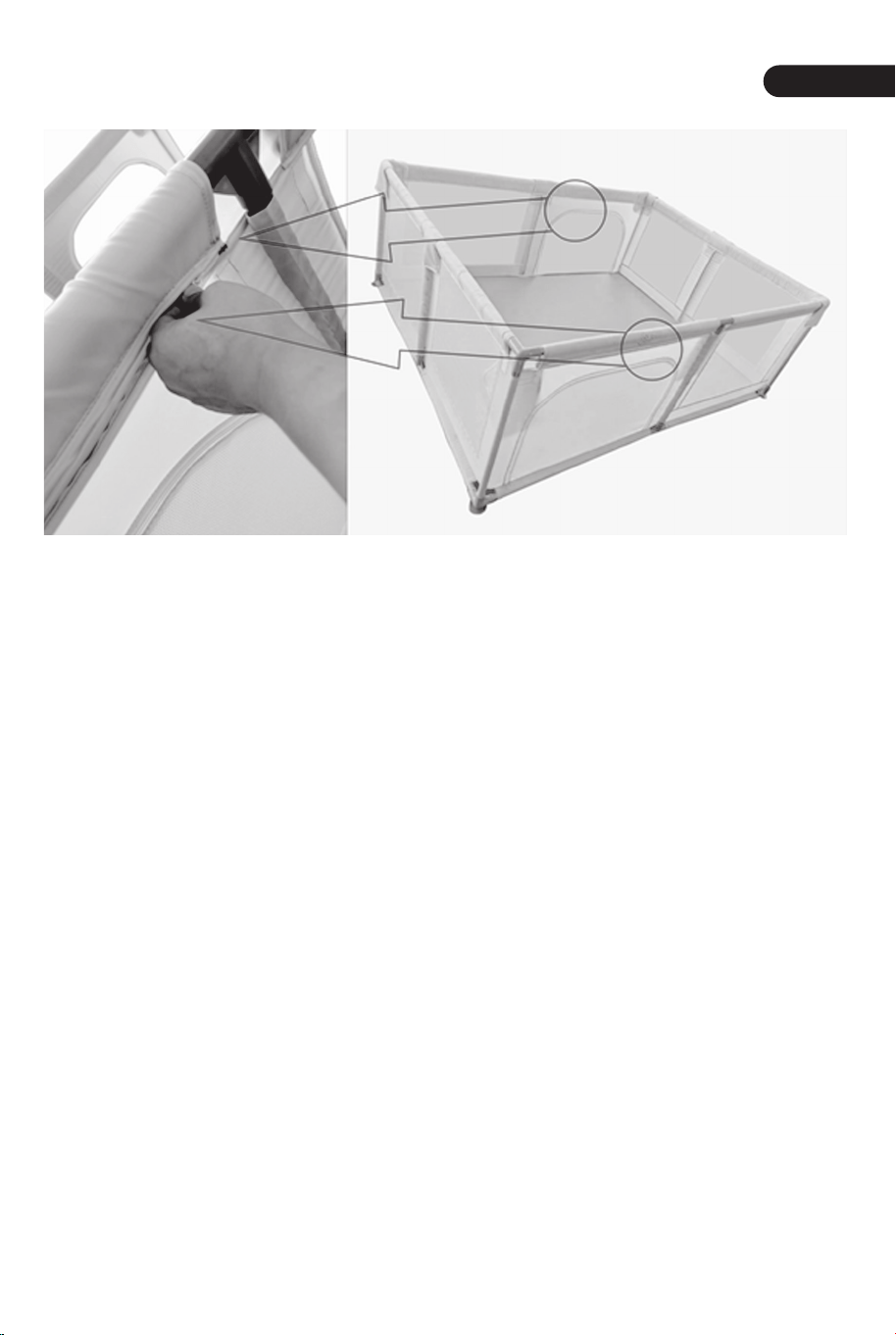
Note: Start from the middle and then both sides.
The lower pipes are fully inserted into the cloth cover, connected to the T-type The lower
pipes are fully inserted into the cloth cover, connected to the T-type corners.
04
EN
05
Parts Location Diagram
Installation Steps
Step 1
717mm
T-type Joint
Three-way
Joint
Three-way
Joint
Three-way
Joint
T-type Joint
T-type Joint
T-type Joint
717mm
717mm
717mm
917mm
917mm
917mm
917mm
639mm
639mm
Suction Cup
Joint
Suction Cup
Joint
Suction Cup
Joint
717mm
717mm
717mm
717mm
T-type Joint
T-type Joint
T-type Joint
T-type Joint
917mm
917mm
917mm
917mm
Suction Cup
Joint
Suction Cup
Joint
Suction Cup
Joint
Suction Cup
Joint
As shown in the figure, place 4 lower pipes (917mm) and 4 lower pipes (717mm) around
the cloth cover, then put 4 T-type joints in the middle, and 4 suction cup joints at the four
corners of the cloth cover.
Use 8 upright column pipes(639mm) to pass through the cloth cover first, and install them
on the three-way joints and suction cup joints in the direction indicated by the red arrow.
Step 2
Step 3
T-type Joint
T-type Joint
T-type Joint
T-type Joint
639mm
639mm
639mm
639mm
639mm
639mm
639mm
639mm
Note: Start from the middle and then both sides.
The lower pipes are fully inserted into the cloth cover, connected to the T-type The lower
pipes are fully inserted into the cloth cover, connected to the T-type corners.
06
EN
07
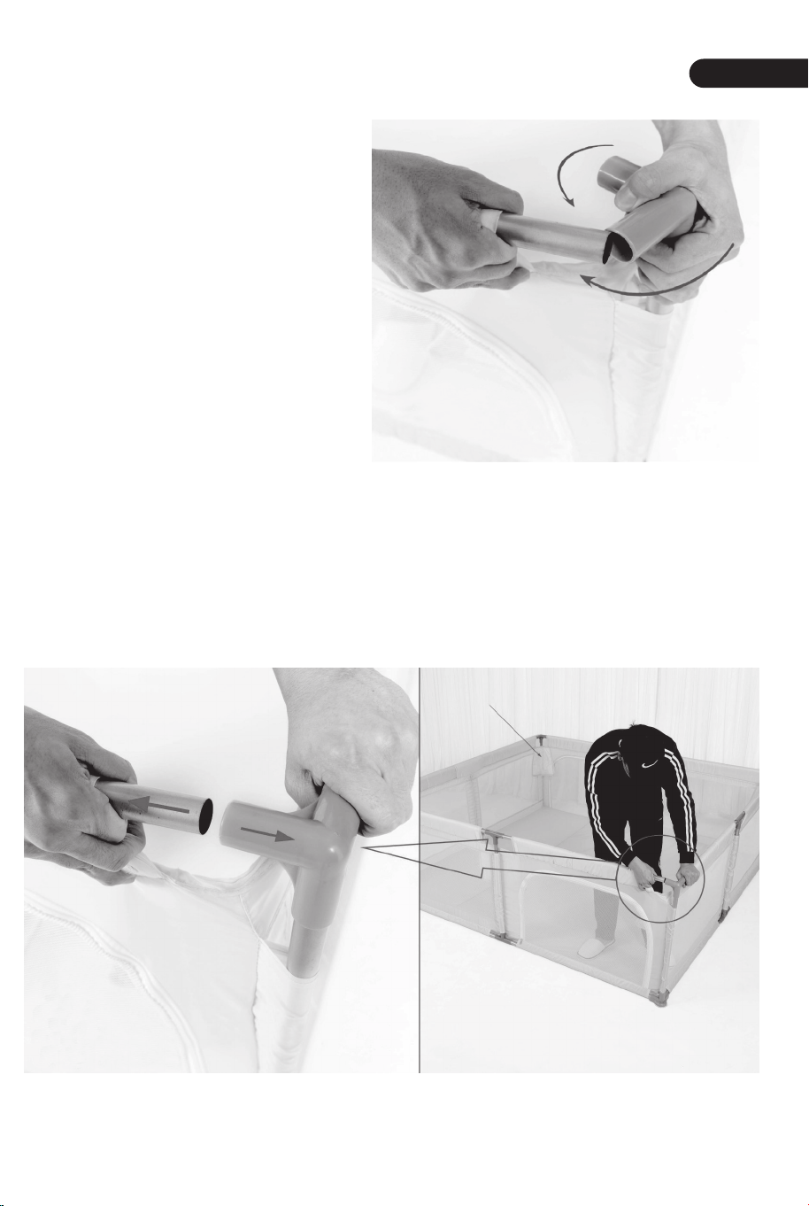
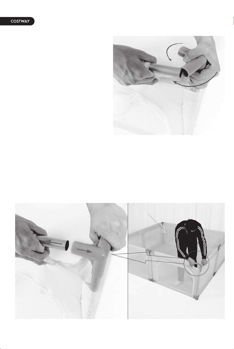
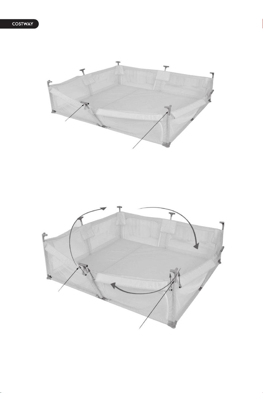
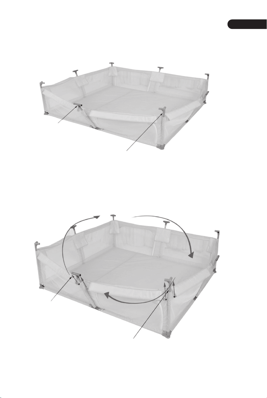
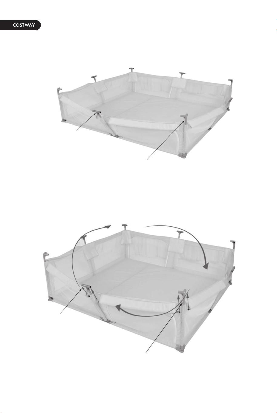
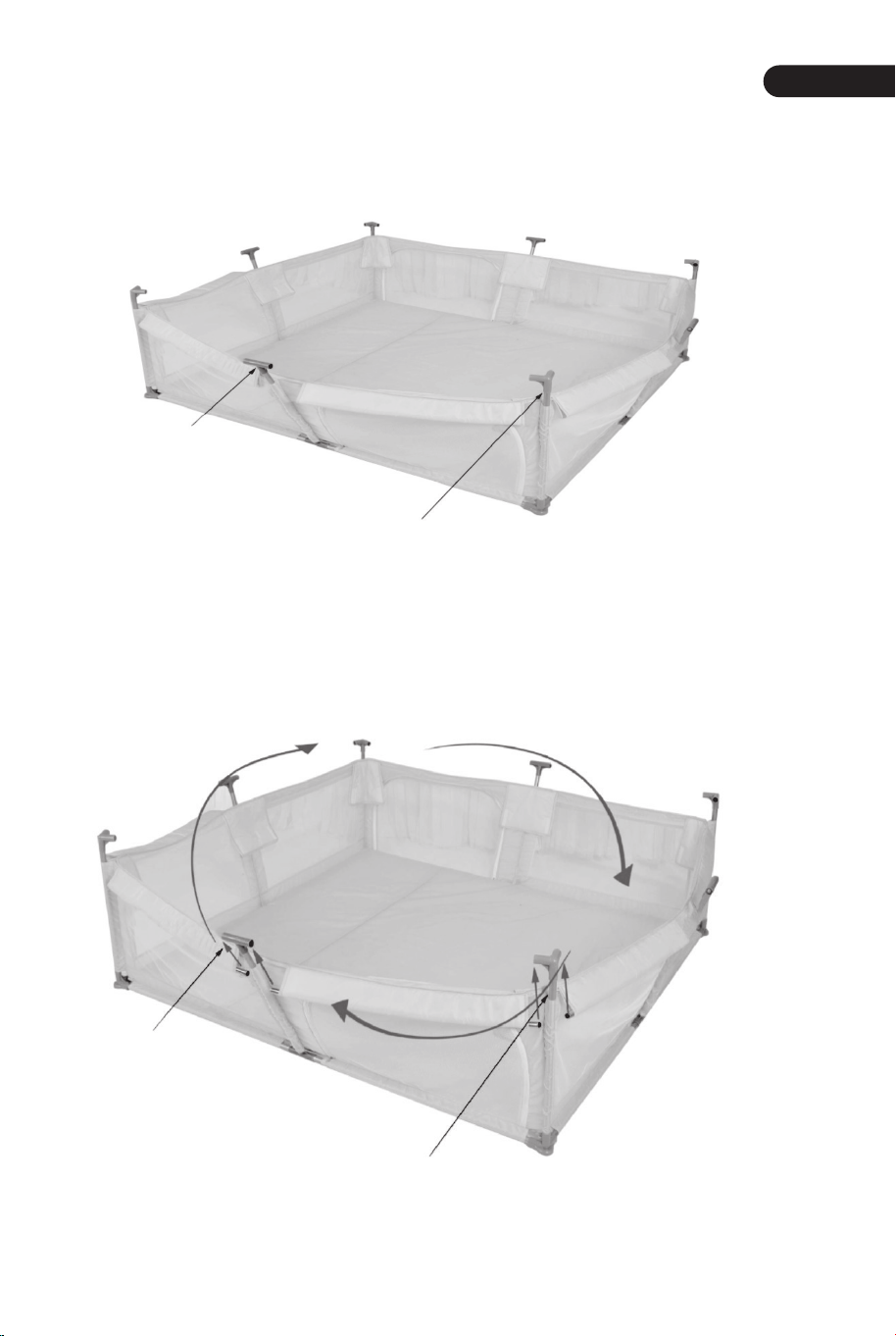
The upper pipes are fully inserted into the cloth cover as shown by the red arrow. Connect
the plastic three-way joints in a clockwise direction.
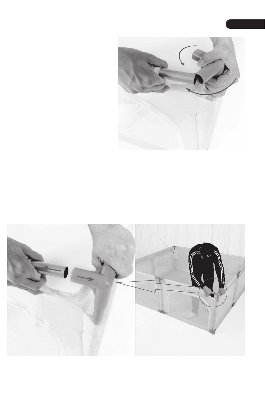
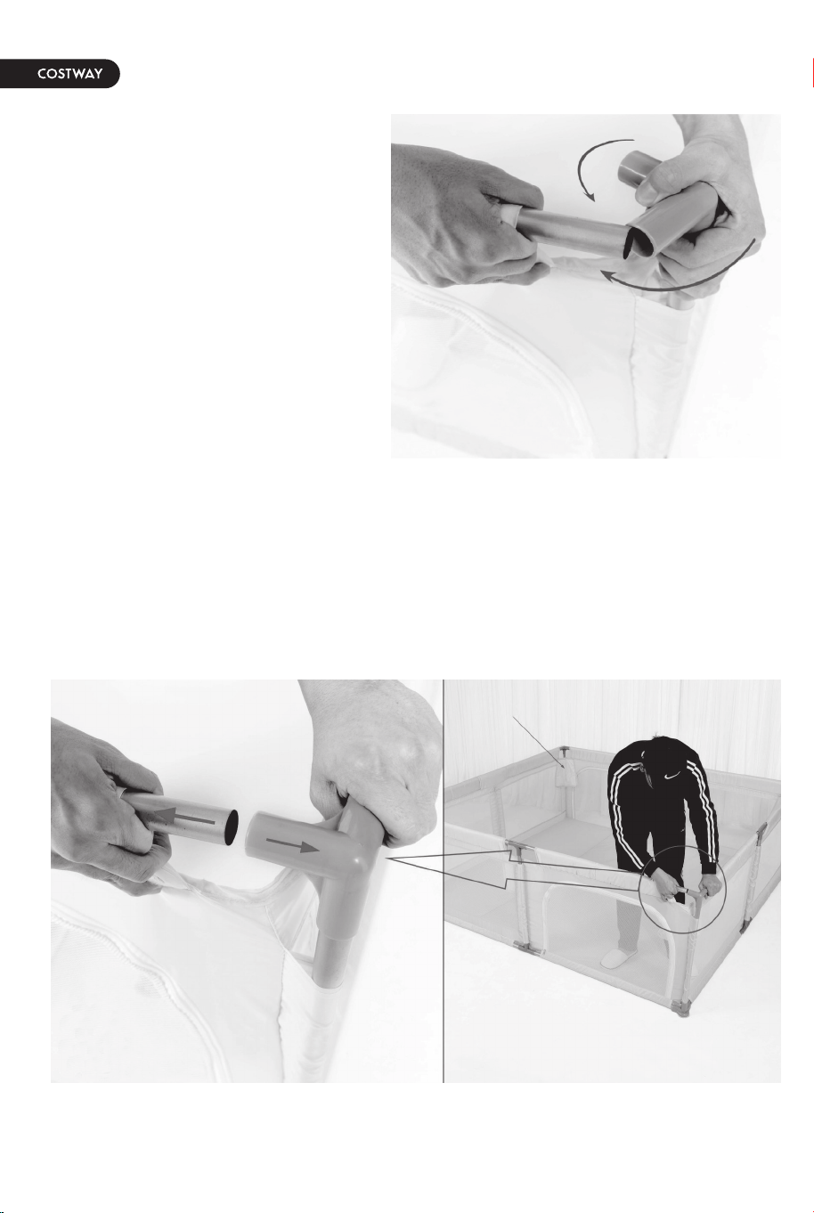
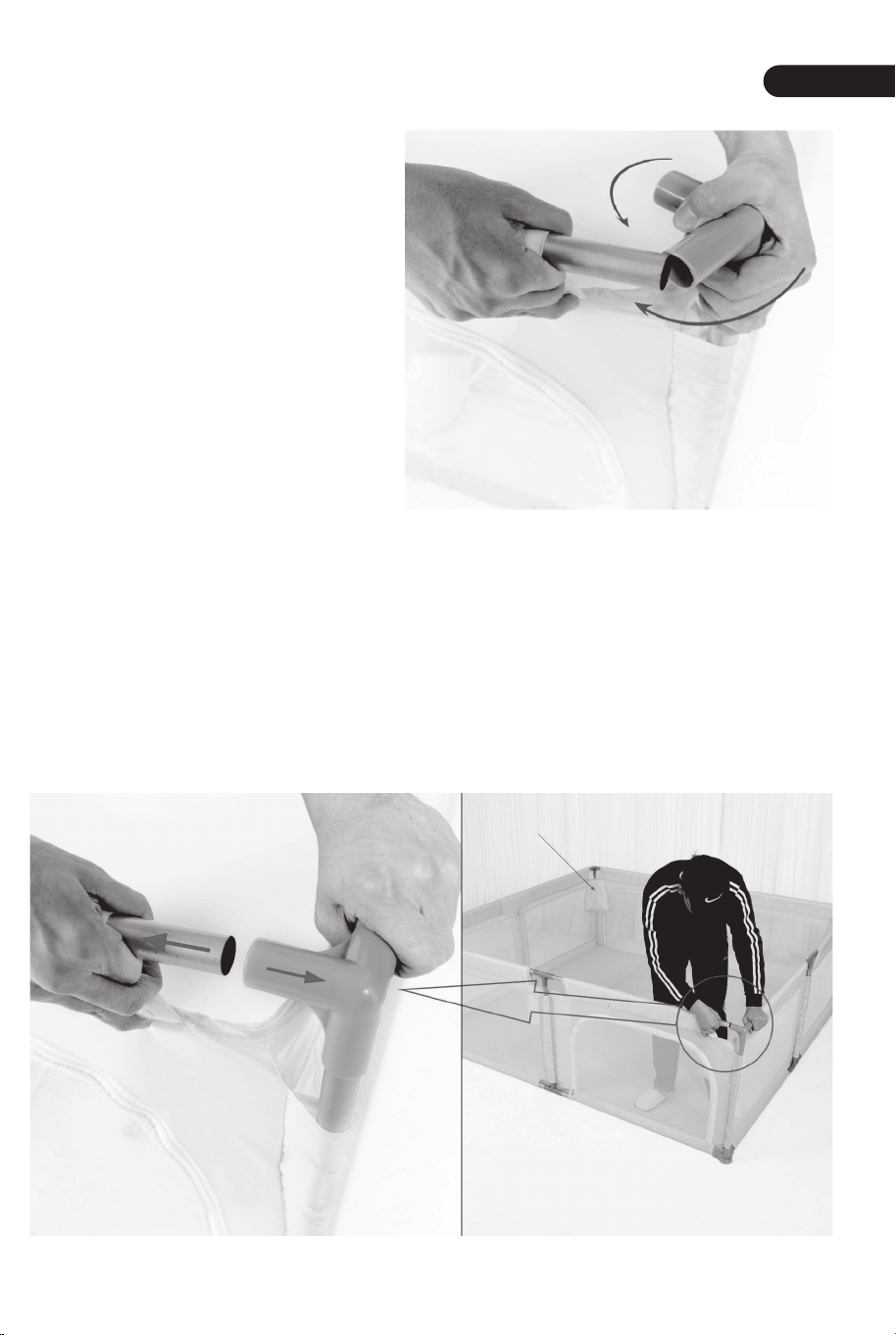
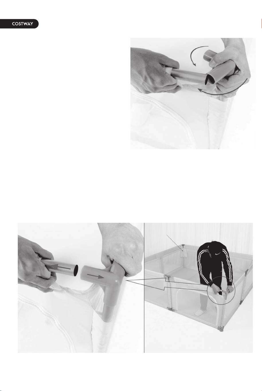
As shown in the figure, rotate the
three-way joint by 50° in the direction
of the blue arrow to align with the steel
pipe, and then turn it by 50° in the
direction of the red arrow to fit into the
steel pipe.
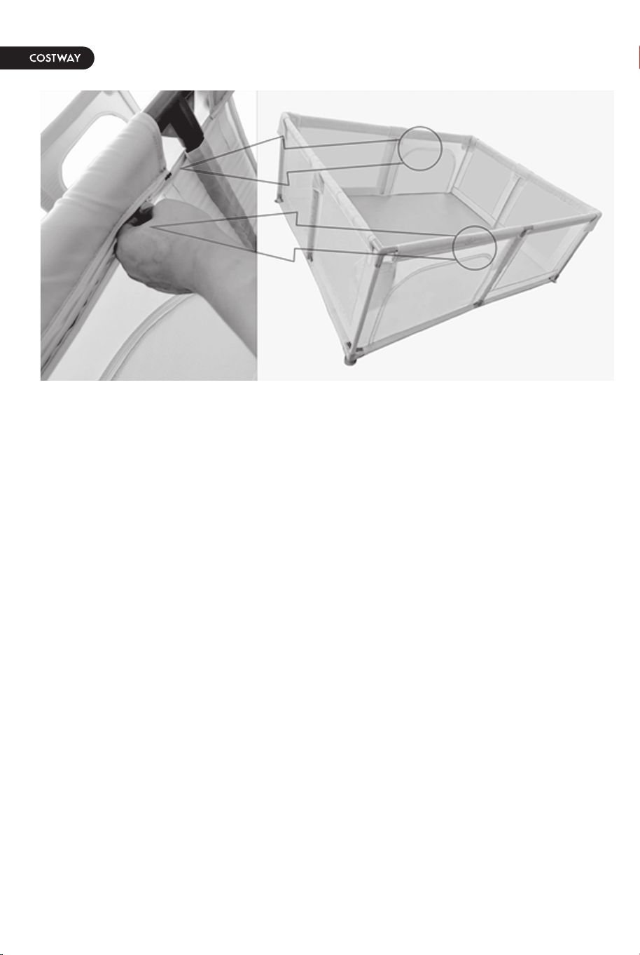
As shown in the figure, push the three-way joint forward in the direction of the red arrow,
pull the steel pipe backwards, aligned with the three-way joint to insert the steel pipe.
Install T-type Joints and three-way joints on the upright column pipes.
Step 4
Step 5
Three-way Joint
T-type Joint
T-type Joint
T-type Joint
T-type Joint
Three-way Joint
Three-way Joint
Three-way Joint
Three-way Joint
Three-way Joint
Three-way Joint
Three-way Joint
T-type Joint
T-type Joint
T-type Joint
T-type Joint
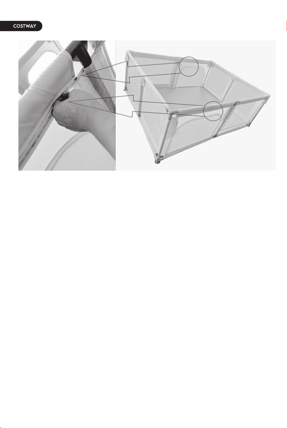
Tips for connecting
three-way joints
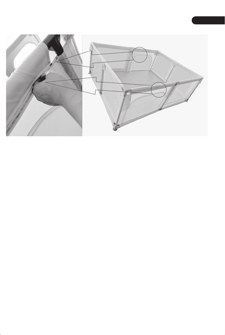
Last step installation tips
Cover Piece
06
EN
07
The upper pipes are fully inserted into the cloth cover as shown by the red arrow. Connect
the plastic three-way joints in a clockwise direction.
As shown in the figure, rotate the
three-way joint by 50° in the direction
of the blue arrow to align with the steel
pipe, and then turn it by 50° in the
direction of the red arrow to fit into the
steel pipe.
As shown in the figure, push the three-way joint forward in the direction of the red arrow,
pull the steel pipe backwards, aligned with the three-way joint to insert the steel pipe.
Install T-type Joints and three-way joints on the upright column pipes.
Step 4
Step 5
Three-way Joint
T-type Joint
T-type Joint
T-type Joint
T-type Joint
Three-way Joint
Three-way Joint
Three-way Joint
Three-way Joint
Three-way Joint
Three-way Joint
Three-way Joint
T-type Joint
T-type Joint
T-type Joint
T-type Joint
Tips for connecting
three-way joints
Last step installation tips
Cover Piece
08
Close the cover piece and zip up to complete the assembly.
Bitte wenden Sie sich bei weiteren Fragen an unseren Kundenservice
Ersatzteile können so schnell wie möglich geliefert werden.
Deutsches Büro: FDS GmbH, Neuer Höltigbaum 36, 22143 Hamburg, Deutschland
Kontaktieren Sie uns !
Schicken Sie diesen Artikel NICHT zurück,
bitte wenden Sie sich an unseren Kundenservice.
Deutsches Büro: FDS GmbH, Neuer Höltigbaum 36, 22143 Hamburg, Deutschland
Laufstall
BB5560
HANDBUCH
DIESE ANLEITUNG ENTHÄLT WICHTIGE SICHERHEITSINFORMATIONEN. BITTE SORGFÄLTIG LESEN UND ZUM SPÄTEREN NACHSCHLAGEN AUFBEWAHREN.
EN DE FR ES IT PL
Bevor Sie beginnen
Hinweis zur Montage
Achtung! Halten Sie alle kleinteile und Verpackungsmaterialien fern von Babys und
Kindern, ansonsten besteht Erstickungsgefahr.
Der Artikel muss unter der Aufsicht eines Erwachsenen montiert und benutzt
werden.
Lesen Sie jeden Schritt sorgfältig durch und befolgen Sie die richtige Reihenfolge.
Entfernen Sie alle Verpackungen, Überprüfen Sie, ob alle Teile und Zubehörteile
vorhanden sind.
Bitte stellen Sie sicher, dass alle Teile richtig montiert sind, eine falsche Montage
kann zu einer Gefahr führen.
Wir empfehlen, alle Teile möglichst in der Nähe des Aufstellungsortes zu
montieren, um unnötige Bewegungen nach der Montage zu vermeiden.
Achten Sie bei der Montage auf einen sicheren Untergrund und stellen Sie den
Artikel immer auf eine ebene, feste und stabile Fläche.
Bitte sorgfältig lesen und zum späteren Nachschlagen aufbewahren.
11
Scan QR code for
assembly instructions
Legen Sie, wie in der Abbildung gezeigt, 4 untere Rohre (917 mm) und 4 untere Rohre (717
mm) um die Stoffabdeckung, legen Sie dann 4 T-stück Verbinder in die Mitte und 4
Dreiwegeverbindung mit Saugnapf an die vier Ecken des Stoffes Startseite.
12
DE
13
Teileliste in der Box
Name
Oberes Rohr
Unteres Rohr
Oberes Rohr
Oberes Rohr
Lange Seite
Kurze Seite
Aufrechtes
Säulenrohr
917
717
639
8
8
8
8
4
4
T-stück
Verbinder
Länge (mm) Menge Bild
Dreiwegever
bindung
Dreiwegever
bindung mit
Saugnapf
Diagramm für die Position der Teile
Installationsschritte
Schritt 1
717mm
T-stück
Verbinder
T-stück
Verbinder
T-stück
Verbinder
T-stück Verbinder
717mm
717mm
717mm
917mm
917mm
917mm
917mm
639mm
639mm
Dreiwegeverb
indung
Dreiwegeverb
indung mit
Saugnapf
Dreiwegeverb
indung mit
Saugnapf
Dreiwegeverb
indung mit
Saugnapf
Dreiwegeverb
indung
Dreiwegeverb
indung
717mm
717mm
717mm
717mm
917mm
917mm
917mm
917mm
Dreiwegeverb
indung mit
Saugnapf
Dreiwegeverb
indung mit
Saugnapf
Dreiwegeverb
indung mit
Saugnapf
Dreiwegeverb
indung mit
Saugnapf
T-stück
Verbinder
T-stück
Verbinder
T-stück
Verbinder
T-stück
Verbinder
14
DE
15
Hinweis: Beginnen Sie in der Mitte und dann auf beiden Seiten. Die unteren Rohre sind
vollständig in die Stoffabdeckung eingeführt und mit dem T-stück Verbinder verbunden, wie
durch den roten Pfeil dargestellt. Dann installieren Sie den Dreiwegeverbindung mit
Saugnapf an den vier Ecken.
Installieren Sie T-stück Verbinder und Dreiwegeverbindung an den aufrechten Säulenrohren.
Die oberen Rohre werden vollständig in die Stoffabdeckung eingeführt, wie durch den roten
Pfeil dargestellt. Verbinden Sie den Kunststoff Dreiwegeverbindung im Uhrzeigersinn.
Führen Sie zuerst 8 aufrecht stehende Säulenrohre (639 mm) durch die Stoffabdeckung und
installieren Sie sie in der durch den roten Pfeil angegebenen Richtung am
Dreiwegeverbindung und Dreiwegeverbindung mit Saugnapf.
Schritt 2
Schritt 3
T-stück
Verbinder
T-stück
Verbinder
T-stück
Verbinder
T-stück
Verbinder
639mm
639mm
639mm
639mm
639mm
639mm
639mm
639mm
Schritt 4
Schritt 5
T-stück
Verbinder
T-stück
Verbinder
T-stück
Verbinder
T-stück
Verbinder
Dreiwegeverb
indung
Dreiwegeverb
indung
Dreiwegeverb
indung
Dreiwegeverb
indung
T-stück
Verbinder
T-stück
Verbinder
T-stück
Verbinder
T-stück
Verbinder
Dreiwegeverb
indung
Dreiwegeverb
indung
Dreiwegeverb
indung
Dreiwegeverb
indung
Drehen Sie die Dreiwegeverbindung wie
in der Abbildung gezeigt um 50° in
Richtung des blauen Pfeils, um sie am
Stahlrohr auszurichten, und drehen Sie
sie dann um 50° in Richtung des roten
Pfeils, damit sie in das Stahlrohr passt.
Schieben Sie wie in der Abbildung gezeigt die Dreiwegeverbindung in Richtung des roten
Pfeils nach vorne, ziehen Sie das Stahlrohr nach hinten und richten Sie es an der
Dreiwegeverbindung aus, um das Stahlrohr einzuführen.
Setzen Sie die Abdeckstück auf und schließen Sie sie mit einem Reißverschluss,um die
Montage abzuschließen.
Tipps zum
Anschluss von
Dreiwegeverbindung
Tipps zur letzten Installationschritt
Abdeckstück
16
DE
17

VEUILLEZ NOUS DONNER L’OCCASION DE L’AMÉLIORER !
Contactez notre service à la clientèle pour obtenir de l’aide.
Les remplacements de pièces manquantes ou endommagées seront
expédiés dès que possible !
Contactez-nous !
Ne retournez pas cet article.
FR : [email protected]
Parc pour Bébé
BB5560
MANUEL DE L’UTILISATEUR
Contactez notre service à la clientèle pour obtenir de l’aide.
EN DE FR ES IT PL
CE MANUEL CONTIENT DES INFORMATIONS IMPORTANTES SUR LA SÉCURITÉ. VEUILLEZ LE LIRE ET LE CONSERVER POUR TOUTE RÉFÉRENCE FUTURE.
Scan QR code for
assembly instructions

20 21
Avant de Commencer
Avertissements Généraux :
Danger ! Éloignez toutes les petites pièces et le matériel d’emballage des bébés et
des enfants pour éviter un risque d’étouffement.
Le produit doit être installé et utilisé sous la surveillance d’un adulte.
Lisez attentivement chaque étape et suivez le bon ordre.
Retirez tous les emballages, séparez et comptez toutes les pièces et le matériel
avant l’installation.
Assurez-vous que toutes les pièces soient correctement installées. Une installation
incorrecte peut entraîner un danger.
Assurez une surface sûre pendant l’assemblage et placez le produit toujours sur
une surface plane et stable.
Veuillez lire attentivement toutes les instructions et les conserver pour la référence
ultérieure.
FR
Liste des pièces dans la boîte
Nom
Pipe
supérieure
Pipe
inférieure
Pipe
supérieure
Pipe
inférieure
Côté long
Côté court
Tuyau à
colonne
verticale
917
717
639
8
8
8
8
4
4
Joint en T
Longueur (mm) Qté. Image
Joint à trois
voies
Joint à
ventouse
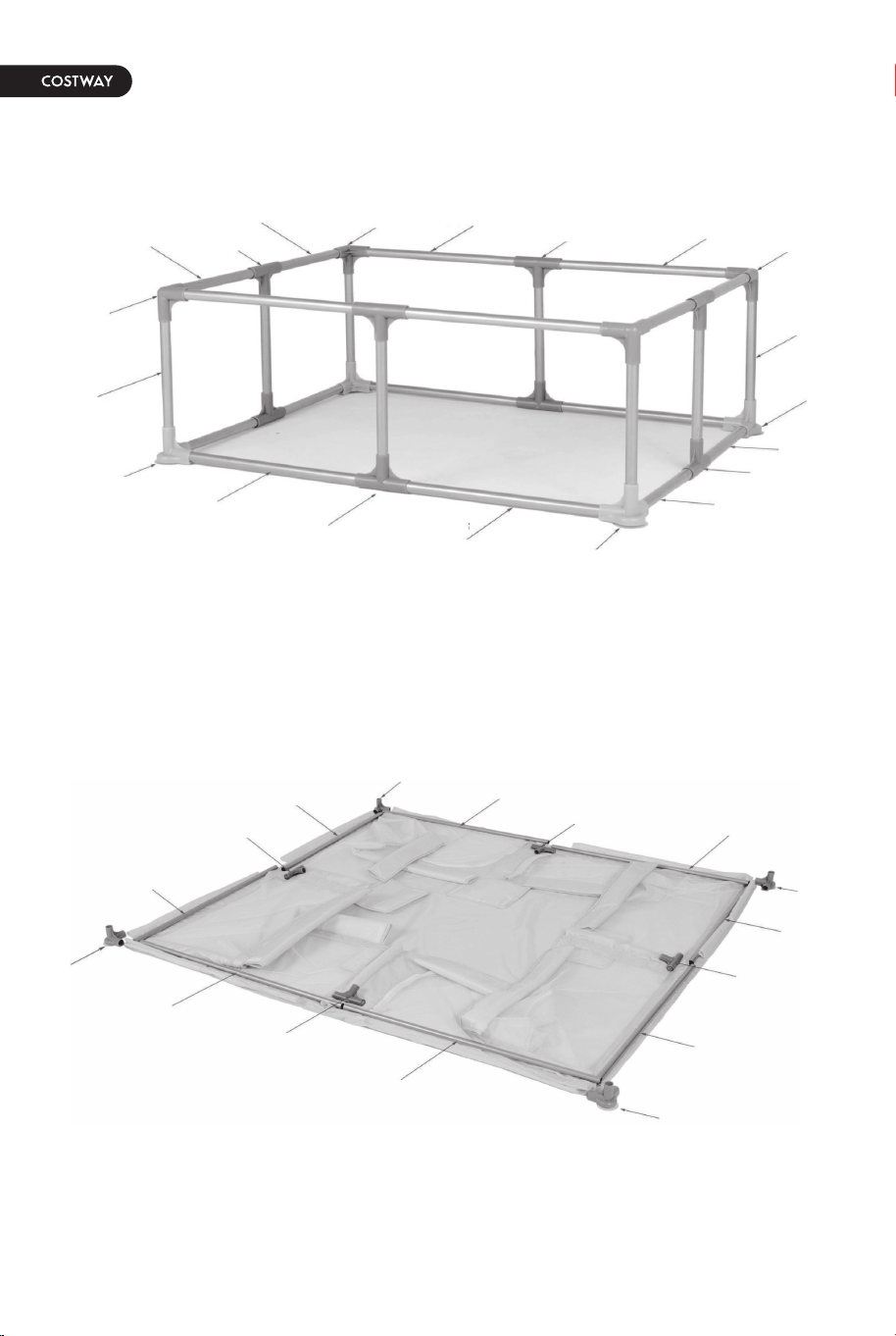
Diagramme de localisation des pièces
Étapes d’assemblage
Étape 1
717mm
Joint
en T
Joint en T
Joint en T
Joint en T
717mm
717mm
717mm
917mm
917mm
917mm
917mm
639mm
639mm
Joint à trois
voies
Joint à
ventouse
Joint à
ventouse
Joint à
ventouse
Joint à trois
voies
Joint à trois
voies
717mm
717mm
717mm
717mm
917mm
917mm
917mm
917mm
Joint à
ventouse
Joint à
ventouse
Joint à
ventouse
Joint à
ventouse
Joint en T
Joint en T
Joint en T
Joint en T
Étape 2
Étape 3
Joint en T
Joint en T
Joint en T
Joint en T
639mm
639mm
639mm
639mm
639mm
639mm
639mm
639mm
22
FR
23
Comme le montre la figure, placez 4 tuyaux inférieurs (917 mm) et 4 tuyaux inférieurs (717
mm) autour de la couverture en tissu, puis placez 4 joints en T au milieu, et 4 joints à
ventouse aux quatre coins de la couverture en tissu.
Note : Commencez par le milieu et ensuite par les deux côtés. Les tuyaux inférieurs sont
entièrement insérés dans le couvercle en toile, reliés aux joints en T comme le montre la
flèche rouge. Ensuite, on installe les joints à ventouses aux quatre coins.
Utilisez d’abord 8 tubes de colonne verticaux (639 mm) pour passer à travers la couverture
en tissu, et installez-les sur les joints en T et les joints à ventouses dans le sens indiqué par
la flèche rouge.
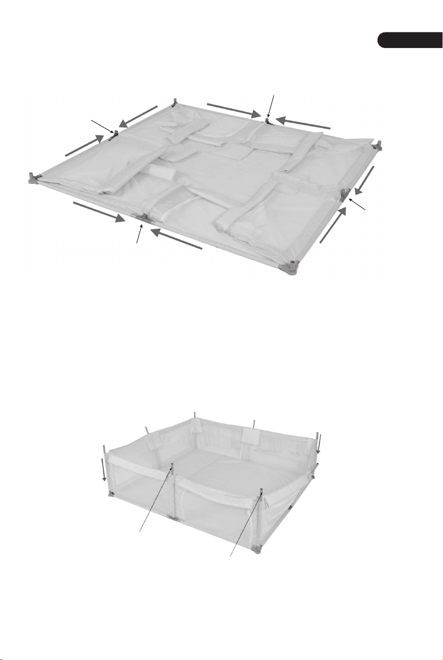
24
FR
25
Installez des joints en T et des joints à trois voies sur les tuyaux des colonnes verticales.
Comme le montre la figure, faites
pivoter le joint à trois voies de 50° dans
la direction de la flèche bleue pour
l’aligner avec le tuyau en acier, puis
tournez-le de 50° dans la direction de la
flèche rouge pour l’insérer dans le tuyau
en acier.
Comme le montre la figure, poussez le joint à trois voies vers l’avant dans le sens de la
flèche rouge, tirez le tuyau en acier vers l’arrière, aligné avec le joint à trois voies pour
insérer le tuyau en acier.
Les tuyaux supérieurs sont entièrement insérés dans la couverture en tissu comme le
montre la flèche rouge. Raccordez les joints à trois voies en plastique dans le sens des
aiguilles d’une montre.
Étape 4
Étape 5
Joint en T
Joint en T
Joint en T
Joint en T
Joint à trois
voies
Joint à trois
voies
Joint à trois
voies
Joint à trois
voies
Joint en T
Joint en T
Joint en T
Joint en T
Joint à trois
voies
Joint à trois
voies
Joint à trois
voies
Joint à trois
voies
Conseils pour
raccorder des
joints à trois voies
Conseils pour l’assemblage de la dernière étape
Pièce de couverture
26
Fermez la pièce de couverture et fermez la fermeture Éclair pour terminer l’assemblgae.
¡Por favor dénos una oportunidad para hacerlo bien y hacerlo mejor!
Primero póngase en contacto con nuestro amable departamento de
servicio al cliente para obtener ayuda. ¡Los reemplazos de piezas
faltantes o dañadas se enviarán lo antes posible!
¡Contáctenos!
NO devuelva este artículo.
ES : [email protected]
Primero póngase en contacto con nuestro amable departamento
de servicio al cliente para obtener ayuda.
Parque de Bebés
BB5560
MANUAL DEL USUARIO
ESTE MANUAL DE INSTRUCCIONES CONTIENE IMPORTANTES INFORMACIONES DE SEGURIDAD, POR FAVOR, LÉALO Y GUÁRDELO PARA FUTURAS CONSULTAS.
EN DE FR ES IT PL
Antes de Empezar
Advertencias Generales:
¡Peligro! Mantenga todas las piezas pequeñas y los materiales de embalaje de este
producto fuera del alcance de los bebés y los niños, ya que, de lo contrario, pueden
suponer un peligro de asfixia.
El producto debe instalarse y usarse bajo la supervisión de un adulto.
Lea cada paso cuidadosamente y siga el orden correcto.
Retire todo el embalaje, separe y cuente todas las piezas y los accesorios antes de
la instalación.
Asegúrese de que todas las piezas estén instaladas correctamente, una instalación
incorrecta puede provocar un peligro.
Asegure una superficie segura durante el montaje, y coloque el producto siempre
sobre una superficie plana, firme y estable.
Lea todas las instrucciones detenidamente y guárdelas para futuras referencias.
29
Scan QR code for
assembly instructions
Lista de piezas en la caja
Nombre
Tubo superior
Tubo inferior
Tubo superior
Tubo inferior
Lado Largo
Lado Corto
Tubo de
columna
vertical
917
717
639
8
8
8
8
4
4
Articulación
tipo T
Longitud (mm) Cantidad Figura
Articulación
de tres vías
Articulación
de ventosa
Como se muestra en la figura, coloque 4 tubos inferiores (917 mm) y 4 tubos inferiores
(717 mm) alrededor de la cubierta de tela, luego coloque 4 articulaciones de tipo T en el
medio y 4 articulaciones de ventosas en las cuatro esquinas de la cubierta de tela.
Diagrama de ubicación de piezas
Pasos de instalación
Paso 1
717mm
717mm
717mm
717mm
917mm
917mm
917mm
917mm
639mm
639mm
Articulación
de tres vías
Articulación
de tres vías
Articulación
de ventosa
Articulación
de ventosa
Articulación
de ventosa
Articulación
de tres vías
Articulación
tipo T
Articulación
tipo T
Articulación
tipo T
Articulación
tipo T
717mm
717mm
717mm
717mm
917mm
917mm
917mm
917mm
Articulación
de ventosa
Articulación
de ventosa
Articulación
de ventosa
Articulación
de ventosa
Articulación tipo T
Articulación tipo T
Articulación tipo T
Articulación tipo T
30
ES
31
32
ES
33
Nota: Comience desde el medio y luego desde ambos lados. Las tuberías inferiores están
completamente insertadas en la cubierta de tela, conectadas a las articulaciones de tipo T
como se muestra con la flecha roja. Luego instale las articulaciones de la ventosa en las
cuatro esquinas.
Utilice 8 tubos de columna verticales (639 mm) para pasar primero a través de la cubierta
de tela e instálelos en las articulaciones de tres vías y en las articulaciones de ventosa en la
dirección indicada por la flecha roja.
Paso 2
Paso 3
Articulación tipo T
Articulación
tipo T
Articulación tipo T
Articulación tipo T
639mm
639mm
639mm
639mm
639mm
639mm
639mm
639mm
Paso 4
Paso 5
Articulación
tipo T
Articulación
tipo T
Articulación
tipo T
Articulación
tipo T
Articulación
de tres vías
Articulación
de tres vías
Articulación
de tres vías
Articulación
de tres vías
Articulación
tipo T
Articulación
tipo T
Articulación
tipo T
Articulación
tipo T
Articulación
de tres vías
Articulación
de tres vías
Articulación
de tres vías
Articulación
de tres vías
Los tubos superiores están completamente insertados en la cubierta de tela como se
muestra con la flecha roja. Conecte las articulaciones plásticas de tres vías en sentido
horario.
Instale articulaciones de tipo T y articulaciones de tres vías en los tubos de columna
verticales.
Cierre la pieza de la cubierta y cierre la cremallera para completar el montaje.
34
ES
35
Como se muestra en la figura, gire la
articulación de tres vías 50 ° en la
dirección de la flecha azul para alinearla
con la tubería de acero, y luego gírela 50
° en la dirección de la flecha roja para
que encaje en la tubería de acero.
Como se muestra en la figura, empuje la articulación de tres vías hacia adelante en la
dirección de la flecha roja, tire de la tubería de acero hacia atrás, alineada con la
articulación de tres vías para insertar la tubería de acero.
Consejos para
conectar
articulaciones de
tres vías
Consejos de instalación del último paso
Pieza de Cubierta

Vi preghiamo di darci la possibilità di fare bene e fare di meglio!
Si prega di contattare prima il nostro servizio clienti per assistenza.
Le parti di ricambio per le parti mancanti o danneggiate verranno spedite al più presto!
Contattaci !
NON restituire questo articolo.
Si prega di contattare prima il nostro servizio clienti per assistenza.
Recinzione di Sicurezza per Bambini
MANUALE UTENTE
QUESTO MANUALE DI ISTRUZIONI CONTIENE IMPORTANTI INFORMAZIONI SULLA SICUREZZA. SI PREGA DI LEGGERE E CONSERVARE PER RIFERIMENTO FUTURO.
EN DE FR ES IT PL
BB5560
Scan QR code for
assembly instructions
Prima di iniziare
Avvertenza:
Pericolo! Tenere tutte le piccole parti e i materiali di imballaggio di questo prodotto
lontano da neonati e bambini, altrimenti potrebbero rappresentare un rischio di
soffocamento.
Il prodotto deve essere installato e utilizzato sotto la supervisione di un adulto.
Leggere attentamente ogni passo e seguire l'ordine corretto.
Rimuovere tutti gli imballaggi, separare e contare tutte le parti e tutti gli accessori.
Si prega di assicurarsi che tutte le parti siano installate correttamente,
un'installazione errata può portare a un pericolo.
Si consiglia, ove possibile, di montare tutti gli articoli vicino alla zona in cui verranno
posti in uso, per evitare di spostare inutilmente il prodotto una volta assemblato.
Garantire una superficie sicura durante il montaggio e posizionare il prodotto sempre
su una superficie piana, stabile.
Si prega di leggere attentamente tutte le istruzioni e conservarle per riferimento futuro.
38
IT
39
Elenco delle Parti nella Confezione
Nome
Tubo superiore
Tubo inferiore
Tubo superiore
Tubo inferiore
Lato lungo
Lato corto
Colonna
montante
verticale
917
717
639
8
8
8
8
4
4
Giunto a T
Lunghezza (mm) Quantità Figura
Giunto a tre
vie
Giunto a
ventosa
40
IT
41
Come mostrato nella figura, posizionare 4 tubi inferiori (917 mm) e 4 tubi inferiori (717
mm) intorno alla copertura in tessuto, quindi posizionare 4 giunti a T al centro e 4 giunti a
ventosa ai quattro angoli della copertura del tessuto.
Diagramma della Posizione delle Parti
Passi di Installazione
Passo 1
717mm
717mm
717mm
717mm
917mm
917mm
917mm
917mm
639mm
639mm
Giunto a tre
vie
Giunto a tre
vie
Giunto a
ventosa
Giunto a
ventosa
Giunto a
ventosa
Giunto a tre
vie
Giunto a T
Giunto a T
Giunto a T
Giunto a T
717mm
717mm
717mm
717mm
917mm
917mm
917mm
917mm
Giunto a
ventosa
Giunto a
ventosa
Giunto a
ventosa
Giunto a
ventosa
Giunto a T
Giunto a T
Giunto a T
Giunto a T
Utilizzare 8 tubi a colonna verticale (639 mm) per passare prima attraverso la copertura in
tessuto e installarli sui giunti a tre vie e sui giunti a ventosa nella direzione indicata dalla
freccia rossa.
Nota: Inizia dal centro e poi da entrambi i lati.
I tubi inferiori sono completamente inseriti nella copertura in tessuto, collegati ai giunti a T
come mostrato dalla freccia rossa. Quindi installare i giunti delle ventose ai quattro angoli.
Passo 2
Passo 3
Giunto a T
Giunto a T
Giunto a T
Giunto a T
639mm
639mm
639mm
639mm
639mm
639mm
639mm
639mm
42
IT
43
I tubi superiori sono completamente inseriti nella copertura in tessuto, come mostrato dalla
freccia rossa. Collegare i giunti a tre vie in plastica in senso orario.
Installare giunti a T e giunti a tre vie sui tubi della colonna verticale.
Passo 4
Passo 5
vie
Giunto a T
Giunto a T
Giunto a T
Giunto a T
Giunto a tre
vie
Giunto a tre
vie
Giunto a tre
Giunto a tre
vie
Giunto a T
Giunto a T
Giunto a T
Giunto a T
Giunto a tre
vie
Giunto a tre
vie
Giunto a tre
vie
Giunto a tre
vie
Come mostrato nella figura, ruotare il
giunto a tre vie di 50° nella direzione
della freccia blu per allinearlo al tubo
d'acciaio, quindi ruotarlo di 50° nella
direzione della freccia rossa per adattarlo
al tubo d'acciaio.
Come mostrato nella figura, spingere in avanti il giunto a tre vie nella direzione della freccia
rossa, tirare indietro il tubo d'acciaio, allineato con il giunto a tre vie per inserire il tubo
d'acciaio.
Suggerimenti per il
collegamento di
giunti a tre vie
Suggerimenti per l'installazione dell'ultimo
passo
Copertura
44
Chiudere il pezzo di copertura e la cerniera lampo per completare il montaggio.
Nie zwracaj tego produktu.
pomoc.

44
Chiudere il pezzo di copertura e la cerniera lampo per completare il montaggio.
Nie zwracaj tego produktu.
pomoc.
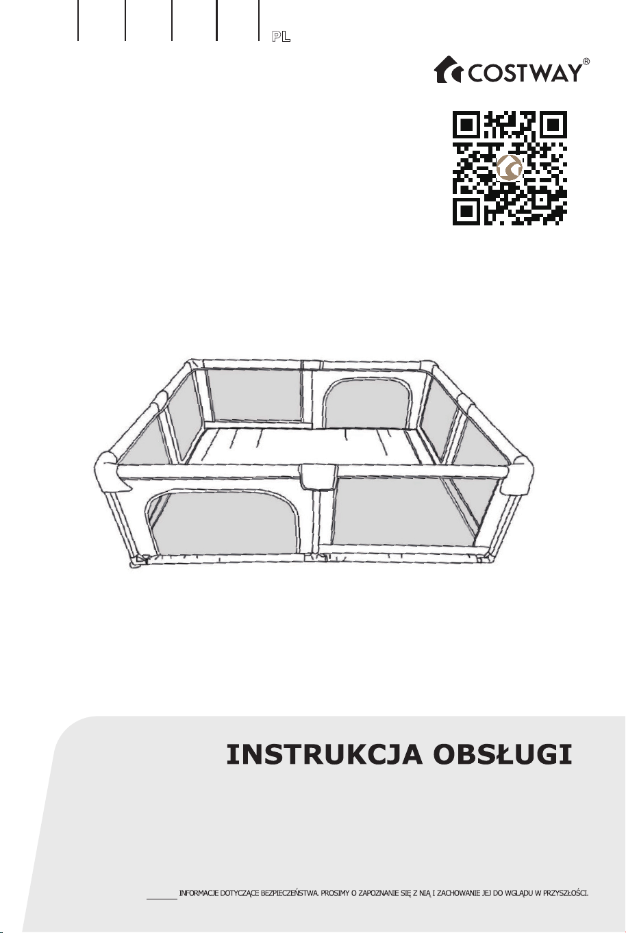
Ogrodzenie dla dzieci
NINIEJSZA INSTRUKCJA ZAWIERA ISTOTNE
EN DE FR ES IT PL
BB5560
Zanim Zaczniesz
47
Scan QR code for
assembly instructions
Ogrodzenie dla dzieci
NINIEJSZA INSTRUKCJA ZAWIERA ISTOTNE
EN DE FR ES IT PL
BB5560
Zanim Zaczniesz
47
Scan QR code for
assembly instructions
Jak pokazano na rysunku, umieść 4 dolne rurki (917 mm) i 4 dolne rurki (717 mm) wokół
pokrowca z tkaniny, a następnie umieść 4 złącza typu T na środku i 4 złącza z przyssawką w
rogach.
Schemat złożonych elementów
Kroki montażu
Krok 1
717mm
717mm
717mm
717mm
917mm
917mm
917mm
917mm
639mm
639mm
Złączka
narożna
Złączka
narożna
Złączka z
przyssawką
Złączka z
przyssawką
Złączka z
przyssawką
Złączka
narożna
Złącze
typu T
Złącze
typu T
Złącze typu T
Złącze typu T
717mm
717mm
717mm
717mm
917mm
917mm
917mm
917mm
Złączka z
przyssawką
Złączka z
przyssawką
Złączka z
przyssawką
Złączka z
przyssawką
Złącze typu T
Złącze typu T
Złącze typu T
Złącze typu T
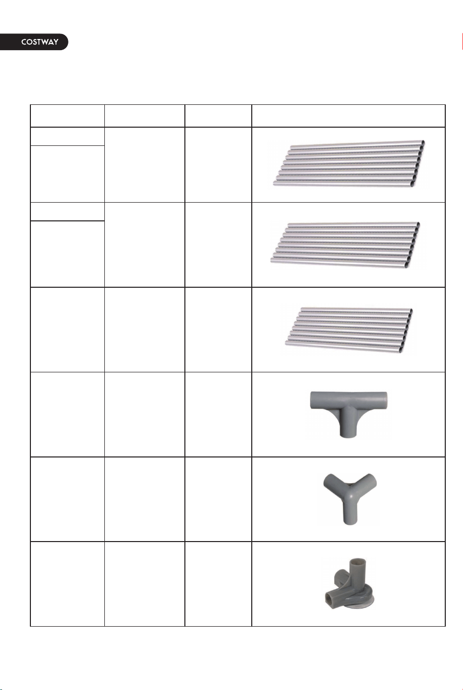
Lista części w pudełku
Nazwa
Górna rura
Dolna rura
Górna rura
Dolna rura
Długi bok
Krótka strona
Pionowa
rura
kolumny
917
717
639
8
8
8
8
4
4
Złącze
typu T
Długość (mm) Ilość Wygląd
Złączka
narożna
Złączka z
przyssawką
48
PL
49
Jak pokazano na rysunku, umieść 4 dolne rurki (917 mm) i 4 dolne rurki (717 mm) wokół
pokrowca z tkaniny, a następnie umieść 4 złącza typu T na środku i 4 złącza z przyssawką w
rogach.
Schemat złożonych elementów
Kroki montażu
Krok 1
717mm
717mm
717mm
717mm
917mm
917mm
917mm
917mm
639mm
639mm
Złączka
narożna
Złączka
narożna
Złączka z
przyssawką
Złączka z
przyssawką
Złączka z
przyssawką
Złączka
narożna
Złącze
typu T
Złącze
typu T
Złącze typu T
Złącze typu T
717mm
717mm
717mm
717mm
917mm
917mm
917mm
917mm
Złączka z
przyssawką
Złączka z
przyssawką
Złączka z
przyssawką
Złączka z
przyssawką
Złącze typu T
Złącze typu T
Złącze typu T
Złącze typu T
Lista części w pudełku
Nazwa
Górna rura
Dolna rura
Górna rura
Dolna rura
Długi bok
Krótka strona
Pionowa
rura
kolumny
917
717
639
8
8
8
8
4
4
Złącze
typu T
Długość (mm) Ilość Wygląd
Złączka
narożna
Złączka z
przyssawką
48
PL
49
Uwaga: zacznij od środka, a następnie z obu stron.
Dolne rury są całkowicie w tkaninie, połączone ze złączami typu T tak, jak pokazują
czerwone strzałki. Następnie zamocuj złącza z przyssawkami we wszystkich czterech
rogach.
Użyj 8 pionowych rurek kolumnowych (639 mm) i zamocuj je na złączach Ti narożnikach z
przyssawkami, mocując je w kierunku wskazanym przez czerwoną strzałkę.
Krok 2 Krok 4
Krok 5
Krok 3
Złącze typu T
Złącze typu T
Złącze typu T
Złącze typu T
639mm
639mm
639mm
639mm
639mm
639mm
639mm
639mm
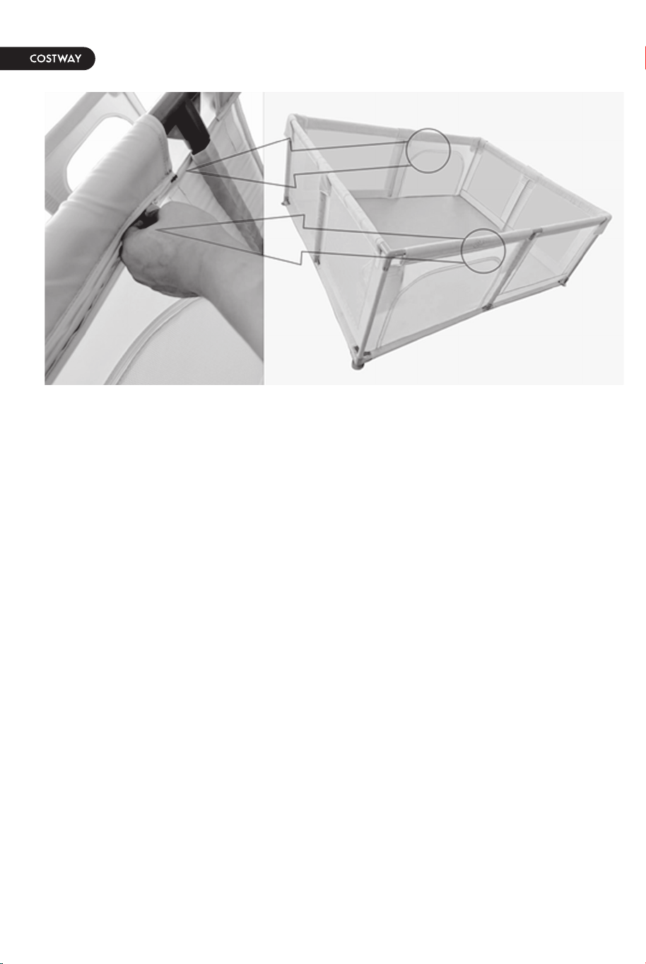
Górne rurki powinny znajdować się w tkaninie, tak jak pokazuje czerwona strzałka. Połącz
złącza rurkami zgodnie z ruchem wskazówek zegara.
Zamocuj złącza na górze pionowych rurek, analogicznie do tego jak zamocowane zostały na
dole.
Złącze typu T
Złącze typu T
Złącze typu T
Złącze typu T
Złączka
narożna
Złączka
narożna
Złączka
narożna
Złączka
narożna
Złącze typu T
Złącze typu T
Złącze typu T
Złącze typu T
Złączka
narożna
Złączka
narożna
Złączka
narożna
Złączka
narożna
50
PL
51
Uwaga: zacznij od środka, a następnie z obu stron.
Dolne rury są całkowicie w tkaninie, połączone ze złączami typu T tak, jak pokazują
czerwone strzałki. Następnie zamocuj złącza z przyssawkami we wszystkich czterech
rogach.
Użyj 8 pionowych rurek kolumnowych (639 mm) i zamocuj je na złączach Ti narożnikach z
przyssawkami, mocując je w kierunku wskazanym przez czerwoną strzałkę.
Krok 2 Krok 4
Krok 5
Krok 3
Złącze typu T
Złącze typu T
Złącze typu T
Złącze typu T
639mm
639mm
639mm
639mm
639mm
639mm
639mm
639mm
Górne rurki powinny znajdować się w tkaninie, tak jak pokazuje czerwona strzałka. Połącz
złącza rurkami zgodnie z ruchem wskazówek zegara.
Zamocuj złącza na górze pionowych rurek, analogicznie do tego jak zamocowane zostały na
dole.
Złącze typu T
Złącze typu T
Złącze typu T
Złącze typu T
Złączka
narożna
Złączka
narożna
Złączka
narożna
Złączka
narożna
Złącze typu T
Złącze typu T
Złącze typu T
Złącze typu T
Złączka
narożna
Złączka
narożna
Złączka
narożna
Złączka
narożna
50
PL
51
Jak pokazano na rysunku, obróć złączki o
50° w kierunku niebieskiej strzałki, aby
wmontować rurki, następnie obróć złączkę
o 50° w kierunku czerwonej strzałki, aby
dopasować do kolejnej rurki.
Załóż i zapnij materiał, montaż zakończony.
Wskazówki dotyczące
łączenia złączek.
Wskazówki dotyczące instalacji w ostatnim
kroku
Zakryj materiał
52
PL
53
Jak pokazano na rysunku, popchnij złącze do przodu w kierunku czerwonejz strzałki i
jednocześnie pociągnij rurkę do tyłu, wyrównując ją ze złączem i wprowadzić rurkę.

Please give us a chance to make it right and do better !
Contact our friendly customer service department for help first.
Replacements for missing or damaged parts will be shipped ASAP !
Contact Us !
Do NOT return this item.
US:cs.us@costway.com
UK:cs.uk@costway.com
Baby Playpen
BB5560
USER’S MANUAL
THIS INSTRUCTION BOOKLET CONTAINS IMPORTANT SAFETY INFORMATION. PLEASE READ AND KEEP FOR FUTURE REFERENCE.
EN DE FR ES IT PL
Scan QR code for
assembly instructions