THIS INSTRUCTION BOOKLET CONTAINS IMPORTANT SAFETY INFORMATION. PLEASE READ AND KEEP FOR FUTURE REFERENCE.
EN
DE
FR
ES
IT
PL
With your inspiring rating, COSTWAY will be more consistent to offer you EASY
SHOPPING EXPERIENCE, GOOD PRODUCTS and EFFICIENT SERVICE!
Mit Ihrer inspirierenden Bewertung wird COSTWAY konsistenter sein, um Ihnen EIN
SCHÖNES EINKAUFSERLEBNIS, GUTE PRODUKTE und EFFIZIENTEN SERVICE zu
bieten!
Avec votre évaluation inspirante, COSTWAY continuera à fournir une EXPÉRIENCE
D’ACHAT PRATIQUE, des PRODUITS DE QUALITÉ et un SERVICE EFFICACE !
Con su calificación inspiradora, COSTWAY será más consistente para ofrecerle
EXPERIENCIA DE COMPRA FÁCIL, BUENOS PRODUCTOS y SERVICIO EFICIENTE.
Con la tua valutazione incoraggiante, COSTWAY sarà più coerente per offrirti
ESPERIENZA DI ACQUISTO FACILE, BUONI PRODOTTI e SERVIZIO EFFICIENTE!
Dzięki twojej opinii COSTWAY będzie mógł oferować jeszcze WYGODNIEJSZE
ZAKUPY, LEPSZE PRODUKTY i SPRAWNIEJSZĄ OBSŁUGĘ KLIENTA.
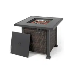
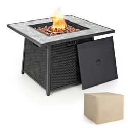
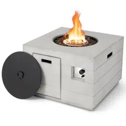
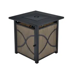
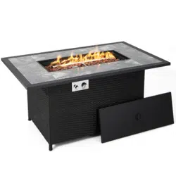
FIRE PIT
NP10464US
USER’S MANUAL
US office: Fontana UK office: Ipswich AU office: Truganina
DE office: Hamburg
FR office: Saint Vigor d'Ymonville
PL office: Gdańsk
02 03
ANS Z21.97 CSA 2.41-2017
Outdoor Decorative Gas Appliances
INSTALLER: Leave this manual with the appliance.
CONSUMER: Retain this manual for future reference
WARNING: For Outdoor Use Only.
DANGER
FIRE OR EXPLOSION HAZARD
WARNING
Do not store or use gasoline, or other flammable vapors and
liquids,in the vicinity of this or any other appliance.
An LP-cylinder not connected for use shall not be stored in the
vicinity of this or any other appliance.
Installation and service must be performed by a qualified
installer, service agency, or the gas supplier.
If the information in this manual is not followed exactly, a
fire or explosion may result in causing property damage,
personal injury, or loss of life.
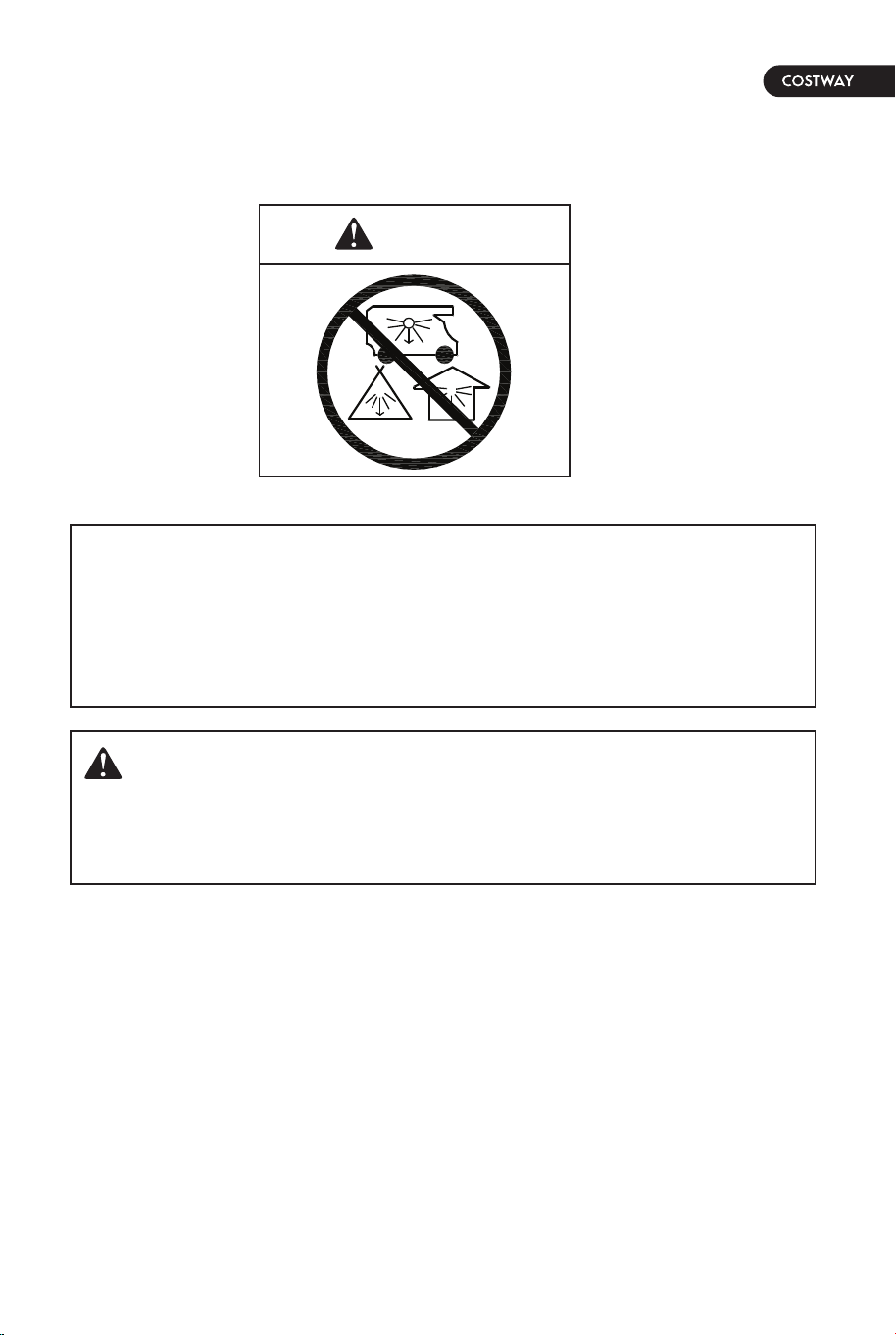
DANGER
CARBON MONOXIDE HAZARD
This appliance can produce carbon monoxide which has no odor.
Using it in an enclosed space can kill you.
Never use this appliance in an enclosed space such as a camper,
tent, car or home.
WARNING:
If you smell gas:
Shut off gas to the appliance.
Extinguish any open flame.
If odor continues, leave the area immediately.
After leaving the area, call your gas supplier or fire department.
Failure to follow these instructions could result in fire or explosion,
which could cause property damage, personal injury, or death.
02 03
ANS Z21.97 CSA 2.41-2017
Outdoor Decorative Gas Appliances
INSTALLER: Leave this manual with the appliance.
CONSUMER: Retain this manual for future reference
WARNING: For Outdoor Use Only.
DANGER
FIRE OR EXPLOSION HAZARD
WARNING
Do not store or use gasoline, or other flammable vapors and
liquids,in the vicinity of this or any other appliance.
An LP-cylinder not connected for use shall not be stored in the
vicinity of this or any other appliance.
Installation and service must be performed by a qualified
installer, service agency, or the gas supplier.
If the information in this manual is not followed exactly, a
fire or explosion may result in causing property damage,
personal injury, or loss of life.
DANGER
CARBON MONOXIDE HAZARD
This appliance can produce carbon monoxide which has no odor.
Using it in an enclosed space can kill you.
Never use this appliance in an enclosed space such as a camper,
tent, car or home.
WARNING:
If you smell gas:
Shut off gas to the appliance.
Extinguish any open flame.
If odor continues, leave the area immediately.
After leaving the area, call your gas supplier or fire department.
Failure to follow these instructions could result in fire or explosion,
which could cause property damage, personal injury, or death.

04 05
The installation must conform with local codes or, in the absence
of local codes, with the National Fuel Gas Code, ANSI Z223.1 ●
NFPA 54; National Fuel Gas Code; Natural Gas and Propane
Installation Code, CSA B149.1; or Propane Storage and Handling
Code, CSA B149.2, as applicable.
The appliance must be isolated from the gas supply piping
system by closing its individual manual shutoff valve during any
pressure testing of the gas supply piping system at test
pressures equal to or less than 1/2 psi (3.5 kPa).
The appliance area must be kept clear and free from combustible
materials, gasoline, and other flammable vapors and liquids.
Do not use this appliance if any part has been under water.
Immediately call a qualified service technician to inspect the
appliance and to replace any part of the control system and any
gas control that has been under water.
Children and adults should be alerted to the hazards of high
surface temperatures and should stay away to avoid burns or
clothing ignition.
Young children should be carefully supervised when they are in
the area of the appliance.
Clothing or other flammable materials should not be hung from
the appliance or placed on or near the appliance.
Any guard or other protective device removed for servicing the
appliance shall be replaced prior to operating the appliance.
Installation and repair should be done by a qualified service
person. The appliance should be inspected before use and at
least annually by a qualified service person. More frequent
cleaning may be required as necessary. It is imperative that the
control compartment, burners, and circulating air passageways
of the appliance are kept clean.
CAUTION: The propane gas pressure regulator provided with this
appliance must be used. This regulator is set for an outlet
pressure of 11 inches water column.
DO NOT burn solid fuels in this appliance.
This outdoor gas appliance is for Outdoor Use ONLY.
This outdoor gas appliance is not intended to be installed in or
on recreational vehicles and/or boats.
This outdoor appliance is not for use on wood decks or other
flammable surface.
Before each use of this gas appliance, open the door and/or the
propane Tank Drawer and inspect the hose. If there is evidence
of excessive abrasion or wear or if the hose is damaged, the
hose assembly must be replaced prior to the appliance being put
into operation. Use only the replacement hose assembly
specified in this manual.
Make sure to leak test.
Before each use of this gas appliance, inspect the burner. The
burner must be replaced prior to the appliance being put into
operation if it is evident that the burner is damaged. Use only
the replacement burner specified in this manual.
Make sure to properly locate the gas hose including locating the
hose out of pathways where people may trip over it or in areas
where the hose may be subject to accidental damage.
Keep the fuel supply hose away from any heated surface.
Never use this appliance closer than 10 feet from anything
flammable, including houses or overhead tree branches.
Never use gasoline, kerosene, or any other liquid fuel to start a
fire.
Always maintain a safe distance from the fire.
Always supervise children around the fire.
Never leave a fire unattended.
The appliance is hot during and after use, always allow ample
cooling time before touching or moving.
1.
2.
3.
4.
5.
6.
7.
8.
9.
10.
11.
12.
13.
14.
15.
16.
17.
18.
19.
20.
21.
22.
23.
24.
IMPORTANT SAFETY INFORMATION

1.
2.
3.
4.
5.
6.
7.
8.
9.
10.
11.
The propane supply cylinder to be used must be constructed
and marked in accordance with the U.S. Deparment of
Transportation (D.O.T.) Specifications for propane cylinders, or
the Standard for Cylinders, Spheres and Tubes for
Transportation of Dangerous Goods and Commission,
CAN/CSA-B339, as applicable.
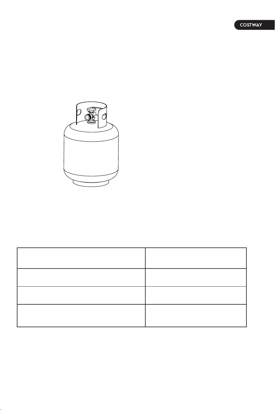
The propane supply cylinder to be used must have a listed
overfilling prevention device (See Figure 1).
The propane supply cylinder to be used must have a cylinder
connection device compatible with the connection for the
appliance.
A self-contained propane cylinder for use with this appliance
must have a capacity of 20 lbs cylinder (Height approximately
18 in., Tank Body approximately 12 in. diameter, Base
approximately 8 in. diameter).
The cylinder supply system must be arranged for vapor
withdrawl.
The cylinder used must include a collar to protect the cylinder
valve.
This appliance shall be used only outdoors in a well-ventilated
space and shall not be used in a building, garage or any other
enclosed space.
When this appliance is not in use, the gas must be turned off at
the supply cylinder.
Storage of this appliance indoors is permissible only if the
cylinder is disconnected and removed from the appliance.
Cylinders must be stored outdoors in a well-ventilated area out
of the reach of children. Disconnected cylinders must have
threaded valve plugs tightly installed and must not be stored in
a building, garage or any other enclosed areas.
This appliance is certified by CSA (Canadian Standards
Association) to ANS Z21.97 ● CSA 2.41-2017, Outdoor
Decorative Gas Appliances.
IMPORTANT SAFETY INFORMATION ABOUT
PROPANE GAS
Standard 20 lb.tank
Figure 1
SPECIFICATIONS
Rated Heat Input (Liquid Propane &
Natural Gas)
Propane Regulator Pressure
Natural Gas Inlet Pressure
Clearance to combustible surfaces
50,000 BTU/hr
11 inches water column
7 inches water column
Sides: 24in. (610mm),
Top: 72in. (1829mm)
06 07
1.
2.
3.
4.
5.
6.
7.
8.
9.
10.
11.
The propane supply cylinder to be used must be constructed
and marked in accordance with the U.S. Deparment of
Transportation (D.O.T.) Specifications for propane cylinders, or
the Standard for Cylinders, Spheres and Tubes for
Transportation of Dangerous Goods and Commission,
CAN/CSA-B339, as applicable.
The propane supply cylinder to be used must have a listed
overfilling prevention device (See Figure 1).
The propane supply cylinder to be used must have a cylinder
connection device compatible with the connection for the
appliance.
A self-contained propane cylinder for use with this appliance
must have a capacity of 20 lbs cylinder (Height approximately
18 in., Tank Body approximately 12 in. diameter, Base
approximately 8 in. diameter).
The cylinder supply system must be arranged for vapor
withdrawl.
The cylinder used must include a collar to protect the cylinder
valve.
This appliance shall be used only outdoors in a well-ventilated
space and shall not be used in a building, garage or any other
enclosed space.
When this appliance is not in use, the gas must be turned off at
the supply cylinder.
Storage of this appliance indoors is permissible only if the
cylinder is disconnected and removed from the appliance.
Cylinders must be stored outdoors in a well-ventilated area out
of the reach of children. Disconnected cylinders must have
threaded valve plugs tightly installed and must not be stored in
a building, garage or any other enclosed areas.
This appliance is certified by CSA (Canadian Standards
Association) to ANS Z21.97 ● CSA 2.41-2017, Outdoor
Decorative Gas Appliances.
IMPORTANT SAFETY INFORMATION ABOUT
PROPANE GAS
Standard 20 lb.tank
Figure 1
SPECIFICATIONS
Rated Heat Input (Liquid Propane &
Natural Gas)
Propane Regulator Pressure
Natural Gas Inlet Pressure
Clearance to combustible surfaces
50,000 BTU/hr
11 inches water column
7 inches water column
Sides: 24in. (610mm),
Top: 72in. (1829mm)
06 07
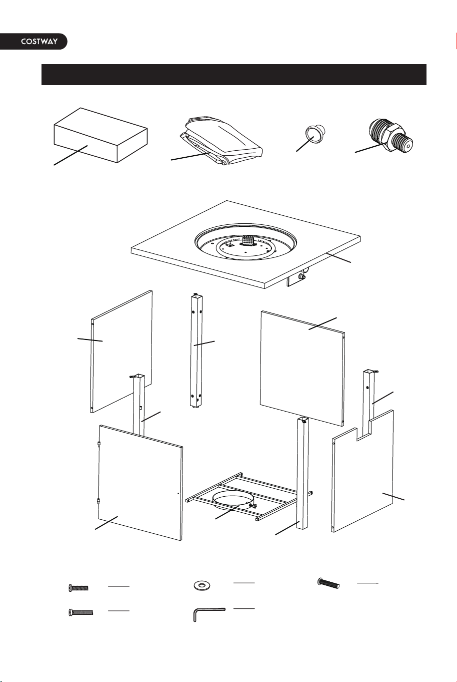
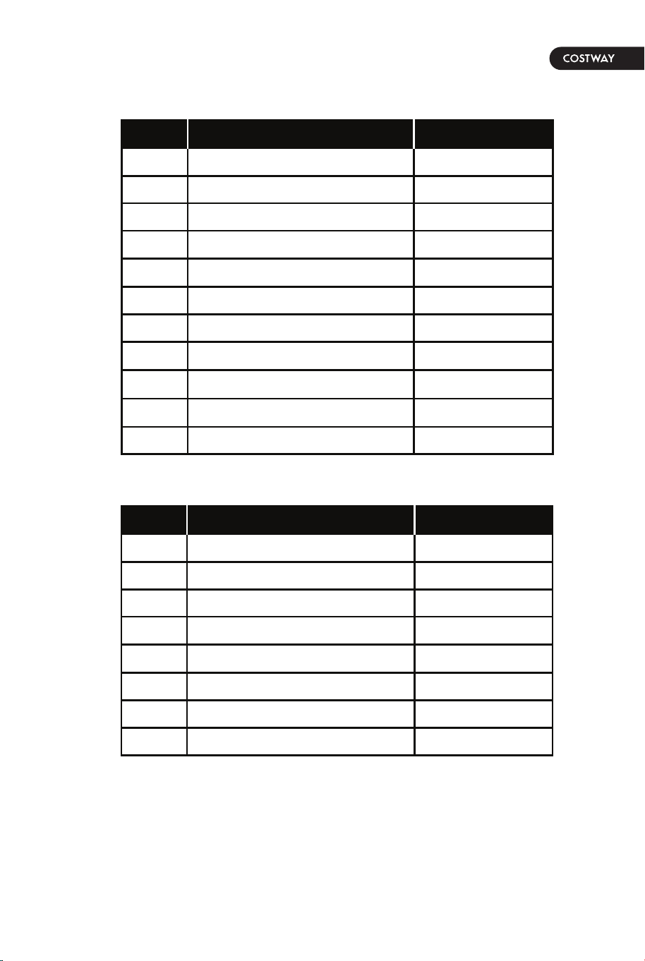
PACKAGE CONTENTS
08 09
A 1 pc
B 1 pc
C
1 pc
D 1 pc
E 1 pc
F 1 pc
G 1 pc
H 1 pc
I 1 pc
J 1 pc
K
Natural gas orifice
Front panel
Door panel
Back panel
Right panel
Front-right leg
Front-left leg
Back-left leg
Back-right leg
Gas cylinder support
Table top assembly
PART DESCRIPTION QUANTITY
PART DESCRIPTION QUANTITY
L
2 pack
N
1 pc
AA 16 pcsBolt (M6 x 15)
Bolt (M6 x 25) BB
CC
4 pcs
Washer (M6)
DD
20 pc
Hex screw driver 1 pc
DD 1 pcBolt (M4 x 10)
Lava rock
Weather cover
Q
1 pc
1 pc
Door handle
AA
BB
EE
CC
DD
N
L
K
Q
B
A
F
I
H
E
D
C
G
J
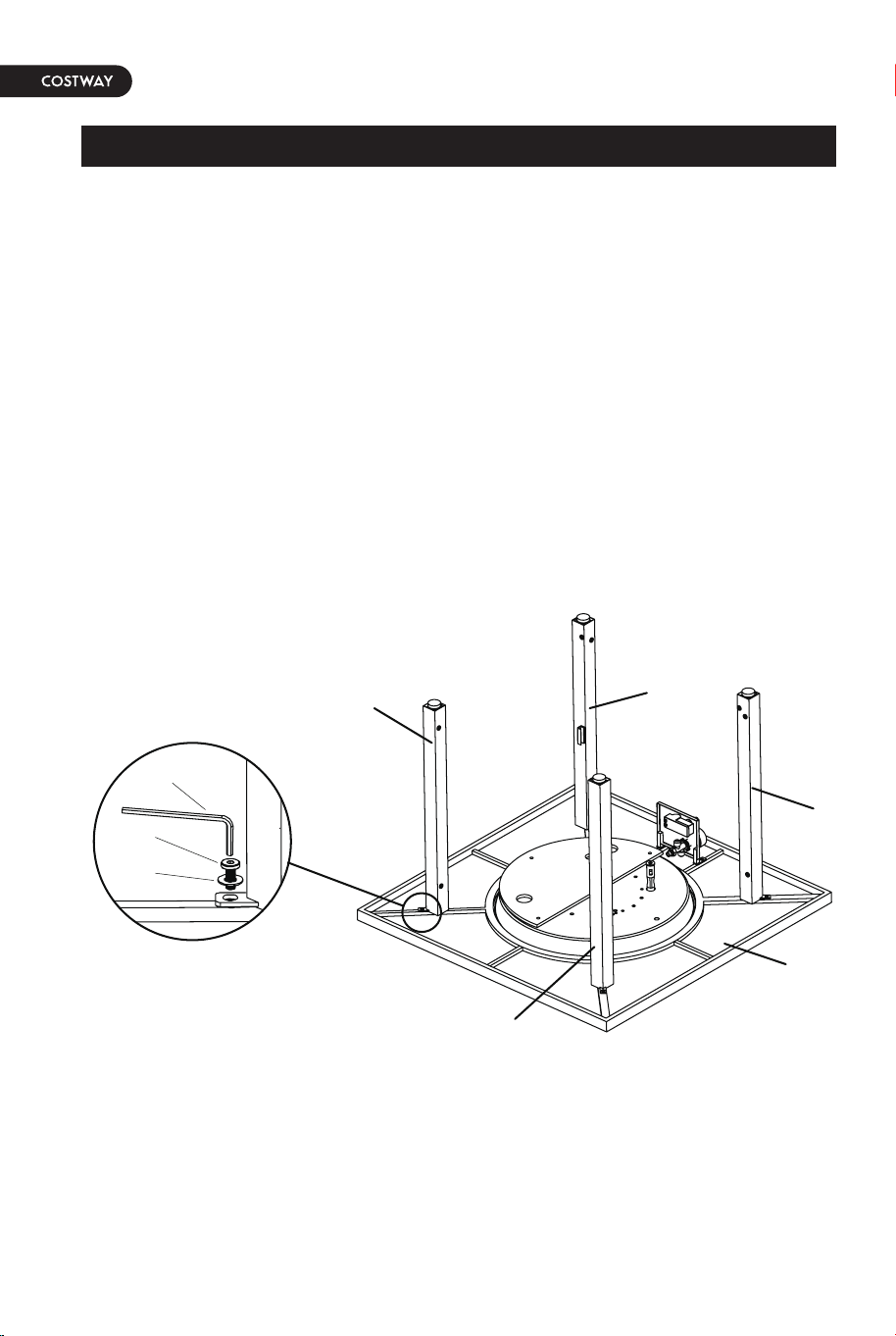
Figure 2
Figure 3
Figure 4
1. Carefully unpack all parts from the box, compare parts with
package content listed above, make sure all parts are present
before beginning assembly of product. If any part is missing or
damaged, do not attempt to assemble the product.
2. Attach back-left leg (H) and back-right leg (I) and front-left leg
(G) and front-right leg (F) to table top assembly (A) with bolts (AA)
and washer (CC) by using hex screw driver (DD), (see Figure 2).
NOTE: DO NOT tighten the screws completely.
Hardware Used:
AA Bolts (M6 x 15) x 4
CC Washer (M6) x 4
DD Hex screw driver x 1
3. Attach front panel (B) to front-left leg (G) and front-right leg (F)
with bolts (AA) and washer (CC) using hex screw driver (DD), (see
Figure 3).
NOTE: DO NOT tighten the screws completely.
Hardware Used:
AA Bolts (M6 x 15) x 4
CC Washer (M6) x 4
DD Hex screw driver x 1
4. Attach right panel (E) to front-right leg (F) and back-right leg (I)
with bolts (AA) and washer (CC) using hex screw driver (DD),
(see Figure 4).
NOTE: DO NOT tighten the screws completely.
Hardware Used:
AA Bolts (M6 x 15) x 4
CC Washer (M6) x 4
DD Hex screw driver x 1
10 11
ASSEMBLY INSTRUCTIONS
F
A
I
H
G
DD
AA
CC
B
F
G
DD
AA
CC
F
I
E
DD
AA
CC
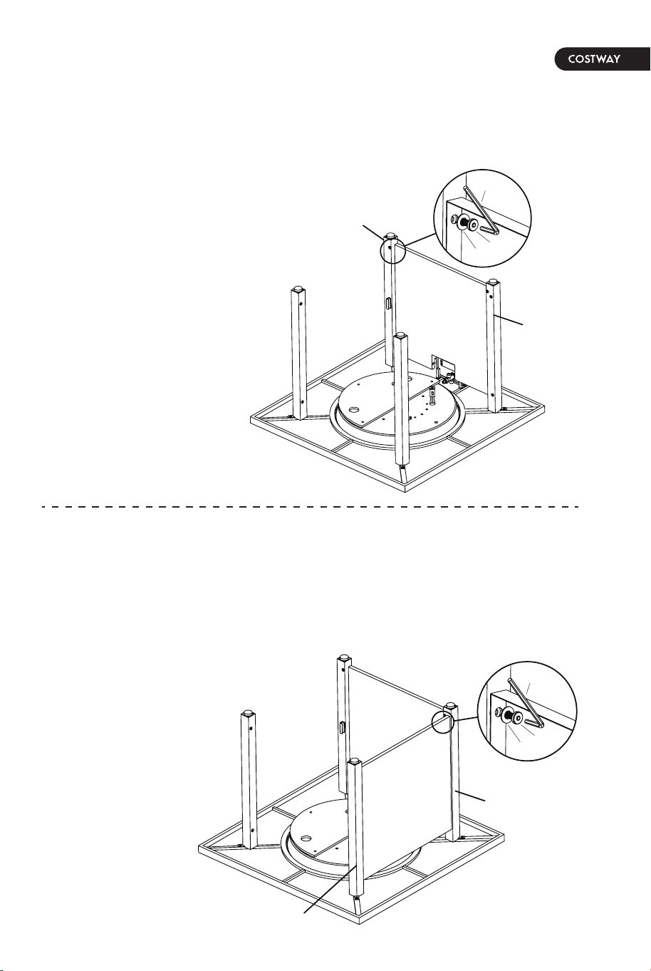
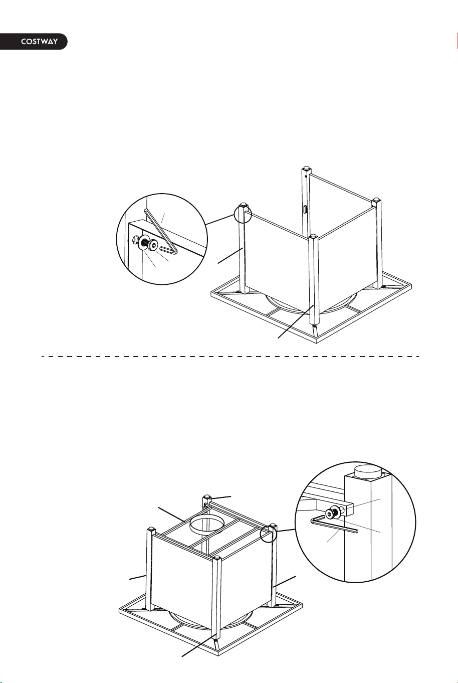
Figure 8
8. Attach the door handle (N) to the door panel (C) with the bolt
(EE) using a Phillips screwdriver (NOT included), (see Figure 8).
Hardware Used:
EE Bolt (M4 x 10) x 1
Figure 5
Figure 6
Figure 7
5. Attach back panel (D) to back-left leg (H) and back-right leg (I)
with bolts (AA) and washer (CC) using hex screw driver (DD),
(see Figure 5).
NOTE: DO NOT tighten the screws completely.
Hardware Used:
AA Bolts (M6 x 15) x 4
CC Washer (M6) x 4
DD Hex screw driver x 1
6. Attach gas cylinder support (J) to back-left leg (H) and back-right
leg (I) and front-left leg (G) and front-right leg (F) with bolts (BB)
and washer (CC) using hex screw driver (DD), (see Figure 6).
NOTE: Tighten all screws completely.
Hardware Used:
BB Bolts (M6 x 25) x 4
CC Washer (M6) x 4
DD Hex screw driver x 1
7. With the help of another person, carefully turn the fire pit to the
upright position. Attach the door panel (C) to the back-left leg (H)
by aligning the hinge on the door panel with those on the back-left
leg (H) and inserting the pins in the hinges, (see Figure 7).
12 13
I
H
D
DD
AA
CC
I
F
G
H
J
BB
DD
CC
H
C
C
N
EE
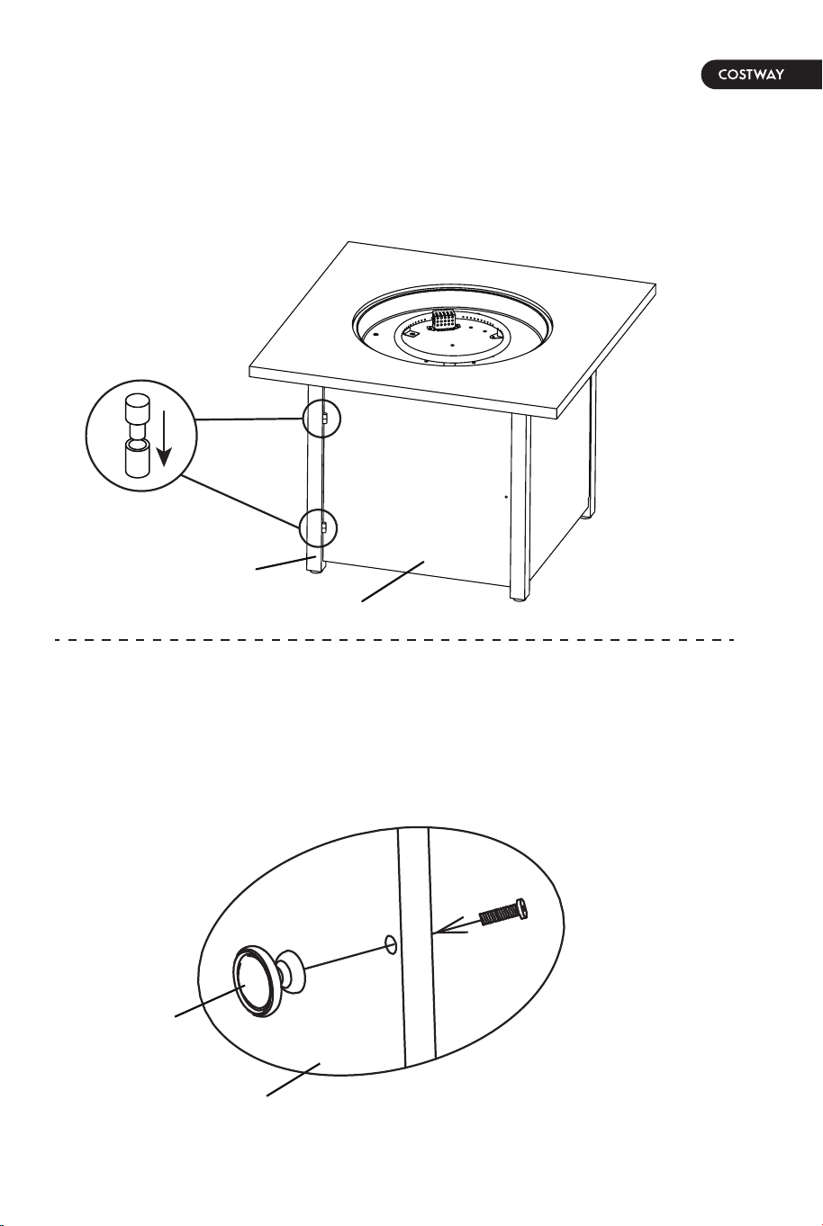
CAUTION: Please be advised that this fire pit is
equipped with natural lava rock that may crackle or pop
the first time it is used. The lava rock has been
pre-heat treated to release any natural inherent
moisture. However, in rare cases on first time use, the
lava rock may pop or burst causing small pieces of hot
rock to potentially be a projectile. These hot pieces
could cause injury or property damage. As a
precaution, please follow these instructions the first
time the fire pit is used:
(1). On first use, do not stand over or near the fire pit
once lit.
(2). Light the fire pit and let it run on high for 20
minutes.
(3). Once lit, do not go within 12 feet of the fire pit for
at least the first 20 minutes on the first use to ensure
any residual moisture trapped in the rocks gets
released.
(4). After the first heating cycle, there is little further
concern. It is rare that any crackling will happen on the
first use, this is simply a precaution.
(5). Keep lava rock covered and dry when not in use to
prevent additional moisture from getting in the rocks.
(6). If lava rocks are exposed to moisture after first
use, run the burner on low to gradually warm and dry
the rocks before repeating steps 1 through 3.
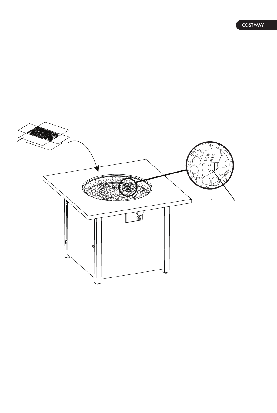
9. Open the box of lava rocks, put the lava rocks (K) into the fire
bowl of the fire table, (see Figure 9). A gas fire pit requires 13.2 lbs
lava rocks.
WARNING: Keep children away during assembly, as this item
contains lava rock, which are small pieces and can be swallowed by
children.
NOTE: Leave the pilot box uncovered by the lava rock.
Figure 9
pilot box
K
14 15
CAUTION: Please be advised that this fire pit is
equipped with natural lava rock that may crackle or pop
the first time it is used. The lava rock has been
pre-heat treated to release any natural inherent
moisture. However, in rare cases on first time use, the
lava rock may pop or burst causing small pieces of hot
rock to potentially be a projectile. These hot pieces
could cause injury or property damage. As a
precaution, please follow these instructions the first
time the fire pit is used:
(1). On first use, do not stand over or near the fire pit
once lit.
(2). Light the fire pit and let it run on high for 20
minutes.
(3). Once lit, do not go within 12 feet of the fire pit for
at least the first 20 minutes on the first use to ensure
any residual moisture trapped in the rocks gets
released.
(4). After the first heating cycle, there is little further
concern. It is rare that any crackling will happen on the
first use, this is simply a precaution.
(5). Keep lava rock covered and dry when not in use to
prevent additional moisture from getting in the rocks.
(6). If lava rocks are exposed to moisture after first
use, run the burner on low to gradually warm and dry
the rocks before repeating steps 1 through 3.
9. Open the box of lava rocks, put the lava rocks (K) into the fire
bowl of the fire table, (see Figure 9). A gas fire pit requires 13.2 lbs
lava rocks.
WARNING: Keep children away during assembly, as this item
contains lava rock, which are small pieces and can be swallowed by
children.
NOTE: Leave the pilot box uncovered by the lava rock.
Figure 9
pilot box
K
14 15
16 17
Figure 10
Figure 11
black handle
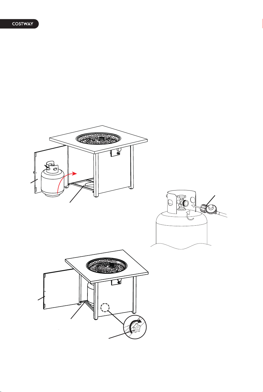
10. Open the door panel (C). Place the gas cylinder into the gas
cylinder support (J) and connect the regulator by turning the black
handle clockwise to tighten. To remove the regulator, turn the black
handle counter-clockwise.
Secure the gas cylinder by tightening clockwise the retention point
found on gas cylinder support (J), (see Figure 10), so that the gas
cylinder cannot move from side to side or fall down. The knob on
the control panel is turned all the way to the “OFF” position when
the fire pit in NOT in use.
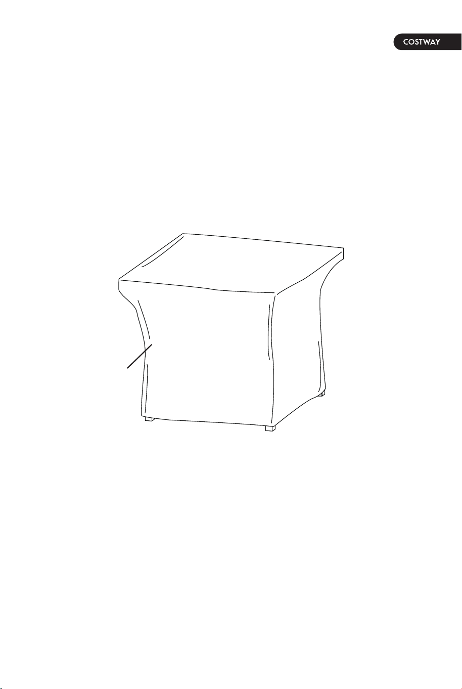
11. Cover the fire pit with the outdoor weather cover (L) when
not in use to protect it from the elements or when fire pit is cool
COMPLETELY after the use, (see Figure 11).
L
C
J
retention point
J
C
16 17
Figure 10
Figure 11
black handle
10. Open the door panel (C). Place the gas cylinder into the gas
cylinder support (J) and connect the regulator by turning the black
handle clockwise to tighten. To remove the regulator, turn the black
handle counter-clockwise.
Secure the gas cylinder by tightening clockwise the retention point
found on gas cylinder support (J), (see Figure 10), so that the gas
cylinder cannot move from side to side or fall down. The knob on
the control panel is turned all the way to the “OFF” position when
the fire pit in NOT in use.
11. Cover the fire pit with the outdoor weather cover (L) when
not in use to protect it from the elements or when fire pit is cool
COMPLETELY after the use, (see Figure 11).
L
C
J
retention point
J
C
18 19
Natural gas conversion must be performed only by natural gas
provider or a service company.
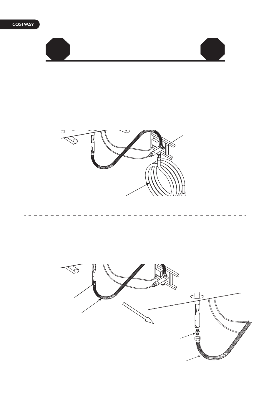
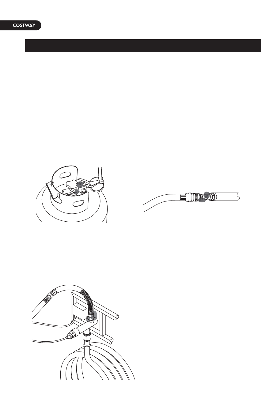
1. Disconnect the propane hose from the gas valve (see Figure 12).
Caution: The propane tank shall be shut off prior to disconnecting
the propane hose, before proceeding with the conversion.
2. Unscrew and disconnect the propane orifice from the bellows (see
Figure 13). Propane orifice (2.21 mm diameter size) is painted with
red mark.
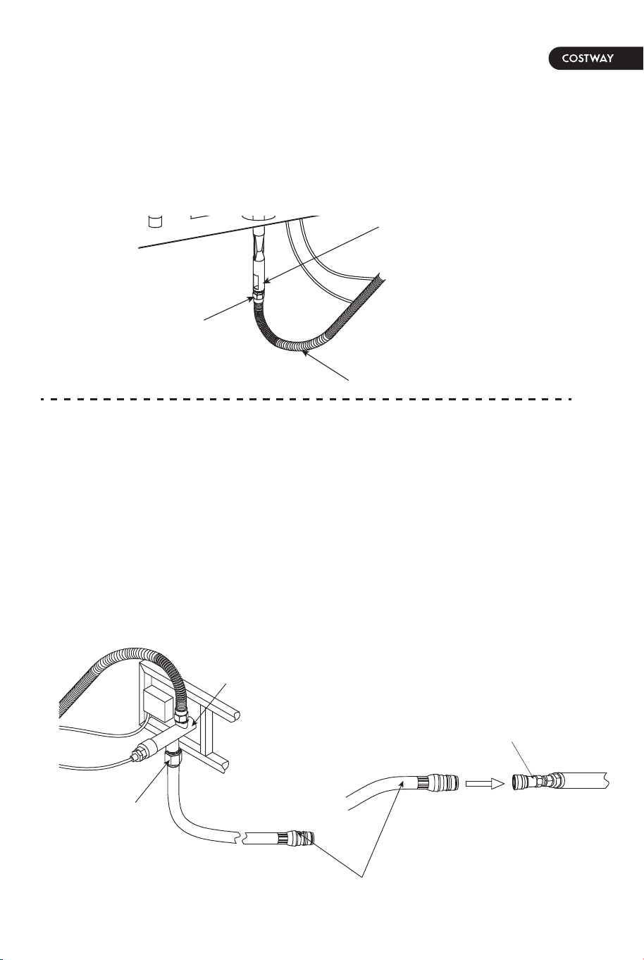
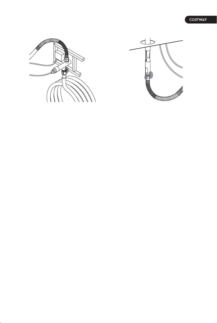
4. Connect the natural gas hose to the gas valve by screwing
clockwise tightly (see Figure 15). Plug the natural gas fixture into
the natural gas supply system (see Figure 16). The conversion kit
should be CSA certified. Below are several suggested CSA certified
conversion kits for your reference.
(1). Part# DH22 / QH1, manufacturer: KSUN
or (2). Part# WH02 / KJ50A2, manufacturer: Laite
or (3). Part# KJ-3/8G-3/8 / KJ-3/8G, manufacturer: Wanan
The natural gas orifice is included in the package. Please follow the
instructions for gas conversion.
3. Replace the propane orifice with the natural gas orifice and screw
the natural gas orifice to the bellows tightly.
Then connect and tighten the natural gas orifice to the inlet tube
(see Figure 14). The Natural gas orifice (4.18 mm diameter size ) is
painted with a black mark.
Figure 12
Figure 13
STOP STOP
NATURAL GAS CONVERSION
gas valve
propane hose
propane orifice
bellows
propane orifice
bellows
Figure 15
Figure 16
gas valve
natural gas hose
natural gas fixture
natural gas supply system
Figure 14
inlet tube
bellows
natural gas orifice
18 19
Natural gas conversion must be performed only by natural gas
provider or a service company.
1. Disconnect the propane hose from the gas valve (see Figure 12).
Caution: The propane tank shall be shut off prior to disconnecting
the propane hose, before proceeding with the conversion.
2. Unscrew and disconnect the propane orifice from the bellows (see
Figure 13). Propane orifice (2.21 mm diameter size) is painted with
red mark.
4. Connect the natural gas hose to the gas valve by screwing
clockwise tightly (see Figure 15). Plug the natural gas fixture into
the natural gas supply system (see Figure 16). The conversion kit
should be CSA certified. Below are several suggested CSA certified
conversion kits for your reference.
(1). Part# DH22 / QH1, manufacturer: KSUN
or (2). Part# WH02 / KJ50A2, manufacturer: Laite
or (3). Part# KJ-3/8G-3/8 / KJ-3/8G, manufacturer: Wanan
The natural gas orifice is included in the package. Please follow the
instructions for gas conversion.
3. Replace the propane orifice with the natural gas orifice and screw
the natural gas orifice to the bellows tightly.
Then connect and tighten the natural gas orifice to the inlet tube
(see Figure 14). The Natural gas orifice (4.18 mm diameter size ) is
painted with a black mark.
Figure 12
Figure 13
STOP STOP
NATURAL GAS CONVERSION
gas valve
propane hose
propane orifice
bellows
propane orifice
bellows
Figure 15
Figure 16
gas valve
natural gas hose
natural gas fixture
natural gas supply system
Figure 14
inlet tube
bellows
natural gas orifice
20 21
BATTERY
Figure 17
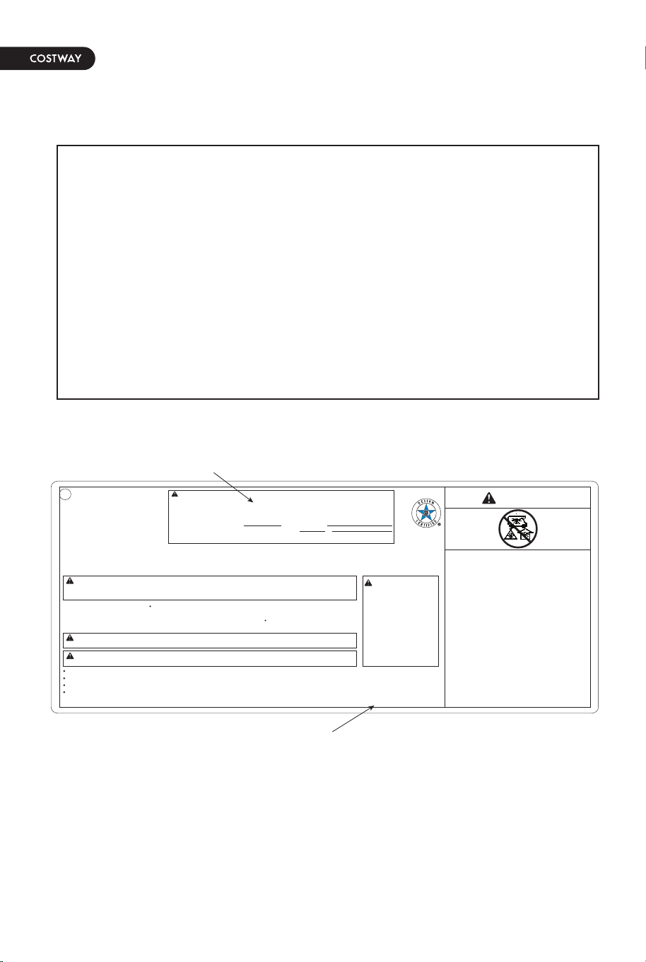
5. Stick and cover the conversion label onto the propane rating
plate (see Figure 17).
WARNING: This conversion kit shall be installed by a qualified
service agency in accordance with the manufacturer’s
instructions and all applicable codes and requirements of the
Authority Having Jurisdiction.
If the information in these instructions is not followed exactly, a
fire, explosion or production of carbon monoxide may result in
causing property damage, personal injury or loss of life. The
qualified service agency is responsible for the proper installation
of this kit. The installation is not proper and complete until the
operation of the converted appliance is checked as specified in
the manufacturer’s instructions supplied with the kit.
GOPLUS CORP
11250 poplar Ave,
Fontana.Ca92337
WARNING: If the information in this manual is not followed exactly, a fire or explosion may result causing
property damage, personal injury, or loss of life.
Serial No:
Model No:
DANGER
CARBON MONOXIDE
HAZARD
This appliance can
produce carbon
monoxide which has no
odor. Using it in an
enclosed space can kill
you. Never use this
appliance in an enclosed
space such as a camper,
tent, car or home.
WARNING:
WARNING: Placing the cylinder too close to the appliance might cause the fire hazard or property loss or
even life hazard.
Type of gas: propane
Normal hourly input: 50,000BTU/hr (14.65 kW)
Manifold pressure: 11 inch w.c. (2.74 kPa)
Maximum inlet supply pressure: 13 inch w.c. (3.24 kPa)
Minimum inlet supply pressure: 8 inch w.c. (1.99 kPa)
CAUTION: The gas pressure regulator provided with this appliance must be used.
This regulator is set for an outlet pressure of 11 inches water column.
Minimum Clearance From Unit To Combustible Construction: 72” (182.9cm) from the top,
24” (61cm) from all sides and back.
For Outdoor Use Only. If Stored Indoors, Detach and Leave Cylinder Outdoors.
The gas supply must be turned off at the LP-gas supply cylinder when this appliance is not in use.
Complies with ANS Z21.97-2017 CSA 2.41-2017, Outdoor Decorative Gas Appliance Standards.
Cover must be removed when burner is in operation.
Removal of this marking will void compliance with standard ANS Z21.97-2017 CSA 2.41-2017.
Do not connect to a remote gas supply.
The instruction manual contains important information necessary for the proper assembly and safe use of the appliance.
Read and follow all warnings and instructions before assembling and using the appliance.
Follow all warnings and instructions when using the appliance.
Do not store or use gasoline, or other flammable vapors and liquids, in the vicinity of this or any other appliance.
An LP-cylinder not connected for use shall not be stored in the vicinity of this or any other appliance.
WARNING: Improper
installation, adjustment,
alteration, service or
maintenance can cause
property damage, personal
injury or loss life. Refer to
the owner's information
manual provided with this
appliance. Installation and
service must be performed
by a qulified installer,
service agency, or the gas
supplier.
If part missing or damaged, or you need help with assembly, please do not hesitate to contact our customer service email us at
249091
CAUTION: This appliance has been converted to use natural gas. Propane orifice dia 2.21 mm,
natural gas orifice dia 4.18 mm.
Rated Heat Input: 50,000BTU/hr (14.65 kW).
Type Gas: Natural gas
Manifold Pressure: 7 inches water column (1.74 kPa).
This appliance was converted on (day-month-year) to
(insert gas type; e.g. Natural or Propane) gas with Kit. No. by
(name and address of organization making this conversion), which accepts the responsibility that this
conversion has been properly made.
conversion label
propane rating plate
Figure 18
WARNING:
1. Please observe proper polarity and use the correct battery type
when installing or replacing the battery. Improper installation could
result in ignition failure.
2. Please remove the battery if consumed or if product is to be left
unused for a long period of time.
Make sure the control knob is in the “OFF” position. Unscrew the
push button cap on the ignitor module located on the control panel
to access the battery compartment. The ignitor module requires one
AAA size battery, (see Figure 18).
BATTERY IS NOT INCLUDED.
OFF
(APG.)
MAX
(MÁX.)
1 AAA
1.5V
IGNITOR
( Encendedor )
ON/MIN
(ENC./MÍN.)
LIGHTING INSTRUCTIONS
1. Push in gas control knob slightly and
2. Turn gas control knob to “ON/MIN”.
3. Push in gas control knob all the way
4. If the burner does not light in 15
1. Push in gas control knob slightly and turn to “OFF”.
TO TURN OFF GAS
INSTRUCCIONES DE ENCENDIDO
PARA CERRAR EL GAS
1. Presione ligeramente la perilla de control del gas y gírela a la
2. Gire la perilla de control del gas a “ENC/MÍN” (encendido/mínimo).
3. Presione la perilla de control del gas hasta el fondo y mantenga presionada.
4. Si el quemador no se enciende en 15 segundos, suelte la perilla y esta
encender el quemador nuevamente, repita los pasos 1 al 3.
1. Presione ligeramente la perilla de control del gas y gírela a la
turn to “OFF”.
and hold. Continue to press the
ignition button for 15 seconds.
seconds, release the knob and it will
pop back out. Wait 5 minutes before attempting
to light the burner again, repeat step 1 to 3.
posición “APG” (apagado).
Siga presionando el botón de encendido durante 15 segundos.
volverá a su posición hacia afuera. Espere 5 minutos antes de intentar
posición “APG” (apagado)
20 21
BATTERY
Figure 17
5. Stick and cover the conversion label onto the propane rating
plate (see Figure 17).
WARNING: This conversion kit shall be installed by a qualified
service agency in accordance with the manufacturer’s
instructions and all applicable codes and requirements of the
Authority Having Jurisdiction.
If the information in these instructions is not followed exactly, a
fire, explosion or production of carbon monoxide may result in
causing property damage, personal injury or loss of life. The
qualified service agency is responsible for the proper installation
of this kit. The installation is not proper and complete until the
operation of the converted appliance is checked as specified in
the manufacturer’s instructions supplied with the kit.
GOPLUS CORP
11250 poplar Ave,
Fontana.Ca92337
WARNING: If the information in this manual is not followed exactly, a fire or explosion may result causing
property damage, personal injury, or loss of life.
Serial No:
Model No:
DANGER
CARBON MONOXIDE
HAZARD
This appliance can
produce carbon
monoxide which has no
odor. Using it in an
enclosed space can kill
you. Never use this
appliance in an enclosed
space such as a camper,
tent, car or home.
WARNING:
WARNING: Placing the cylinder too close to the appliance might cause the fire hazard or property loss or
even life hazard.
Type of gas: propane
Normal hourly input: 50,000BTU/hr (14.65 kW)
Manifold pressure: 11 inch w.c. (2.74 kPa)
Maximum inlet supply pressure: 13 inch w.c. (3.24 kPa)
Minimum inlet supply pressure: 8 inch w.c. (1.99 kPa)
CAUTION: The gas pressure regulator provided with this appliance must be used.
This regulator is set for an outlet pressure of 11 inches water column.
Minimum Clearance From Unit To Combustible Construction: 72” (182.9cm) from the top,
24” (61cm) from all sides and back.
For Outdoor Use Only. If Stored Indoors, Detach and Leave Cylinder Outdoors.
The gas supply must be turned off at the LP-gas supply cylinder when this appliance is not in use.
Complies with ANS Z21.97-2017 CSA 2.41-2017, Outdoor Decorative Gas Appliance Standards.
Cover must be removed when burner is in operation.
Removal of this marking will void compliance with standard ANS Z21.97-2017 CSA 2.41-2017.
Do not connect to a remote gas supply.
The instruction manual contains important information necessary for the proper assembly and safe use of the appliance.
Read and follow all warnings and instructions before assembling and using the appliance.
Follow all warnings and instructions when using the appliance.
Do not store or use gasoline, or other flammable vapors and liquids, in the vicinity of this or any other appliance.
An LP-cylinder not connected for use shall not be stored in the vicinity of this or any other appliance.
WARNING: Improper
installation, adjustment,
alteration, service or
maintenance can cause
property damage, personal
injury or loss life. Refer to
the owner's information
manual provided with this
appliance. Installation and
service must be performed
by a qulified installer,
service agency, or the gas
supplier.
If part missing or damaged, or you need help with assembly, please do not hesitate to contact our customer service email us at
249091
CAUTION: This appliance has been converted to use natural gas. Propane orifice dia 2.21 mm,
natural gas orifice dia 4.18 mm.
Rated Heat Input: 50,000BTU/hr (14.65 kW).
Type Gas: Natural gas
Manifold Pressure: 7 inches water column (1.74 kPa).
This appliance was converted on (day-month-year) to
(insert gas type; e.g. Natural or Propane) gas with Kit. No. by
(name and address of organization making this conversion), which accepts the responsibility that this
conversion has been properly made.
conversion label
propane rating plate
Figure 18
WARNING:
1. Please observe proper polarity and use the correct battery type
when installing or replacing the battery. Improper installation could
result in ignition failure.
2. Please remove the battery if consumed or if product is to be left
unused for a long period of time.
Make sure the control knob is in the “OFF” position. Unscrew the
push button cap on the ignitor module located on the control panel
to access the battery compartment. The ignitor module requires one
AAA size battery, (see Figure 18).
BATTERY IS NOT INCLUDED.
OFF
(APG.)
MAX
(MÁX.)
1 AAA
1.5V
IGNITOR
( Encendedor )
ON/MIN
(ENC./MÍN.)
LIGHTING INSTRUCTIONS
1. Push in gas control knob slightly and
2. Turn gas control knob to “ON/MIN”.
3. Push in gas control knob all the way
4. If the burner does not light in 15
1. Push in gas control knob slightly and turn to “OFF”.
TO TURN OFF GAS
INSTRUCCIONES DE ENCENDIDO
PARA CERRAR EL GAS
1. Presione ligeramente la perilla de control del gas y gírela a la
2. Gire la perilla de control del gas a “ENC/MÍN” (encendido/mínimo).
3. Presione la perilla de control del gas hasta el fondo y mantenga presionada.
4. Si el quemador no se enciende en 15 segundos, suelte la perilla y esta
encender el quemador nuevamente, repita los pasos 1 al 3.
1. Presione ligeramente la perilla de control del gas y gírela a la
turn to “OFF”.
and hold. Continue to press the
ignition button for 15 seconds.
seconds, release the knob and it will
pop back out. Wait 5 minutes before attempting
to light the burner again, repeat step 1 to 3.
posición “APG” (apagado).
Siga presionando el botón de encendido durante 15 segundos.
volverá a su posición hacia afuera. Espere 5 minutos antes de intentar
posición “APG” (apagado)
22 23
LEAK TEST
cylinder / regulator
connection (Figure 19)
natural gas fixture / natural
gas supply system connection
(Figure 20)
gas valve / bellows connection
(Figure 21)
1. Always perform the leak test as described below before lighting
this appliance or each time the cylinder is connected for use.
2. Do not smoke or allow other sources of ignition in the area while
conducting a leak test.
3. Conduct the leak test outdoors in a well-ventilated area.
4. Do not use matches, lighters or a flame to check for leaks.
5. Do not use this appliance until any and all leaks are corrected. If
you are unable to stop a leak, disconnect the propane supply and
call a gas appliance service shop or your local propane gas supplier.
To prevent fire or explosion hazard when testing for a leak:
1. Make 2~3 oz. of leak solution by mixing one part liquid
dishwasher detergent and three parts water. Noted: make sure
control knob is “OFF”.
2. Apply several drops of solution where the cylinder attaches to
regulator, (see Figure 19), inspect the solution at the connection
looking for bubbles. If NO bubbles appear, the connection is
secure. If bubbles appear, the connection has the leak, disconnect
the regulator, reconnect, perform another leak check. If you
continue to see bubbles after several attempts, cylinder valve is
defective and you should contatc the cylinder’s supplier.
3. Apply several drops of solution where natural gas fixture
attaches to natural gas supply system connection (see Figure 20),
If NO bubbles appear, the connections are secure. If bubbles
appear, the connection has the leak, disconnect, reconnect,
perform another leak check. If you continue to see bubbles after
several attempts, the conversion hose is defective and should
replace with a new one.
4. Apply several drops of solution where gas valve attaches to
bellows, (see Figure 21), where gas valve attaches to regulator
hose, (see Figure 22), and where inlet tube attaches to bellows,
(see Figure 23). If NO bubbles appear, the connections are secure.
If bubbles appear, the connection has the leak, disconnect,
reconnect, perform another leak check. If you continue to see
bubbles after several attempts, both parts are defective and should
replace with the new ones.
To perform a leak test:
gas valve / regulator hose
connection (Figure 22)
inlet tube / bellows
connection (Figure 23)
24 25
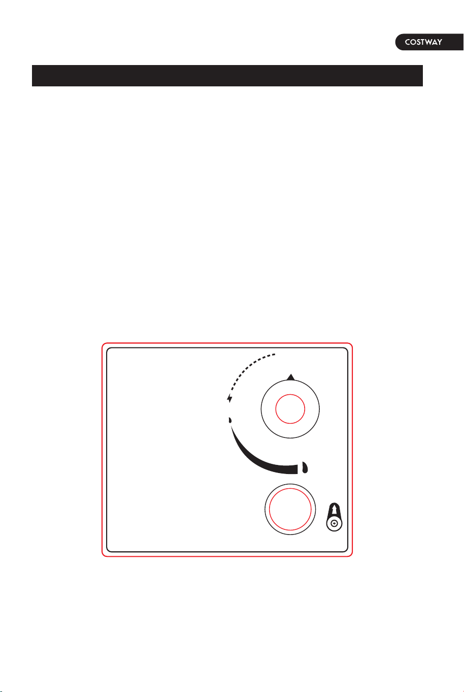
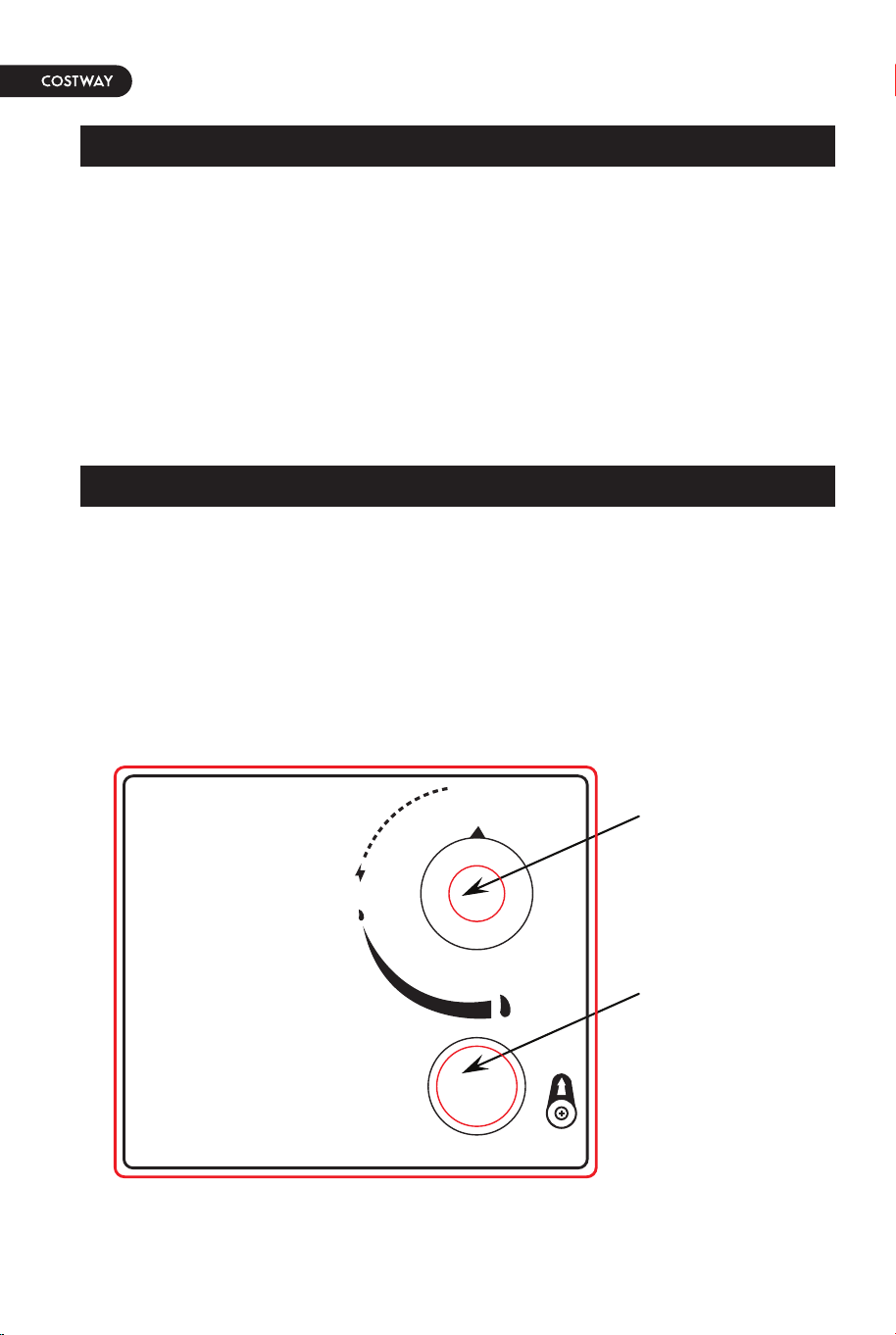
1. Push in gas control knob slightly and turn to “OFF”.
2. Turn gas control knob to “ON/MIN”.
3. Push in gas control knob all the way and hold. Continue to press
the ignition button for 15 seconds.
4. If the burner does not light in 15 seconds, release the knob and it
will pop back out. Wait 5 minutes before attempting to light the
burner again and repeat step 1 to 3.
WARNING: For your safety, read and follow the Lighting Instructions
in this manual and in the Rating Plate on the appliance. IMPROPER
LIGHTING PROCEDURES COULD RESULT IN A FIRE HAZARD OR
EXPLOSION HAZARD OR PROPERTY DAMAGE, INJURY OR LOSS OF
LIFE.
1. Push in gas control knob slightly and turn to “OFF”.
Figure 24
gas control knob
ignition button
LIGHTING INSTRUCTIONS
TO TURN OFF GAS
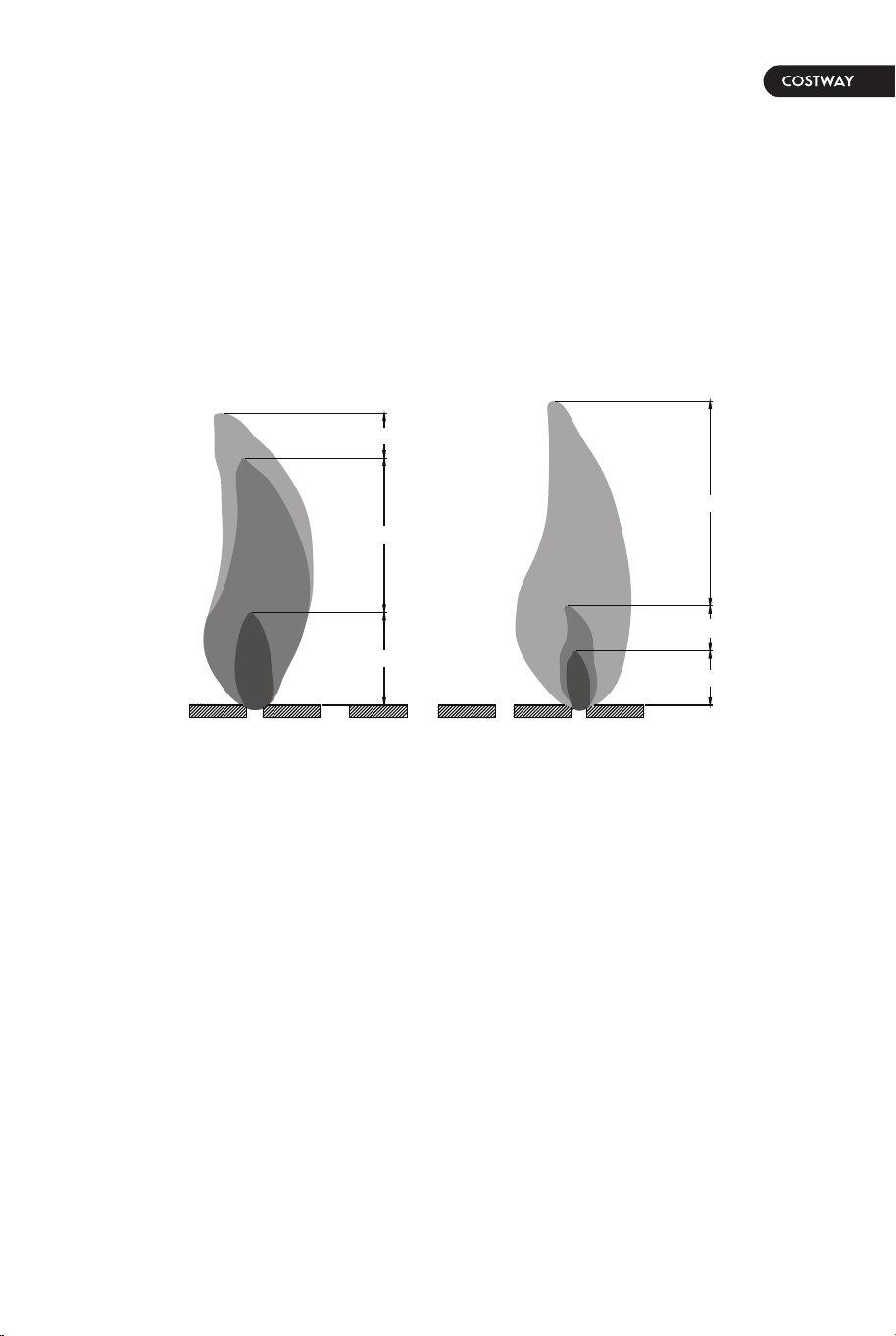
Observe Flame Height When Lit: The burner will display blue and
yellow flames. These flames should be a blue / yellow color between
1~2 in. height, (see Figure 25). These flames should not be yellow
or produce thick smoke. This would indicate an obstruction of airflow
through the burners. The flames should be blue with straight yellow
tops.
Figure 25
Yellow
Yellow
Light Blue
Light Blue
Blue
Blue
Good Bad
OFF
(APG.)
MAX
(MÁX.)
1 AAA
1.5V
IGNITOR
( Encendedor )
ON/MIN
(ENC./MÍN.)
LIGHTING INSTRUCTIONS
1. Push in gas control knob slightly and
2. Turn gas control knob to “ON/MIN”.
3. Push in gas control knob all the way
4. If the burner does not light in 15
1. Push in gas control knob slightly and turn to “OFF”.
TO TURN OFF GAS
INSTRUCCIONES DE ENCENDIDO
PARA CERRAR EL GAS
1. Presione ligeramente la perilla de control del gas y gírela a la
2. Gire la perilla de control del gas a “ENC/MÍN” (encendido/mínimo).
3. Presione la perilla de control del gas hasta el fondo y mantenga presionada.
4. Si el quemador no se enciende en 15 segundos, suelte la perilla y esta
encender el quemador nuevamente, repita los pasos 1 al 3.
1. Presione ligeramente la perilla de control del gas y gírela a la
turn to “OFF”.
and hold. Continue to press the
ignition button for 15 seconds.
seconds, release the knob and it will
pop back out. Wait 5 minutes before attempting
to light the burner again, repeat step 1 to 3.
posición “APG” (apagado).
Siga presionando el botón de encendido durante 15 segundos.
volverá a su posición hacia afuera. Espere 5 minutos antes de intentar
posición “APG” (apagado)
24 25
1. Push in gas control knob slightly and turn to “OFF”.
2. Turn gas control knob to “ON/MIN”.
3. Push in gas control knob all the way and hold. Continue to press
the ignition button for 15 seconds.
4. If the burner does not light in 15 seconds, release the knob and it
will pop back out. Wait 5 minutes before attempting to light the
burner again and repeat step 1 to 3.
WARNING: For your safety, read and follow the Lighting Instructions
in this manual and in the Rating Plate on the appliance. IMPROPER
LIGHTING PROCEDURES COULD RESULT IN A FIRE HAZARD OR
EXPLOSION HAZARD OR PROPERTY DAMAGE, INJURY OR LOSS OF
LIFE.
1. Push in gas control knob slightly and turn to “OFF”.
Figure 24
gas control knob
ignition button
LIGHTING INSTRUCTIONS
TO TURN OFF GAS
Observe Flame Height When Lit: The burner will display blue and
yellow flames. These flames should be a blue / yellow color between
1~2 in. height, (see Figure 25). These flames should not be yellow
or produce thick smoke. This would indicate an obstruction of airflow
through the burners. The flames should be blue with straight yellow
tops.
Figure 25
Yellow
Yellow
Light Blue
Light Blue
Blue
Blue
Good Bad
OFF
(APG.)
MAX
(MÁX.)
1 AAA
1.5V
IGNITOR
( Encendedor )
ON/MIN
(ENC./MÍN.)
LIGHTING INSTRUCTIONS
1. Push in gas control knob slightly and
2. Turn gas control knob to “ON/MIN”.
3. Push in gas control knob all the way
4. If the burner does not light in 15
1. Push in gas control knob slightly and turn to “OFF”.
TO TURN OFF GAS
INSTRUCCIONES DE ENCENDIDO
PARA CERRAR EL GAS
1. Presione ligeramente la perilla de control del gas y gírela a la
2. Gire la perilla de control del gas a “ENC/MÍN” (encendido/mínimo).
3. Presione la perilla de control del gas hasta el fondo y mantenga presionada.
4. Si el quemador no se enciende en 15 segundos, suelte la perilla y esta
encender el quemador nuevamente, repita los pasos 1 al 3.
1. Presione ligeramente la perilla de control del gas y gírela a la
turn to “OFF”.
and hold. Continue to press the
ignition button for 15 seconds.
seconds, release the knob and it will
pop back out. Wait 5 minutes before attempting
to light the burner again, repeat step 1 to 3.
posición “APG” (apagado).
Siga presionando el botón de encendido durante 15 segundos.
volverá a su posición hacia afuera. Espere 5 minutos antes de intentar
posición “APG” (apagado)

26 27
CARE AND MAINTENANCE
To enjoy the outstanding performance from your fire pit, make sure
you perform the following activities on a regular basis:
1. Use warm soapy water for cleaning. Never use flammable or
corrosive cleaning agents.
2. While cleaning the fire pit, make sure to keep the area around
the burner dry at all times. DO NOT submerge the control valve
assembly. If the gas control is submerge in water, DO NOT use it. It
must be replaced.
3. Air flow must be unobstructed. Keep controls, burner, and
circulating air passageways clean. Signs of possible blockage
include:
(1). Gas odor with extreme yellow tipping of flame.
(2). Fire pit does NOT reach the desired temperature.
(3). Fire pit flame is excessively uneven.
(4). Fire pit makes popping noises.
(5). Spiders and insects can nest in burner or orifice. This
dangerous condition can damage fire pit and render it unsafe for
use. Clean burner holes by using a heavy-duty pipe clearer.
Compressed air may help clear away small particles.
4. Carbon deposits may create a fire hazard. Clean burner with
warm soapy water if any carbon deposits develop.
5. Cover your fire pit with an outdoor weather cover when not in
use to protect it from the elements.
NOTE: Always allow fire pit to cool COMPLETELY before you cover
the fire pit with an outdoor weather cover or you attempt to service
or perform maintenance.
REPLACEMENT PARTS LIST
Back panel
A
B
C
D
E
F
G
H
I
J
K
L
M
N
F210103-TTA
F210020-FP
F210020-BP
F210020-RP
F210020-FRL
F210020-FLL
Right panel
Front-right leg
Front-left leg
F210020-BLL
Back-left leg
F210020-BRL
Back-right leg
F210020-GCS
Gas cylinder support
ANES-GV
Firepit gas valve
PF-FIREPIT-ROCK-132
Firepit lava rock (red)
PF-FIREPIT-TC-10
Firepit thermocouple, 250 mm/10"
PF-FIREPIT-LVL-ET-32
Firepit foot leveler 03, 32 x 23 mm
PF-FIREPIT-R180H14
Firepit regulator 180 degree hose 350 mm/14"
PF-FIREPIT-ET-S-W12
Firepit electrode 3" tip, wire 300 mm for
40000, 50000 BTU
PF-FIREPIT-PI
Firepit pulse ignition
PF-FIREPIT-KNOB-ET-L
Firepit control knob ET, large #6
F210020-WC
Weather cover
PF-FIREPIT-ET-HDL
Firepit door handle ET
PF-FIREPIT-GAS-418
Firepit orifice nature gas for 50000 BTU
Table top assembly
Front panel
F210020-DP
Door panel
NO
PART# DESCRIPTION
THIS INSTRUCTION BOOKLET CONTAINS IMPORTANT SAFETY INFORMATION. PLEASE READ AND KEEP FOR FUTURE REFERENCE.
EN
DE
FR
ES
IT
PL
With your inspiring rating, COSTWAY will be more consistent to offer you EASY
SHOPPING EXPERIENCE, GOOD PRODUCTS and EFFICIENT SERVICE!
Mit Ihrer inspirierenden Bewertung wird COSTWAY konsistenter sein, um Ihnen EIN
SCHÖNES EINKAUFSERLEBNIS, GUTE PRODUKTE und EFFIZIENTEN SERVICE zu
bieten!
Avec votre évaluation inspirante, COSTWAY continuera à fournir une EXPÉRIENCE
D’ACHAT PRATIQUE, des PRODUITS DE QUALITÉ et un SERVICE EFFICACE !
Con su calificación inspiradora, COSTWAY será más consistente para ofrecerle
EXPERIENCIA DE COMPRA FÁCIL, BUENOS PRODUCTOS y SERVICIO EFICIENTE.
Con la tua valutazione incoraggiante, COSTWAY sarà più coerente per offrirti
ESPERIENZA DI ACQUISTO FACILE, BUONI PRODOTTI e SERVIZIO EFFICIENTE!
Dzięki twojej opinii COSTWAY będzie mógł oferować jeszcze WYGODNIEJSZE
ZAKUPY, LEPSZE PRODUKTY i SPRAWNIEJSZĄ OBSŁUGĘ KLIENTA.
FIRE PIT
NP10464US
USER’S MANUAL
US office: Fontana UK office: Ipswich AU office: Truganina
DE office: Hamburg
FR office: Saint Vigor d'Ymonville
PL office: Gdańsk