1
Manufacturer reserves the right to discontinue, or change at any time, specifications or designs without notice and without incurring obligations.
Catalog No. 991-1000-01 11/2019
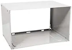
24-inch Wall Sleeve
for Through-The-Wall Air Conditioner
Installation Instructions
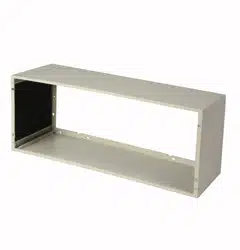
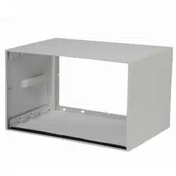
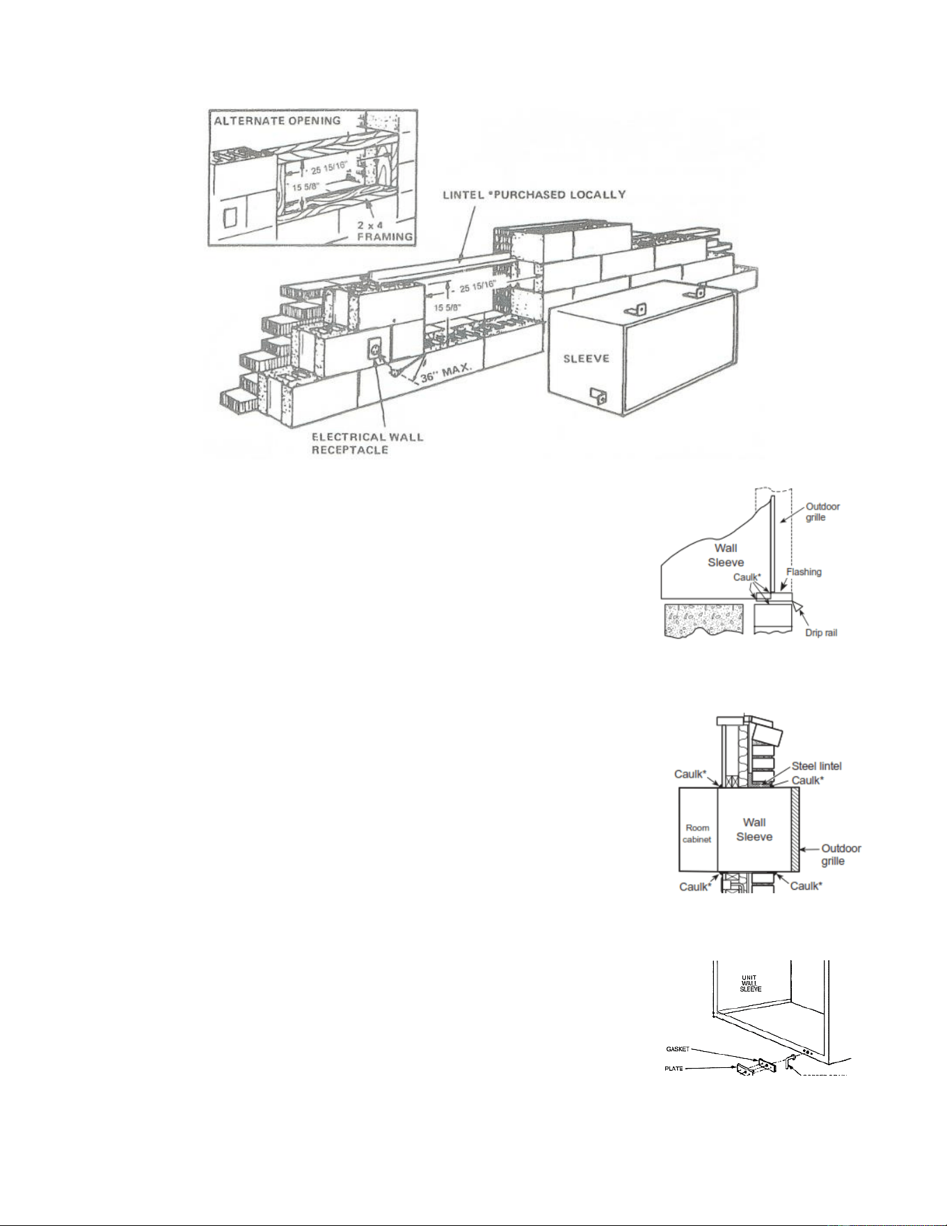
Wall Sleeve Overview - Figure 1
NOTE: Handle the wall sleeve carefully
SELECTING WALL LOCATION
Use the following guide for selecting the proper sleeve location which:
•
Should be located in an outside wall and contain no plumbing or electrical wiring.
•
Does not use wall sleeve to support major structural loads such as occur in frame construction at ends of windows, under
truss bearing points, etc.
•
Faces an unobstructed view to the area for which air conditioning is desired.
•
Is convenient to a suitable electrical outlet or where an additional outlet can be installed. The use of extension cords is not
recommended. Do not use an adapter plug.
2
Manufacturer reserves the right to discontinue, or change at any time, specifications or designs without notice and without incurring obligations.
Catalog No. 991-1000-01 11/2019
PREPARATION OF WALL
The wall sleeve should be installed during construction.
The wall sleeve will not support concrete block or brick. Lintels should be used
to support block or brick above the wall sleeve opening. For existing construction, wall openings must be framed out. The proper wall
opening is essential to avoid the necessity of fillers or additional framing. See Figure 2.
NOTE: Use lintel to support brick, block, etc., above the wall sleeve opening. (If directly under a window sill, the use of a lintel may not
be necessary.)
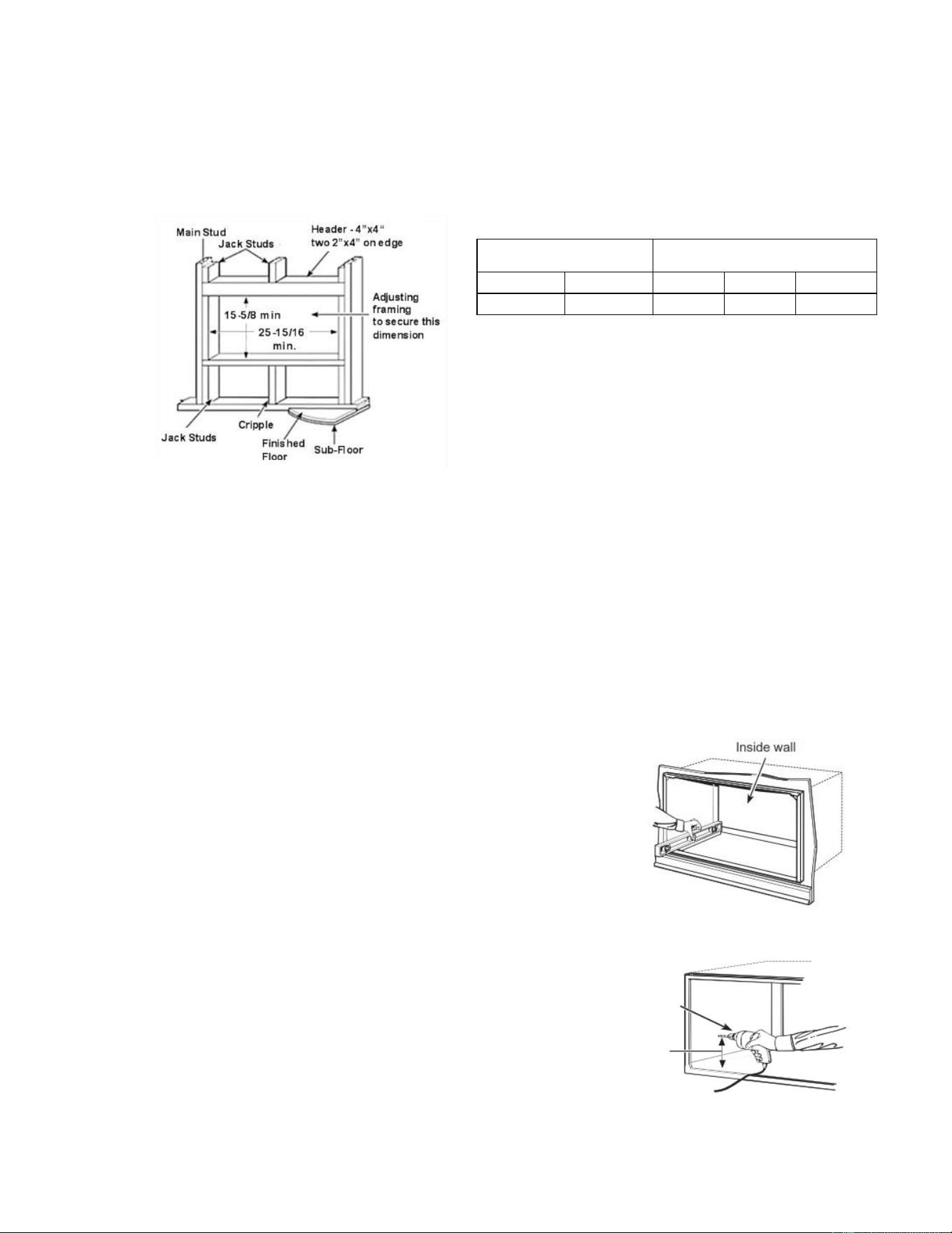
Minimum Finished
Opening Dimensions*
Wall Sleeve Dimensions
Height
Width
Height
Width
Depth
15 5/8-in
25 15/16-in
15 1/4-in
25 1/2-in
17 7/16-in
*Dimension may need to be increased to fit unique situations in the field
if using case angles.
INSTALLING WALL SLEEVE
OPTION 1 – INSTALLING WITHOUT MOUNTING ANGLES INTO WOOD/STEEL FRAMING
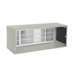
Remove front cover panel and center support tube. Retain front cover panel and support tube. Position the wall sleeve into the wall.
The rear (outside) edge of the wall sleeve should extend at least ¼ -inch beyond the outside wall to be able to caulk properly and prevent
sealing the drain holes in the rear flange of the sleeve, and to facilitate easy installation of an accessory drain, if desired. (if it is desired to
have the rear grille flush on the outside, a drip rail must be installed under the sleeve and caulking applied between the drip rail and sleeve.)
IMPORTANT:
Install wall sleeve level from side to side and with a slight tilt from front to rear as shown in Figure 3. Use a level; no more than a ¼
bubble will be the correct wall sleeve slant to the outside.
Firmly secure the wall sleeve to the wall structure using the existing holes on the sides and
top of sleeve or by drilling new holes in the appropriate location as shown in Figure 4. Do
NOT drill any holes in the bottom of the wall sleeve.
Drill 3/16-in. pilot holes and use a minimum #10 x 1-in. screws, lag bolt or appropriate
fasteners (Field Supplied) for the wall construction, to secure sleeve in place. It is
recommended that washers are used to prevent driving the screw head through the side
wall.
Drilling Mounting Holes – Figure 3
Only secure wall sleeve through the side and/or top. Do not drill any holes in the wall sleeve for
electrical connections.
Protect wall sleeve during construction from corrosive and acidic cleaning chemicals. These types
of cleaning chemicals will cause paint damage and premature rusting of the sleeve.
Drilling Mounting Holes – Figure 4
Typical Opening Overview - Figure 2
3
Manufacturer reserves the right to discontinue, or change at any time, specifications or designs without notice and without incurring obligations.
Catalog No. 991-1000-01 11/2019
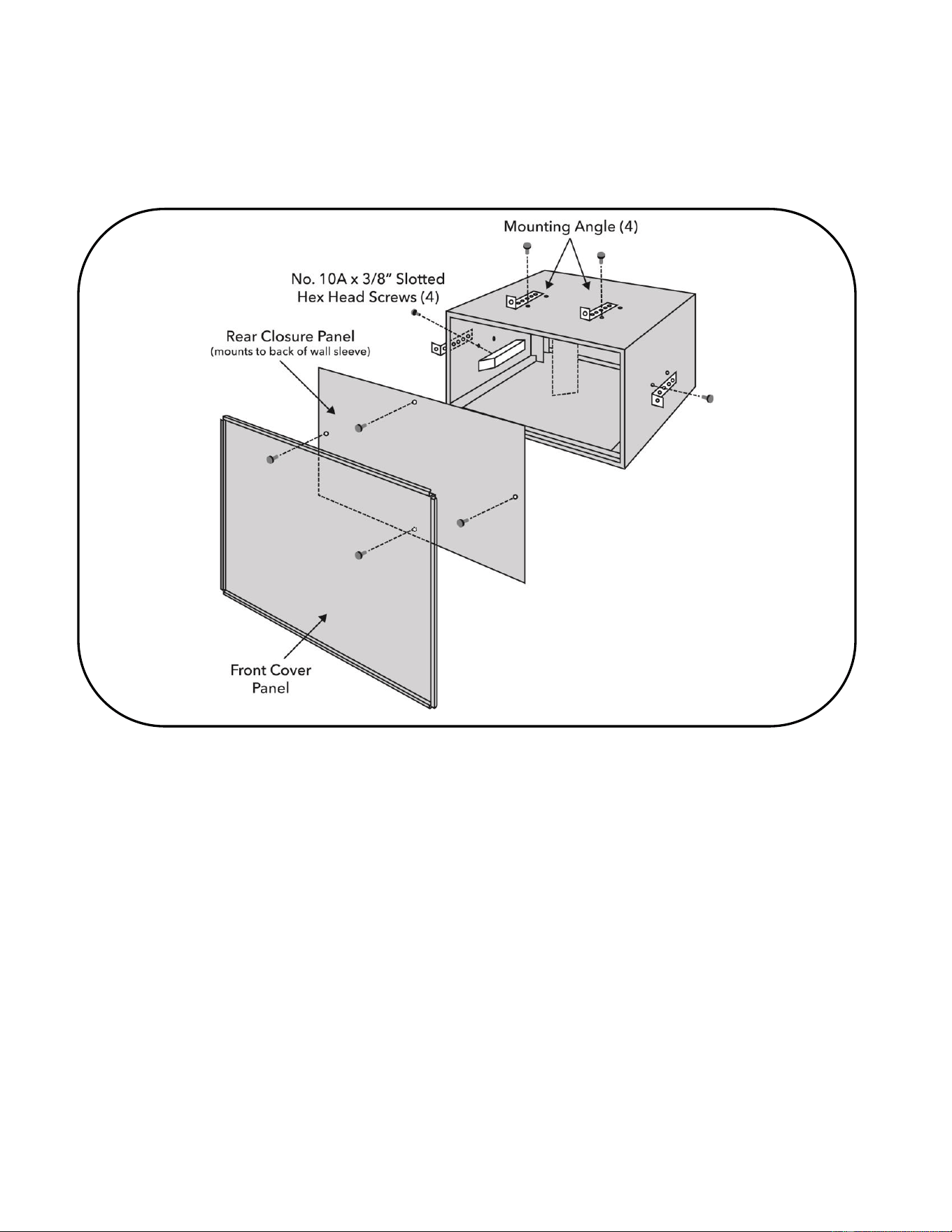
OPTION 2 - INSTALLLING INTO EXISTING WALL USING MOUNTING ANGLES
Use mounting angles provided for proper positioning of sleeve in framed wall opening (See Wall Sleeve Overview - Figure 1)
1.
Review the frame opening and minimum dimensions required for the type of wall construction (see figures 5, 6 & 7).
2.
Select either front or rear set of mounting holes on sleeve, which when aligned with one of the mounting angle holes, provides the
desired projection of the sleeve into room.
3.
Use screws (provided) to fasten angle brackets to wall sleeve. Use the same wall sleeve hole locations for each bracket.
Side mounting holes in sleeve are offset from top mounting holes to give sleeve proper pitch to outside.
4.
Install plastic hole plugs (provided) to seal unused mounting holes in wall sleeve.
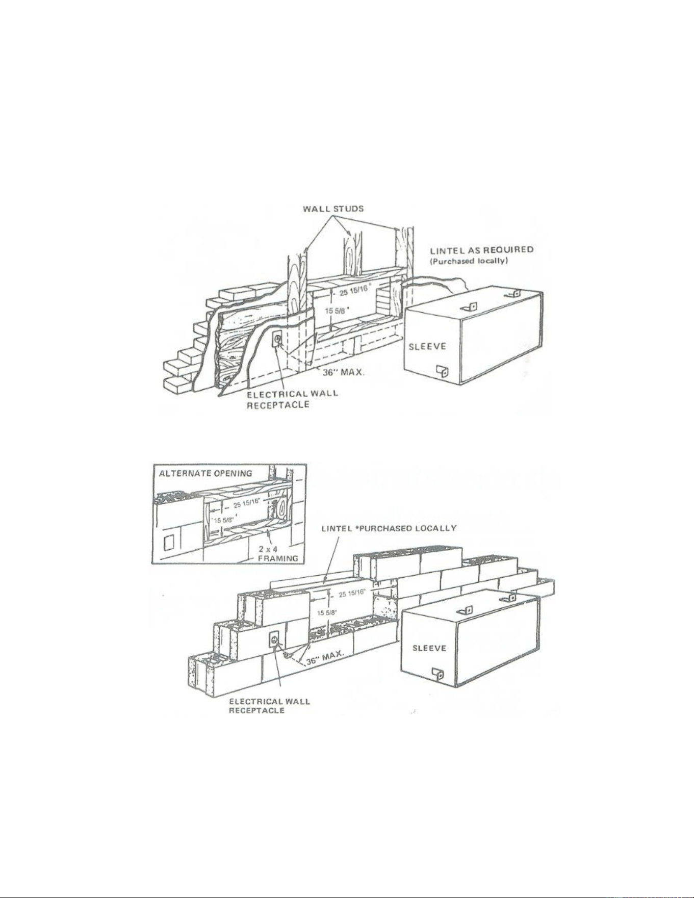
Frame Construction and Brick Veneer
Frame Construction and Brick Veneer- Figure 5
Solid Masonary Construction – Block
Masonary Installation - Figure 6
4
Manufacturer reserves the right to discontinue, or change at any time, specifications or designs without notice and without incurring obligations.
Catalog No. 991-1000-01 11/2019
Solid Masonary Construction - Brick and Block
Masonary and Brick Installation - Figure 7
For installation in extra thick walls
1.
The wall sleeve should not be installed in a thick wall where the wall sleeve is recessed
more than 3 inches from the exterior wall surface.
2.
If the wall sleeve is being recess 3 or less inches from the exterior wall sleeve, install
flashing under the wall sleeve. Extend the flashing up 2 inches on each side. The flashing
must include a drip rail as shown in figure 8.
WEATHERPROOFING
Re-install front panel, rear panel and center support tube to maintain maximum structural
rigidity until AC unit is installed. Weatherproof gaps between the wall sleeve and all exterior
and interior wall surfaces
as shown in Figure 9. Use a waterproof filler and sealant such as
caulk or equivalent weatherproofing sealant.
*NOTE
: It is critical to seal around all four sides of the wall sleeve, both on the outside and
the room side to prevent air and water infiltration.
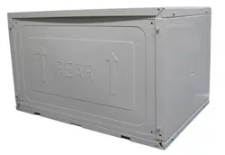
REAR GRILLE
Remove 4 screws holding rear weather barrier from the wall sleeve and install rear grille
according to instructions provided with the grille.
ELECTRICAL REQUIREMENTS
Provisions should be made to have the proper electrical outlet near the wall sleeve. All wiring
should be made in accordance with local codes and regulations. Prior to installation, verify
power cord will easily reach a wall receptacle. See the Unit Owner’s Manual for the type and
how to connect electrical supply.
DRAIN KIT (optional)
A drain tube can be added to the outside face of the wall sleeve to carry condensate water
away from the unit and the building. See figure 10. To install, see instructions included with
the drain kit.
Extra Thick Wall Installation – Figure 8
Weatherproofing Wall Sleeve – Figure 9
Condensate Drain – Figure 10