DO NOT remove the thermal insulation from sleeve.
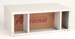
Standard Metal Wall Sleeve
Packaged Terminal Air Conditioner
Installation Instructions
INTRODUCTION
These instructions cover the installation of a
standard metal
wall
sleeve through masonry, steel or wood frame walls. Fasteners
are field supplied. Air conditioner and rear grille are shipped
separately.
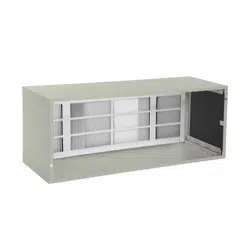
The sleeve is shipped unassembled. It must be field assembled
prior to installation.
A corrugated weather barrier is also included. If required, it can
be attached to the rear of the sleeve to provide temporary
weather protection.
PACKAGE CONTENTS
SELECTING LOCATION
Use the following guide for selecting the proper sleeve location:
1.
Allow at least 14 inches from front of sleeve for
removal of front panel and air conditioner for
maintenance.
2.
The sleeve may be installed flush against the floor
(including carpeting), except for installations using
subbase. See SUBBASE INSTALLATIONS section
below.
3.
For cord-connected air conditioners, an electrical
receptacle must be located within reach of power cord.
Table 1 shows typical power cord lengths from the
sleeve.
Table 1 — Standard Power Cord Length*
in. (mm)
VOLTAGE
TO LEFT OF SLEEVE
TO RIGHT OF SLEEVE
230/208v
18 (457)
36 (914)
265v
**
**
* Consult air conditioner manufacturer's specifications for actual power cord length.
**The 265-v cord will not extend beyond bottom of air conditioner
SUBBASE INSTALLATIONS
— When installing a
subbase to support the sleeve or for an electric receptacle for
the power cord, the sleeve must project 2
3
/
4
inches into the
room to have room for the subbase and receptacle box. The
sleeve must be installed between 3
1
/
4
to 5
1
/
2
inches (maximum)
above floor (including carpeting).
IMPORTANT: If sleeve projects more than 4 inches
into a room, manufacturer recommends a subbase or
leveling legs accessory to prevent the sleeve from
sagging or cantilevering into the room.
WALL PREPARATION
Proper attention to wall preparation, opening size and good
construction practices are essential to a trouble free sleeve
installation.
Wall Opening Size
—
Recommended minimum wall
opening is 42
1
/
4
in. wide x 16
1
/
8
in. high.
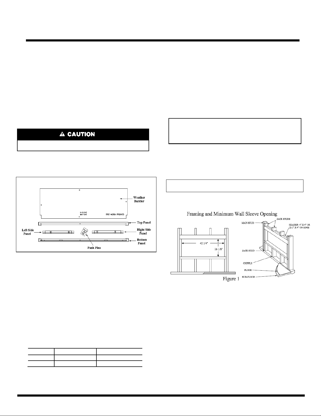
WOOD/STEEL FRAMING — Build a frame to the minimum
wall opening size to support the sleeve as shown in Figure 1.
MASONRY WALLS — Create the recommended minimum
wall opening, 42
1
/
4
in. wide x 16
1
/
8
in. high. The sleeve will not
support concrete block or bricks. Use proper sized lintels to
support block or bricks above wall opening. The sleeve should
be fastened to masonry walls with masonry screws (field
supplied). If the opening is framed in wood, use wood screws to
secure the sleeve.
CURTAIN WALL — Use case angles to create the
recommended minimum wall opening, 42
1
/
4
in. wide x 16
1
/
8
in.
high, for installations such as curtain walls, window walls, or
where the structural material of the wall is insufficient to support
or fasten the wall sleeve to. Case angles are pieces of steel or
similar material that are formed to a 90° angle. Add holes to
fasten the case angle to the sleeve and to the structural
component of the wall.
PACKAGE CONTENTS
Manufacturer reserves the right to discontinue, or change at any time, specifications or designs without notice and without incurring obligations.
Catalog No. FAP110-2000-01 Printed in U.S.A. Form SnapEase Metal Sleeve 4-27-2017 Pg 1
DO NOT remove the thermal insulation from sleeve.
Never drill or install fasteners through bottom of sleeve.
Protect wall sleeve during interior and exterior surface cleaning
from corrosive and acidic chemicals. These types of chemicals
will cause paint damage and premature rusting of the wall sleeve.
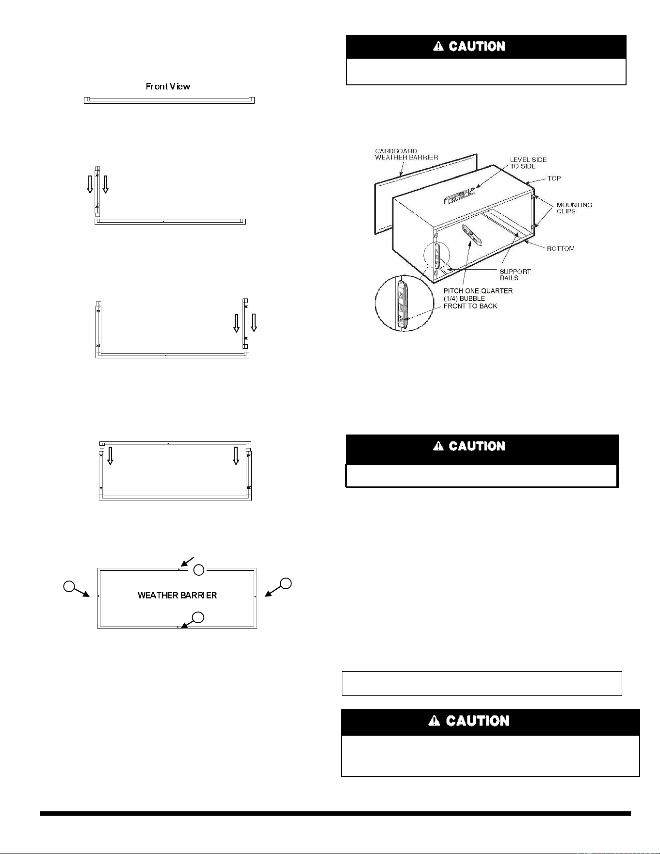
ASSEMBLE WALL SLEEVE
Step 1 Set Bottom Panel on a clean flat and level surface.
Step 2 Locate Left Side Panel. Align panel in the Left Bottom
Panel slot. Fully insert Left Panel into Bottom Panel until
locking tabs engage.
Front View
Step 3 Locate Right Side Panel. Align panel in the Right
Bottom Panel slot. Fully insert Right Panel into Bottom Panel
until locking tabs engage.
Front View
Step 4 Locate Top Panel and align with top of Right and
Left Side Panels. Fully insert Top Panel into Right and Left
Side Panels until locking tabs engage.
Front View
Step 5 (If required) Locate Weather Barrier and attach to the
rear of the assembled sleeve with four (4) supplied push pins.
Rear View
SLEEVE INSTALLATION
Step 1 Prepare Sleeve —
If grille is to be installed at this time,
remove and discard weather barrier panel and install rear grille per
the manufacturer's instructions. If condensate drain tube is to be
installed at this time, install per the manufacturer's instructions.
Step 2 Setting Sleeve —
Position the fully assembled sleeve in
the wall opening with the bottom down and the drain holes
toward the outdoors.
Sleeve must extend at least
5
/
8
inches beyond building exterior to
assure proper drainage and to allow weather tight seal. Sleeve must
extend at least
1
/
4
inches into room for proper weatherproofing.
Step 3 Leveling Sleeve
—
Place level in locations shown
in Figure 2. Sleeve must be mounted level side to side and a
1/4 bubble tilt front to back. Use shims as required to insure
proper level. This will allow for proper condensate drainage.
Step 4 Fastening Sleeve to Wall
—
Locate and mark
two (2) holes on each side approximately 4-inches from the
bottom and 4-inches from the top.
Drill 3/16-in. pilot holes and use #10 x 1-in. screws, or
appropriate fasteners for the wall construction, to secure
sleeve in place. It is recommended that washers are used to
prevent driving the screw head through the side wall.
Check the sleeve is level side to side and a 1/4 bubble tilt
front to back. Adjust if necessary. See Figure 2.
Step 5 Exterior Weather Proofing —
Proper weather
proofing of all sides between the wall surface and sleeve is
essential to assure a trouble-free installation.
Apply sealant, caulking or equivalent weather proofing
material around the perimeter of the sleeve to eliminate
outdoor air and water leaks into the room.
Step 6 Interior Weather Proofing —
Apply sealant,
caulking or equivalent weather proofing material to joints
around the perimeter ( including bottom) of the sleeve to
create a total air seal.
Note
: Expandable foam insulation may be added to fill large
wall gaps. Apply per manufacturer's instructions.
4
1
3
1
2
1
1
Figure 2
Manufacturer reserves the right to discontinue, or change at any time, specifications or designs without notice and without incurring obligations.
Catalog No. FAP110-2000-01 Printed in U.S.A. Form SnapEase Metal Sleeve 4-27-2017 Pg 2