Loading ...
Loading ...
Loading ...
INSTRUCTION SHEET
©2021 Electrolux Home Products, Inc. Instruction Sheet A00343905 7.23.21
Frigidaire TRMKTEZ1FL79 Side Trim Attachment Setup
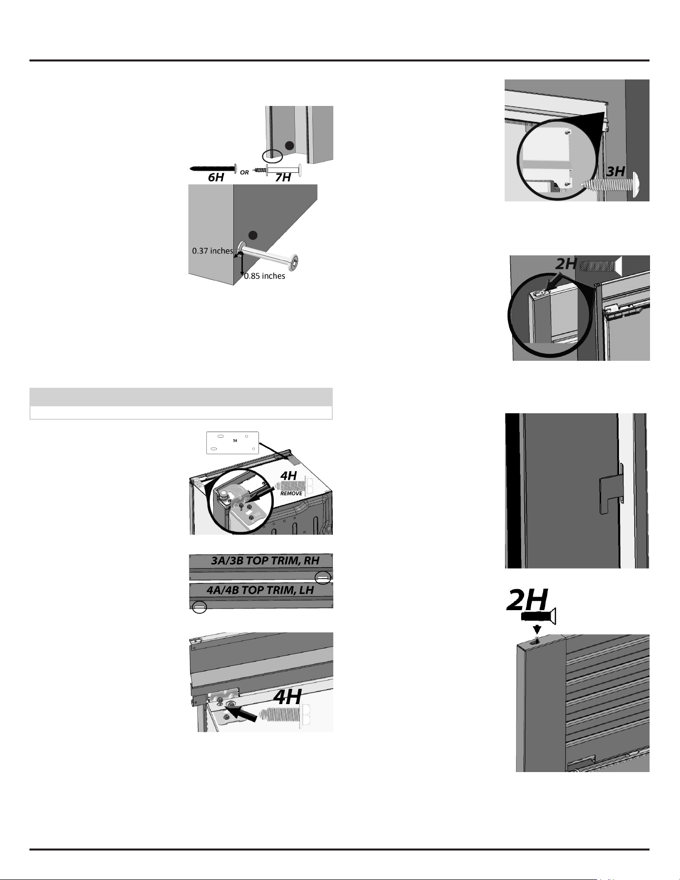
6. Depending on which long
screw you received (6H or
7H) screw a long screw in
the lower left area (Fig. 9A)
of the front cabinet space,
approximately in the location
described in Fig. 9B.
7. Repeat step 6 for the right
side of the cabinet using the
other 6H/7H screw.
A
B
Fig. 9
Power and Water Line Connection
Note: Refer to the Use & Care Manual for power requirements and water
supply hookup before proceeding. Find Service Kit TTFLTRICEKIT at
ElectroluxAppliances.com for connecting the water line and filtering ice.
Top Trim Attachment
NOTE
You will need a step ladder to install top trim components.
8. a. Remove the front outer
screw from the top hinge
(Fig. 10) using a
5
/
16
”
socket driver or wrench
and save for later. Locate
bracket 1H and place it
on the top of the unit to
be used on Step 14.
b. Roll the unit into the
cabinet roughly of the
way in, ensuring the
product is centered in the
cabinet cutout.
c. Choose the top trim
according to which side
the door hinge is on
(Fig. 11). You do not need
the other Top Trim for
the installation.
d. Install the Top Trim by
fastening two 4H screws
along the base of the
trim with a
5
/
16
” socket
wrench (Fig. 12). Screw
through the 1H bracket in
step 8a to properly level
the Top Trim.
Fig. 10
Fig. 11
Fig. 12
9. a. Slide the unit into place,
and ensure the dual
installation is centered.
b. Drill
1
/
8
” pilot holes and
fasten two 3H screws
on the right side of the
Top Trim with a Phillips
screwdriver to cabinets
(Fig. 13).
c. Repeat for the left side.
Fig. 13
Frigidaire TRMKTEZ1FL79 Side Trim Installation
10. a. Place the Side Trims in
position by dropping
them over the placement
screw as seen in Fig. 9
and fitting them over the
Top Trim (Fig. 14).
b. Fasten a 2H screw to
each side of the Top Trim
(Fig. 14).
Fig. 14
Electrolux TRMKTSS1LV84 Side Trim Installation
11. a. Slide the left Side Trim into
place by carefully guiding
the Side Trim hooks
through the Side Trim
Attachment slots. Fig. 15
shows an inside view.
Fig. 15
b. Fasten 2H screws to
the Top Trim (Fig. 16)
and repeat for the right
hand side.
Fig. 16
Loading ...