Loading ...
Loading ...
Loading ...
6
7
8
8.1
A
B
G
F
A
D
CE
A
B
G
C
E
A
F
D
A
B
C
D
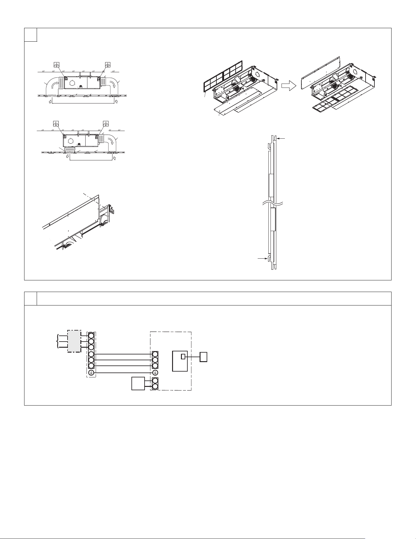
[Fig. 7-0-1]
[Fig. 7-0-2]
[Fig. 7-0-3]
[Fig. 7-0-4]
A Duct
B Air inlet
C Access door
D Canvas duct
E Ceiling surfas
F Air outlet
G Leave distance enough to
prevent short cycle
<A> In case of rear inlet
<B> In case of bottom inlet
A Filter
B Bottom plate
C Nail for the bottom inlet
D Nail for the rear inlet
S1
S2
L1
L2
G
1
2
S1
S2
S3
CN105
RED
S3
AB
C
D
E
G
H
F
[Fig. 8-1-1]
A Outdoor unit power supply
B Isolating switch
C Outdoor unit
D Indoor unit/outdoor unit connecting cords
E Wired remote controller
F Indoor unit
G Indoor controller board
H Radio frequency interface for RF thermostat
KJ79P806H01.book 6 ページ 2021年12月13日 月曜日 午後2時15分
Loading ...
Loading ...
Loading ...