Loading ...
Loading ...
Loading ...
19
9. Test run
9.2. Test run
9.2.1. Using wired remote controller
Make sure to read operation manual before test run. (Especially items to secure safety)
• Remote controller: The system will go into startup mode, and the remote controller power lamp (green) and “PLEASE WAIT” will blink. While the lamp and message are
blinking, the remote controller cannot be operated. Wait until “PLEASE WAIT” is not displayed before operating the remote controller. After the power is turned on, “PLEASE
WAIT” will be displayed for approximately 2 minutes.
• Indoor controller board: LED 1 will be lit up, LED 2 will be lit up (if the address is 0) or off (if the address is not 0), and LED 3 will blink.
• Outdoor controller board: LED 1 (green) and LED 2 (red) will be lit up. (After the startup mode of the system finishes, LED 2 will be turned off.) If the outdoor controller board
uses a digital display, [- ] and [ -] will be displayed alternately every second.
If the operations do not function correctly after the procedures in step 2 and thereafter are performed, the following causes should be considered and eliminated if they are
found.
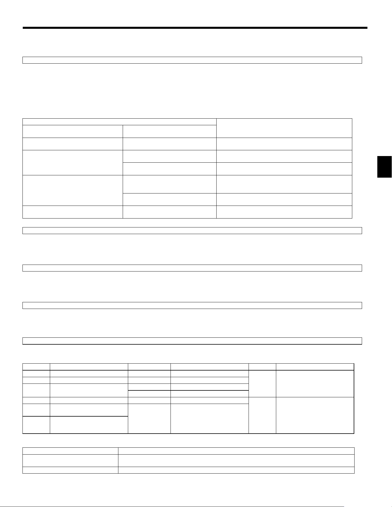
(The symptoms below occur during the test run mode. “Startup” in the table means the LED display written above.)
1Select “Test run” from the Service menu, and press the [SELECT] button. [Fig. 9-2-1] (P.9)
2Select “Test run” from the Test run menu, and press the [SELECT] button. [Fig. 9-2-2] (P.9)
3The test run operation starts, and the Test run operation screen is displayed.
1Press the [F1] button to change the operation mode. [Fig. 9-2-3] (P.9)
Cooling mode: Check that cool air blows from the unit.
Heating mode: Check that warm air blows from the unit.
The speed of the outdoor unit fan is controlled in order to control the performance of the unit. Depending on the ambient air, the fan will rotate at a slow speed and will keep
rotating at that speed unless the performance is insufficient. Therefore, the outdoor wind may cause the fan to stop rotating or to rotate in the opposite direction, but this is not a
problem.
1Press the [ON/OFF] button to stop the test run. (The Test run menu will appear.)
Note: If an error is displayed on the remote controller, see the table below.
• See the table below for the details of the LED display (LED 1, 2, and 3) on the indoor controller board.
Note:
If the unit is operated continuously during a test run, the unit stops after 2 hours.
Step 1 Turn on the power.
Symptoms in test run mode
Cause
Remote Controller Display
OUTDOOR BOARD LED Display
< > indicates digital display.
Remote controller displays “PLEASE WAIT”, and
cannot be operated.
After “startup” is displayed, only green lights
up. <00>
• After power is turned on, “PLEASE WAIT” is displayed for 2
minutes during system startup. (Normal)
After power is turned on, “PLEASE WAIT” is
displayed for 3 minutes, then error code is
displayed.
After “startup” is displayed, green (once) and
red (once) blink alternately. <F1>
• Incorrect connection of outdoor terminal block (R, S, T and S
1
, S
2
,
S
3
.)
After “startup” is displayed, green (once) and
red (twice) blink alternately. <F3, F5, F9>
• Outdoor unit’s protection devise connector is open.
No display appears even when remote controller
operation switch is turned on. (Operation lamp
does not light up.)
After “startup” is displayed, green (twice) and
red (once) blink alternately. <EA. Eb>
• Incorrect wiring between the indoor and outdoor unit (Polarity is
wrong for S
1
, S
2
, S
3
.)
• Remote controller transmission wire short.
After “startup” is displayed, only green lights
up. <00>
• There is no outdoor unit of address 0. (Address is other than 0.)
• Remote controller transmission wire open.
Display appears but soon disappears even when
remote controller is operated.
After “startup” is displayed, only green lights
up. <00>
• After canceling function selection, operation is not possible for
about 30 seconds. (Normal)
Step 2 Switch the remote controller to “Test run”.
Step 3 Perform the test run and check the airflow temperature and auto vane.
Step 4 Confirm the operation of the outdoor unit fan.
Step 5 Stop the test run.
LCD Description of malfunction LCD Description of malfunction LCD Description of malfunction
P1 Intake sensor error P9 Pipe sensor error (dual-wall pipe)
E0 – E5
Communication error between the
remote controller and the indoor unit
P2 Pipe sensor error (liquid pipe) PA Leakage error (refrigerant system)
P4
Drain float switch connector
disconnected (CN4F)
PB (Pb) Indoor unit fan motor error
PL Refrigerant circuit abnormal
P5 Drain overflow protection operation FB Indoor controller board error
E6 – EF
Communication error between the
indoor unit and the outdoor unit
P6
Freezing/overheating protection
operation
U*, F*
(* indicates an
alphanumeric
character excluding
FB.)
Outdoor unit malfunction
Refer to the wiring diagram for the
outdoor unit.
P8 Pipe temperature error
LED1 (microcomputer power supply) Indicates whether control power is supplied. Make sure that this LED is always lit.
LED2 (remote controller power supply)
Indicates whether power is supplied to the wired remote controller. The LED is lit only for the indoor unit that is
connected to the outdoor unit that has an address of 0.
LED3 (indoor/outdoor unit communication) Indicates whether the indoor and outdoor units are communicating. Make sure that this LED is always blinking.
KJ79P806H01.book 19 ページ 2021年12月13日 月曜日 午後2時15分
Loading ...
Loading ...
Loading ...