Loading ...
Loading ...
Loading ...
13
5. Installing the unit
5.1. Hanging the unit body
Bring the indoor unit to an installation site as it is packed.
To hang the indoor unit, use a lifting machine to lift and pass through the
hanging bolts.
[Fig. 5-1-1] (P.3)
[Fig. 5-1-2] (P.3)
5.2. Confirming the unit’s position and fixing hanging
bolts
Ensure that the hanging bolt nuts are tightened to fix the hanging bolts.
To ensure that drain is discharged, be sure to hang the unit at level using a
level.
Caution:
Install the unit in horizontal position. If the side with drain port is installed
higher, water leakage may be caused.
6. Refrigerant piping work
6.1. Refrigerant pipe
[Fig. 6-1-1] (P.3)
Refer to the Instruction Manual that came with the outdoor unit for the restrictions on
the height difference between units and for the amount of additional refrigerant
charge.
Avoid the following places for installation where air conditioner trouble is liable to occur.
• Where there is too much oil such as for machine or cooking.
• Salty environment as seaside areas.
• Hot-spring areas.
• Where sulfide gas exists.
• Other special atmospheric areas.
• This unit has flared connections on both indoor and outdoor sides. [Fig. 6-1-1]
• Refrigerant pipes are used to connect the indoor and outdoor units as shown in the
figure below.
• Insulate both refrigerant and drainage piping completely to prevent condensation.
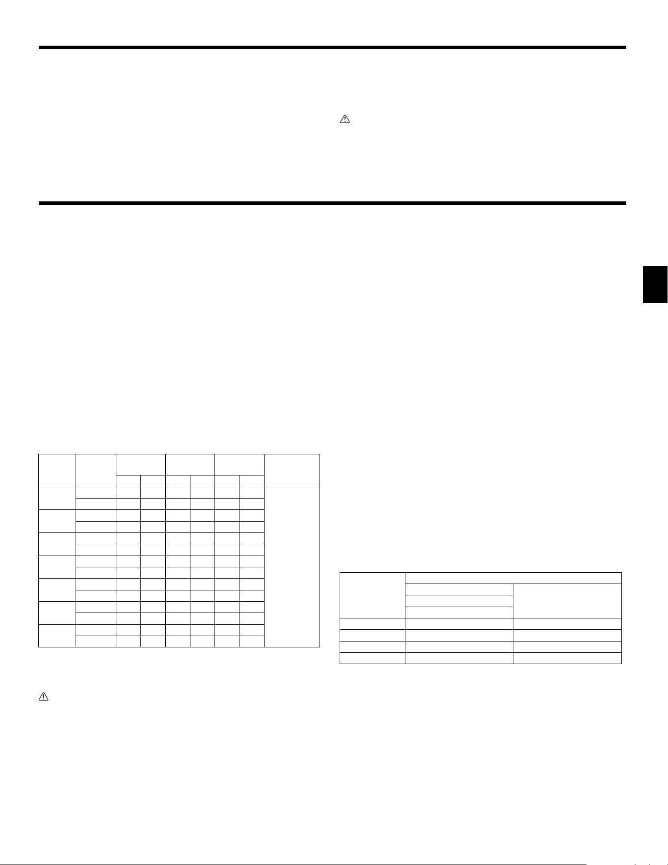
Piping preparation
• Refrigerant pipes of 3, 5, 7, 10 and 15 m [9-13/16, 16-3/8, 22-15/16, 32-1/4 and
49-3/16 ft] are available as optional items.
(1)Table below shows the specifications of pipes commercially available.
(2)Ensure that the 2 refrigerant pipes are well insulated to prevent condensation.
(3)Refrigerant pipe bending radius must be 10 cm [3-15/16 in] or more.
Caution:
Using careful insulation of specified thickness. Excessive thickness prevents
storage behind the indoor unit and smaller thickness causes dew drippage.
6.2. Flaring work
• Main cause of gas leakage is defect in flaring work.
Carry out correct flaring work in the following procedure.
6.2.1. Pipe cutting
[Fig. 6-2-1] (P.4)
• Using a pipe cutter cut the copper tube correctly.
6.2.2. Burrs removal
[Fig. 6-2-2] (P.4)
• Completely remove all burrs from the cut cross section of pipe/tube.
• Put the end of the copper tube/pipe to downward direction as you remove burrs in
order to avoid burrs drop in the tubing.
6.2.3. Putting nut on
[Fig. 6-2-3] (P.4)
• Remove flare nuts attached to indoor and outdoor unit, then put them on pipe/tube
having completed burr removal.
(not possible to put them on after flaring work)
6.2.4. Flaring work
[Fig. 6-2-4] (P.4)
• Carry out flaring work using flaring tool as shown below.
Firmly hold copper tube in a die in the dimension shown in the table at above.
6.2.5. Check
[Fig. 6-2-5] (P.4)
• Compare the flared work with a figure in right side hand.
• If flare is noted to be defective, cut off the flared section and do flaring work again.
A Unit body
B Lifting machine
C Nuts (field supply)
D Washers (accessory)
E M10 hanging bolt (field supply)
a Indoor unit
b Outdoor unit
Model Pipe
Outside
diameter
Min wall
thickness
Insulation
thickness
Insulation
material
mm inch mm inch mm inch
PEAD-
A09AA8
For liquid 6.35 1/4 0.8 1/32 8 5/16
Heat resisting
foam plastic
0.045 specific
gravity
For gas 9.52 3/8 0.8 1/32 8 5/16
PEAD-
A12AA8
For liquid 6.35 1/4 0.8 1/32 8 5/16
For gas 12.7 1/2 0.8 1/32 8 5/16
PEAD-
A15AA8
For liquid 6.35 1/4 0.8 1/32 8 5/16
For gas 12.7 1/2 0.8 1/32 8 5/16
PEAD-
A18AA8
For liquid 6.35 1/4 0.8 1/32 8 5/16
For gas 12.7 1/2 0.8 1/32 8 5/16
PEAD-
A24AA8
For liquid 9.52 3/8 0.8 1/32 8 5/16
For gas
15.88
5/8 1.0 1/32 8 5/16
PEAD-
A30AA8
For liquid 9.52 3/8 0.8 1/32 8 5/16
For gas
15.88
5/8 1.0 1/32 8 5/16
PEAD-
A36AA8
For liquid 9.52 3/8 0.8 1/32 8 5/16
For gas
15.88
5/8 1.0 1/32 8 5/16
a Copper tubes
b Good
c No good
d Tilted
e Uneven
f Burred
a Burr
b Copper tube/pipe
c Spare reamer
d Pipe cutter
a Flare nut
b Copper tube
a Flaring tool
b Die
c Copper tube
d Flare nut
e Yoke
Pipe diameter
(mm [in])
Dimension
A (mm [in])
B (mm [in])
When the tool for R410A is used
Clutch type
6.35 [1/4] 0 to 0.5 [0 to 1/32] 9.1 [3/8]
9.52 [3/8] 0 to 0.5 [0 to 1/32] 13.2 [17/32]
12.7 [1/2] 0 to 0.5 [0 to 1/32] 16.6 [21/32]
15.88 [5/8] 0 to 0.5 [0 to 1/32] 19.7 [25/32]
a Smooth all around b Inside is shining without any scratches
c Even length all around d Too much
e Tilted f Scratch on flared plane
g Cracked h Uneven
i Bad examples
+0
-0.4 [-1/32]
KJ79P806H01.book 13 ページ 2021年12月13日 月曜日 午後2時15分
Loading ...
Loading ...
Loading ...