Loading ...
Loading ...
Loading ...
4
6
6.2
6.3
d
c
b
a
b
a
a
b
e
b
c
d
c
A
c
b
a
defgh
i
B
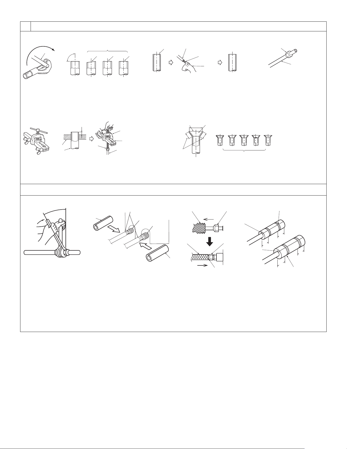
[Fig. 6-2-1] [Fig. 6-2-2] [Fig. 6-2-3]
[Fig. 6-2-4] [Fig. 6-2-5]
a
d
cb
ef
90°
a Copper tubes d Tilted
b Good e Uneven
c No good f Burred
a Smooth all around d Too much g Cracked
b Inside is shining without any scratches e Tilted h Uneven
c Even length all around f Scratch on flared plane i Bad examples
a Flaring tool d Flare nut
b Die e Yoke
c Copper tube
a Flare nut
b Copper tube
a Burr c Spare reamer
b Copper tube/pipe d Pipe cutter
A
B
C
D
F
G
E
O
O
N
N
20
[25/32]
20
[25/32]
20
[25/32]
20
[25/32]
H
H
K
L
J
I
J
[Fig. 6-3-2][Fig. 6-3-1]
A Pipe cover (small) (accessory)
B Caution:
Pull out the thermal insulation on the refrigerant piping at the site,
insert the flare nut to flare the end, and replace the insulation in its
original position.
Take care to ensure that condensation does not form on exposed
copper piping.
C Liquid end of refrigerant piping
D Gas end of refrigerant piping
E Site refrigerant piping
F Main body
G Pipe cover (large) (accessory)
H Thermal insulation (field supply)
I Pull
J Flare nut
K Return to original position
L Ensure that there is no gap here
M Plate on main body
N Band (accessory)
O Ensure that there is no gap here. Place join upwards.
(Unit: mm [in])
KJ79P806H01.book 4 ページ 2021年12月13日 月曜日 午後2時15分
Loading ...
Loading ...
Loading ...