Compatible VIVOTEK Cameras
I
Type Compatible cameras/brackets Brackets
A AM-212/221,
SD8363E, SD8364E, SD83x4E, SD83x6E, SD8333E,
w/ AM-519 (900014900G )
AM-311/411/711
B AE2000/ AE234/ 235/ 211/ 232/ 233 AM-311/411/711
C Medium Bullet, see below for compatibility. AM-311/411
D Large Bullet, see below for compatibility. AM-311/411
Revison History:
Rev. 1.0: Initial release
AM-311 Support List
Large Bullet Medium Bullet Ball swivel bracket
V03: 900002902G
IP8371E IP8335H
IP8372 IP8362
IB8373-EH
IP8355EH
IP8365EH
V04: 900002903G (V04 is backward compatible with the bullets supported by V03)
IB8381-E IP8364-C
IP8337H-C
IB8354-C
IB8367(-R)
IB8338-H(R)
Corresponding part numbers:
AM-311: 900002902G (v03)
900002903G (v04)
AM-711: 900005100G
AM-221: 900014800G
AM-212: 900004202G
VIVOTEK Mounting Accessories
AM-311 Pole mount
Installation Guide
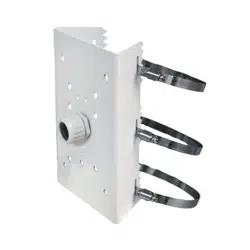
Package Contents
Items 1. Pole mount bracket, 2. Stainless belts, 3. M8X25mm screws, 4.
M6X35mm screws, 5. M6X20mm screws, 6. M4X15mm screws, 7. Silicone
seal plugs, 8. Waterproof corrugated tube ttings
Box Net Weight 1.4 kgs
Box Gross Weight 1.66 kgs
Box Dimensions 185 x 265 x 115mm
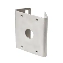
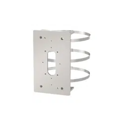
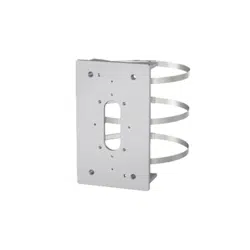
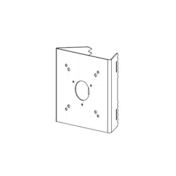
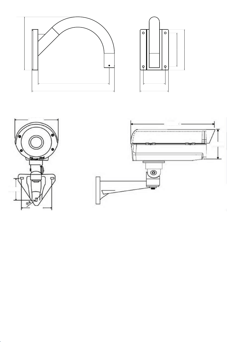
AM-311 Pole mount bracket
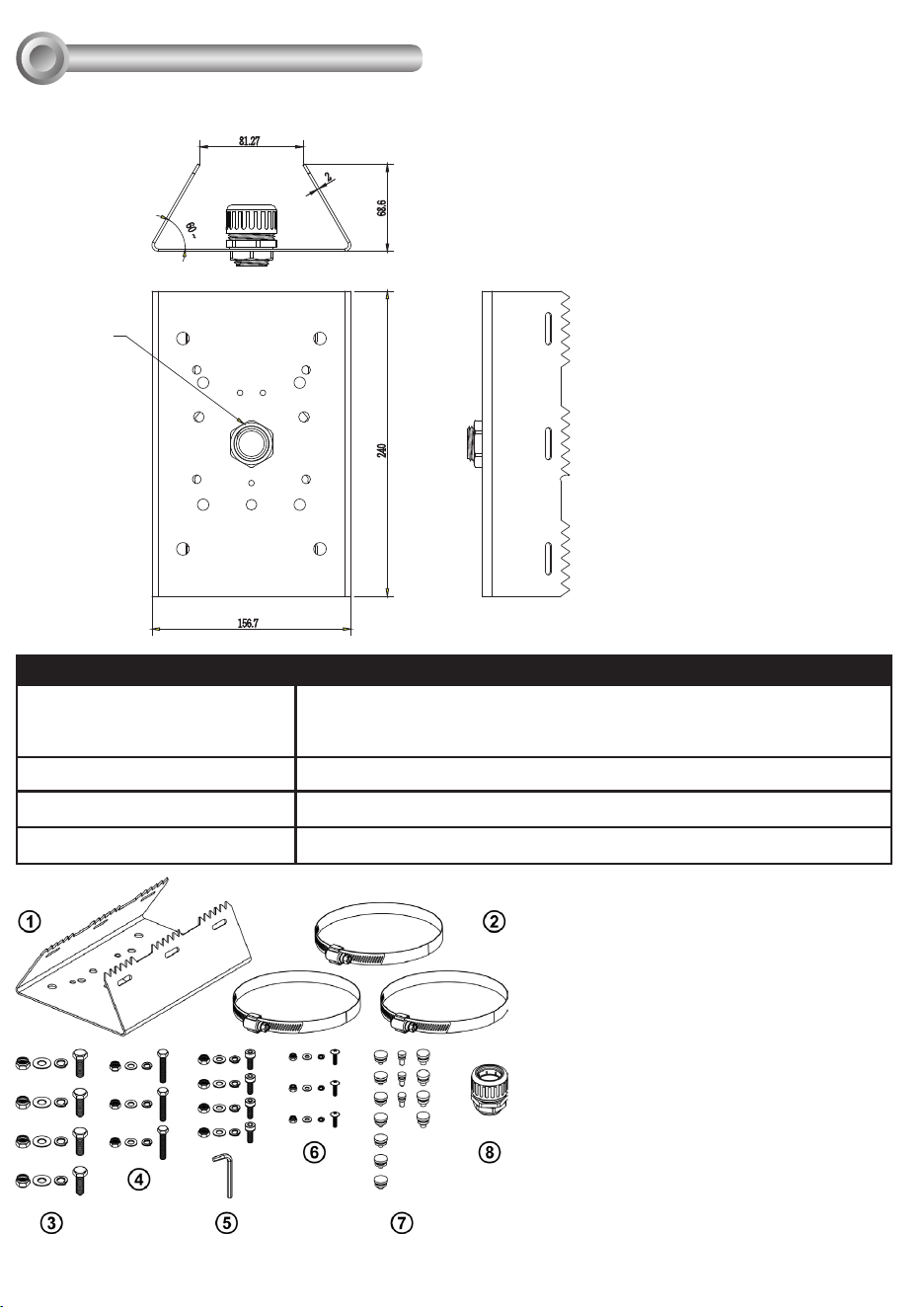
Mechanical Drawings
II
240
156.7
68.6
2
60
~
81.27
3/4" cable gland
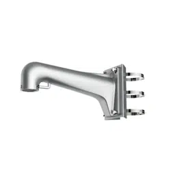
AM-221 Gooseneck
405.8
262.19
140
350 107.8
165.5
200
AE20xx Series Enclosure
160mm
68.5mm
83.2mm
425mm
165mm
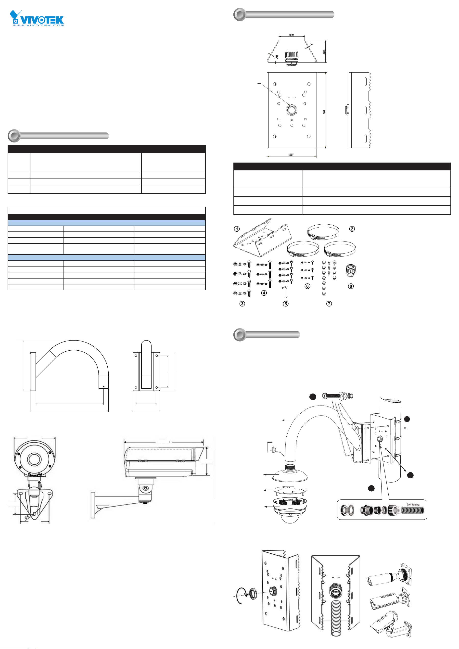
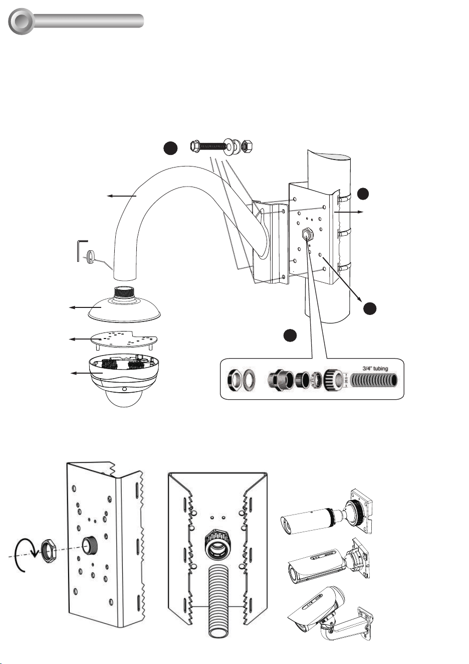
Installation
III
III-1. Pole mount installation: AM-311 & AM-221
Below is a general, sample procedure using a Pole mount bracket:
1. Route power lines and other cables through the included cable gland, pass them through conduits (separately
purchased), and install the cable gland to the pole mount bracket.
2. Locate the position where you want to install the pole mount bracket and camera. Unwrap the stainless belts,
feed them through the openings on the sides of the bracket, and then strap them around the pole. Use a pincer
and athead screwdriver to fasten the bracket to the pole.
3. Fill the unused screw holes using the included silicone stoppers.
1
2
3
4
4. Secure the gooseneck bracket using the included hex bolts, washers, and nuts.
The sample here utilizes the AM-518 bracket for a xed dome camera. Please refer to the AM-518/51A
Installation Guide for other options.
Gooseneck
bracket
Mounting
adapter
Dome
camera
Mounting
plate
Pole mount
bracket
Cable gland and 3/4" conduits
NOTE: Do not apply the cable gland when
using the following camera types:
Ball-swivel
bracket
Large bullet
Compatible VIVOTEK Cameras
I
Type Compatible cameras/brackets Brackets
A AM-212/221,
SD8363E, SD8364E, SD83x4E, SD83x6E, SD8333E,
w/ AM-519 (900014900G )
AM-311/411/711
B AE2000/ AE234/ 235/ 211/ 232/ 233 AM-311/411/711
C Medium Bullet, see below for compatibility. AM-311/411
D Large Bullet, see below for compatibility. AM-311/411
Revison History:
Rev. 1.0: Initial release
AM-311 Support List
Large Bullet Medium Bullet Ball swivel bracket
V03: 900002902G
IP8371E IP8335H
IP8372 IP8362
IB8373-EH
IP8355EH
IP8365EH
V04: 900002903G (V04 is backward compatible with the bullets supported by V03)
IB8381-E IP8364-C
IP8337H-C
IB8354-C
IB8367(-R)
IB8338-H(R)
Corresponding part numbers:
AM-311: 900002902G (v03)
900002903G (v04)
AM-711: 900005100G
AM-221: 900014800G
AM-212: 900004202G
VIVOTEK Mounting Accessories
AM-311 Pole mount
Installation Guide
Package Contents
Items 1. Pole mount bracket, 2. Stainless belts, 3. M8X25mm screws, 4.
M6X35mm screws, 5. M6X20mm screws, 6. M4X15mm screws, 7. Silicone
seal plugs, 8. Waterproof corrugated tube ttings
Box Net Weight 1.4 kgs
Box Gross Weight 1.66 kgs
Box Dimensions 185 x 265 x 115mm
AM-311 Pole mount bracket
Mechanical Drawings
II
240
156.7
68.6
2
60
~
81.27
3/4" cable gland
AM-221 Gooseneck
405.8
262.19
140
350 107.8
165.5
200
AE20xx Series Enclosure
160mm
68.5mm
83.2mm
425mm
165mm
Installation
III
III-1. Pole mount installation: AM-311 & AM-221
Below is a general, sample procedure using a Pole mount bracket:
1. Route power lines and other cables through the included cable gland, pass them through conduits (separately
purchased), and install the cable gland to the pole mount bracket.
2. Locate the position where you want to install the pole mount bracket and camera. Unwrap the stainless belts,
feed them through the openings on the sides of the bracket, and then strap them around the pole. Use a pincer
and athead screwdriver to fasten the bracket to the pole.
3. Fill the unused screw holes using the included silicone stoppers.
1
2
3
4
4. Secure the gooseneck bracket using the included hex bolts, washers, and nuts.
The sample here utilizes the AM-518 bracket for a xed dome camera. Please refer to the AM-518/51A
Installation Guide for other options.
Gooseneck
bracket
Mounting
adapter
Dome
camera
Mounting
plate
Pole mount
bracket
Cable gland and 3/4" conduits
NOTE: Do not apply the cable gland when
using the following camera types:
Ball-swivel
bracket
Large bullet
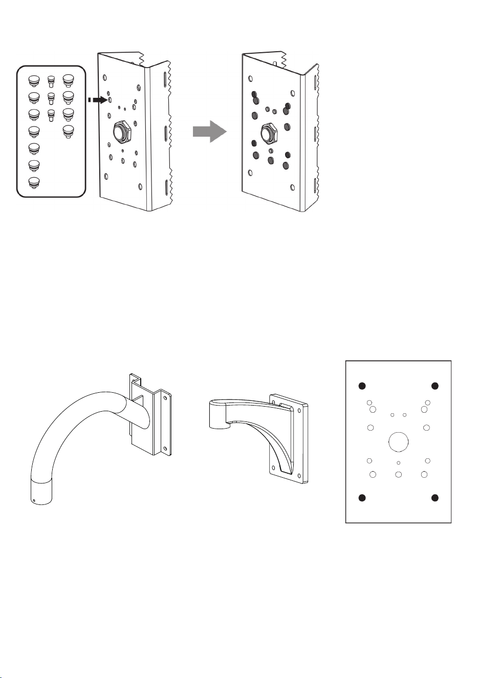
Fill the unused holes on the bracket using the included silicone stoppers. Please check the following drawings for
the mounting holes and the unused holes for your models.
AM-212AM-221
III-3. Goose neck installation: AM-221 and AM-212
Align the mounting holes on the bracket with the mounting holes, and secure it using the included hex bolts,
washers, and nuts.
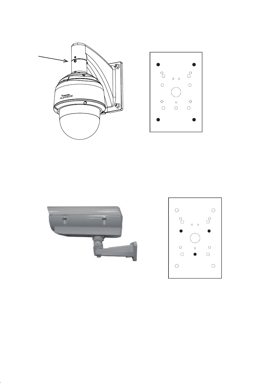
Align the mounting holes on the bracket with the mounting holes (as shown in the drawing), and secure it using
the included hex bolts, washers, and nuts. The enclosure is mounted later after its wall-mount bracket is securely
attached.
AM-519 inside
Speed dome
HD WDR Pro
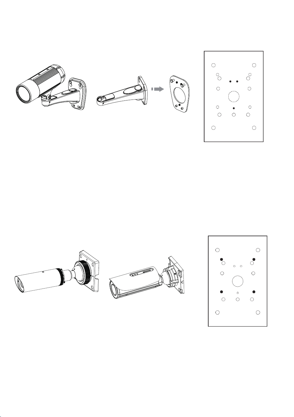
III-4. Speed dome installation: SD83xx Series
Align the mounting holes on the bracket with the mounting holes (as shown in the drawing), and secure it using
the included hex bolts, washers, and nuts.
AE series enclosures
III-5. AE series enclosure installation: AE2000 and others
IP8335/8352/8362
III-6. Camera installation - Medium Bullet: IP8335/8352/8362
Align the mounting holes on the bracket with the mounting holes (as shown in the drawing), and secure it using
the included hex bolts, washers, and nuts.
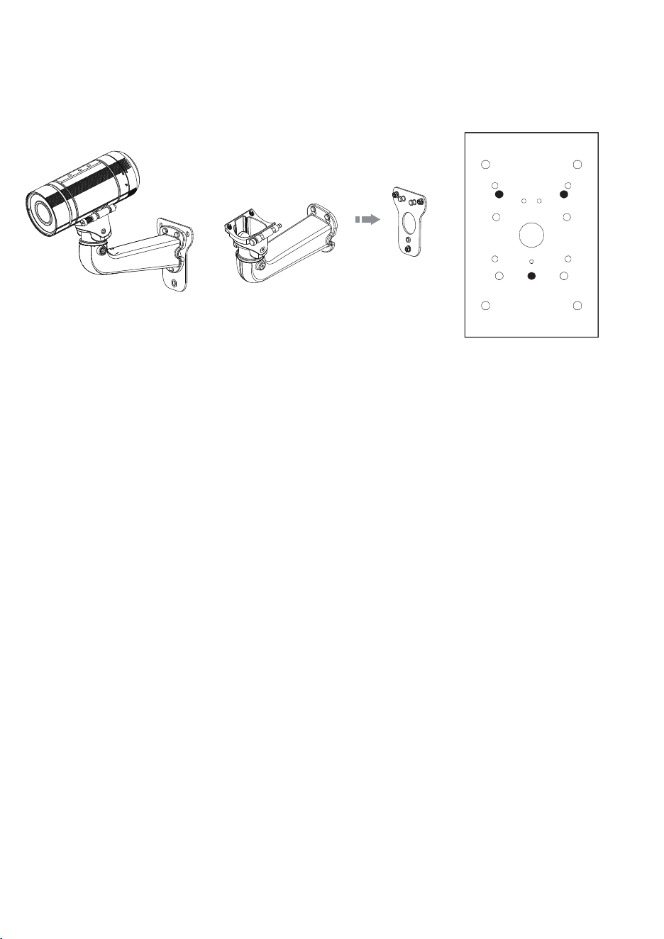
IP8337-H, 8364, 8354-C
IB8367-R, 8338-HR, 8367RT
III-7. Camera installation - Medium Bullet: IP8337-H/8364/8364-C, IB8367-R, 8338-HR, 8367-RT
Align the mounting holes on the bracket with the mounting holes (as hsown in the drawing), and secure it using
the included hex bolts, washers, and nuts.
III-8. Camera installation - Large Bullet: IP8371E, IP8372, IB8373-EH, IB8381(-E), IP8355(E)H,
IP8365(E)H, IP8335H, IP8362
Align the mounting holes on the bracket with the mounting holes (as shown in the drawing), and secure it using
the included hex bolts, washers, and nuts. Refer to the camera's documentation for the rest of the details.
NOTE: There is no need to apply silicone stoppers to the AM-221.
Use M8X25mm screws
Use M6X35mm screws
Use M6X35mm screwsUse M4X15mm screws
Use M6X20mm screws
Use M8X25mm screws
Fill the unused holes on the bracket using the included silicone stoppers. Please check the following drawings for
the mounting holes and the unused holes for your models.
AM-212AM-221
III-3. Goose neck installation: AM-221 and AM-212
Align the mounting holes on the bracket with the mounting holes, and secure it using the included hex bolts,
washers, and nuts.
Align the mounting holes on the bracket with the mounting holes (as shown in the drawing), and secure it using
the included hex bolts, washers, and nuts. The enclosure is mounted later after its wall-mount bracket is securely
attached.
AM-519 inside
Speed dome
HD WDR Pro
III-4. Speed dome installation: SD83xx Series
Align the mounting holes on the bracket with the mounting holes (as shown in the drawing), and secure it using
the included hex bolts, washers, and nuts.
AE series enclosures
III-5. AE series enclosure installation: AE2000 and others
IP8335/8352/8362
III-6. Camera installation - Medium Bullet: IP8335/8352/8362
Align the mounting holes on the bracket with the mounting holes (as shown in the drawing), and secure it using
the included hex bolts, washers, and nuts.
IP8337-H, 8364, 8354-C
IB8367-R, 8338-HR, 8367RT
III-7. Camera installation - Medium Bullet: IP8337-H/8364/8364-C, IB8367-R, 8338-HR, 8367-RT
Align the mounting holes on the bracket with the mounting holes (as hsown in the drawing), and secure it using
the included hex bolts, washers, and nuts.
III-8. Camera installation - Large Bullet: IP8371E, IP8372, IB8373-EH, IB8381(-E), IP8355(E)H,
IP8365(E)H, IP8335H, IP8362
Align the mounting holes on the bracket with the mounting holes (as shown in the drawing), and secure it using
the included hex bolts, washers, and nuts. Refer to the camera's documentation for the rest of the details.
NOTE: There is no need to apply silicone stoppers to the AM-221.
Use M8X25mm screws
Use M6X35mm screws
Use M6X35mm screwsUse M4X15mm screws
Use M6X20mm screws
Use M8X25mm screws