

DIGITAL AUTOMOTIVE ANALYSER/
INSULATION TESTER - HYBRID VEHICLES
MODEL NO: TA320.V2
Thank you for purchasing a Sealey product. Manufactured to a high standard, this product will, if used according to these
instructions, and properly maintained, give you years of trouble free performance.
IMPORTANT: PLEASE READ THESE INSTRUCTIONS CAREFULLY. NOTE THE SAFE OPERATIONAL REQUIREMENTS, WARNINGS & CAUTIONS.
USE THE PRODUCT CORRECTLY AND WITH CARE FOR THE PURPOSE FOR WHICH IT IS INTENDED. FAILURE TO DO SO MAY CAUSE DAMAGE
AND/OR PERSONAL INJURY AND WILL INVALIDATE THE WARRANTY. KEEP THESE INSTRUCTIONS SAFE FOR FUTURE USE.
1. SAFETY
9 Wear safety eye protection that meets ANSI standards.
9 Operate the vehicle to be tested in a well ventilated area. Exhaust gases are poisonous. If necessary connect the vehicle
exhaust to a fume extraction system.
9 Place chocks in front of the drive wheels and never leave the vehicle unattended whilst testing is in progress.
9 Be extra cautious when working in close proximity to the ignition coil, distributor cap, ignition wires and spark plugs. These
components create hazardous voltages when the engine is running.
9 Ensure that the handbrake is on and the gearbox is in neutral or ‘Park’ for automatic transmissions.
9 Keepreextinguishersnearbythataresuitableforpetrol/chemical/electricalres.
9 Keep the analyser clean and in good condition.
9 Remain vigilant when using the code reader on, or near, machinery where there are rotational parts such as belts, pulleys
and fans.
9 Removeillttingclothing.Removeties,watches,rings,andotherloosejewellery,andcontainand/ortiebacklonghair.
9 Maintaincorrectbalanceandfooting.Ensuretheoorisnotslipperyandwearnon-slipshoes.
9 Keep product surfaces clean and dry.
8 DO NOT attempt to connect or disconnect any test equipment whilst the ignition is on or the engine is running.
8 DO NOTusetheanalyserifdamageissuspected.Ifsuspecteddamageoccurswiththedevice,haveitinspectedbyqualied
service personnel before using it again.
8 DO NOT get the analyser wet or use in damp or wet locations or areas where there is condensation.
8 DO NOT use the analyser for any purpose other than for which it is designed.
8 DO NOT allow untrained persons to use analyser.
8 DO NOTusetheanalyserwhenyouaretiredorundertheinuenceofalcohol,drugsorintoxicatingmedication.
8 DO NOToperateinapotentiallyexplosiveenvironment/atmosphere.
WARNING: The warnings, cautions and instructions discussed in this instruction manual cannot cover all possible conditions
and situations that may occur. It must be understood that common sense and caution are factors which cannot be built into
this product, but must be applied by the operator.
2. INTRODUCTION
Specially designed for hybrid vehicles and conforms to EN61010 CAT III (1000V) and CAT IV (600V). Unlike other multimeters this
unit has an insulation test function that allows testing of the insulation of the high voltage cables and motor generator units found on
hybrid vehicles. Can be used as a standalone device or linked wirelessly with a USB interface to a PC or laptop enabling results to be
graphed, saved or printed. Supplied with high voltage probes, thermocouple soft storage bag and wireless USB cable. The unit also has
theusualfunctionsexpectedonahighqualitymultimeterincludingtrueRMS(Root-Mean-Square)andIP67waterproofrating.
Refer to
instructions
TA320.V2Issue113/07/2021
Original Language Version
© Jack Sealey Limited

3. SPECIFICATION
Tach (rpm): ........................................................................ No
Dwell: ................................................................................ No
AC Voltage: ............................. 400mV, 4V, 40V, 400V, 1000V
Voltage: ................................... 400mV, 4V, 40V, 400V, 1000V
AC Current: ................... 400µA, 4000µA, 40mA, 400mA, 10A
DC Current: ................... 400µA, 4000µA, 40mA, 400mA, 10A
Capacitance: . 40nF, 400nF, 4µF, 40µF, 400µF, 4000µF, 40mF
Frequency: ......................................................... 40Hz-10kHz
Duty Cycle: ............................................................0.1-99.9%
Pulse Width: ..................................................... 100µs-100ms
Resistance: ............... 400Ω,4kΩ,40kΩ,400kΩ,4MΩ,40MΩ
Continuity: .................................................................. <35Ω
Temperature: ........................ -50to+1000°C,-58to+1832°F
IR Temperature: ................................................................ No
Insulation Test: ............................... 125V, 250V, 500V, 1000V
Diode Check: ................................................................... Yes
Transistor Test: ................................................................. No
Back Light: ....................................................................... Yes
Bar-GraphDisplay: .......................................................... Yes
Display Hold: .................................................................... Yes
Auto-Ranging: .................................................................. Yes
Inductive Coupler: ............................................................. No
PC Interface: .................................................................... Yes
Digits Height: ............................................................... 20mm
AutoPowerO: ................................................................ Yes
Low Battery Indicator: ...................................................... Yes
Batteries (supplied): .............................................6 x 1.5V AA
Hi-ImpactCase: ............................................................... Yes
Size (L x W x D): .........................................220x95x56mm
PC Compatibility: ..................Windows2000,XP,Vista,Win7
TA320.V2Issue113/07/2021
Original Language Version
© Jack Sealey Limited
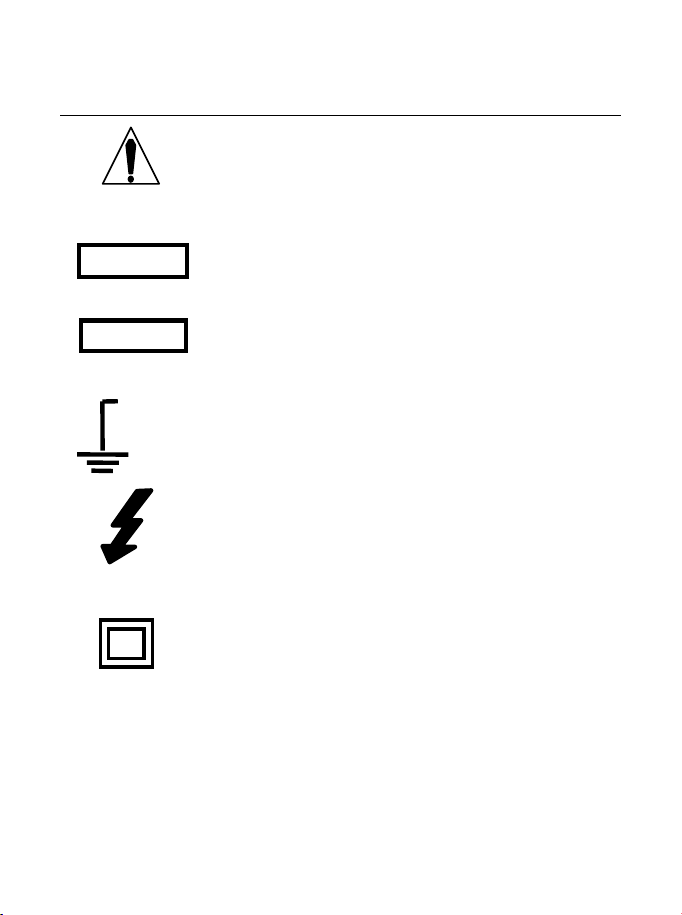
Safety Symbols
This symbol adjacent to another symbol, terminal
or operating device indicates that the operator
must refer to an explanation in the Operating
Instructions to avoid personal injury or damage to
the meter.
This WARNING symbol indicates a potentially
hazardous situation, which if not avoided, could
result in death or serious injury.
This CAUTION symbol indicates a potentially
hazardous situation, which if not avoided, may
result in damage to the product.
This symbol advises the user that the terminal(s)
so marked must not be connected to a circuit point
at which the voltage with respect to earth ground
exceeds (in this case) 1000 VAC or VDC.
This symbol adjacent to one or more terminals
identifies them as being associated with ranges
that may, in normal use, be subjected to
particularly hazardous voltages. For maximum
safety, the meter and its test leads should not be
handled when these terminals are energized.
This symbol indicates that a device is protected
throughout by double insulation or reinforced
insulation.
WARNING
CAUTION
MAX
1000V

PER IEC1010 OVERVOLTAGE INSTALLATION CATEGORY
OVERVOLTAGE CATEGORY I
Equipment of OVERVOLTAGE CATEGORY I is equipment for
connection to circuits in which measures are taken to limit the
transient overvoltages to an appropriate low level.
Note – Examples include protected electronic circuits.
OVERVOLTAGE CATEGORY II
Equipment of OVERVOLTAGE CATEGORY II is energy-consuming
equipment to be supplied from the fixed installation.
Note – Examples include household, office, and laboratory appliances.
OVERVOLTAGE CATEGORY III
Equipment of OVERVOLTAGE CATEGORY III is equipment in fixed
installations.
Note – Examples include switches in the fixed installation and some
equipment for industrial use with permanent connection to the fixed
installation.
OVERVOLTAGE CATEGORY IV
Equipment of OVERVOLTAGE CATEGORY IV is for use at the
origin of the installation.
Note – Examples include electricity meters and primary
over-current protection equipment

ELECTRICAL SAFETY PRECAUTIONS
This meter has been designed for safe use, but must be operated with
caution. The rules listed below must be carefully followed for safe
operation.
1. NEVER apply voltage or current to the meter that exceeds the
specified maximum:
Input Protection Limits
Function Maximum Input
V DC or V AC 1000VDC/AC rms
mA AC/DC 500mA 1000V fast acting fuse
A AC/DC
10A 1000V fast acting fuse (20A
for 30 seconds max every 15
minutes)
Frequency, Resistance,
Capacitance, Duty Cycle,
Diode Test, Continuity
1000VDC/AC rms
Temperature 1000VDC/AC rms
Surge Protection: 8kV peak per IEC 61010
2. USE EXTREME CAUTION when working with high voltages.
3. DO NOT measure voltage if the voltage on the "COM" input jack
exceeds 1000V above earth ground.
4. NEVER connect the meter leads across a voltage source while
the function switch is in the current, resistance, or diode mode.
Doing so can damage the meter.
5. ALWAYS discharge filter capacitors in power supplies and
disconnect the power when making resistance or diode tests.
6. ALWAYS turn off the power and disconnect the test leads before
opening the covers to replace the fuse or batteries.
7. NEVER operate the meter unless the back cover and the battery
and fuse covers are in place and fastened securely.
If the equipment is used in a manner not specified by the
manufacturer, the protection provided by the equipment may be
impaired.
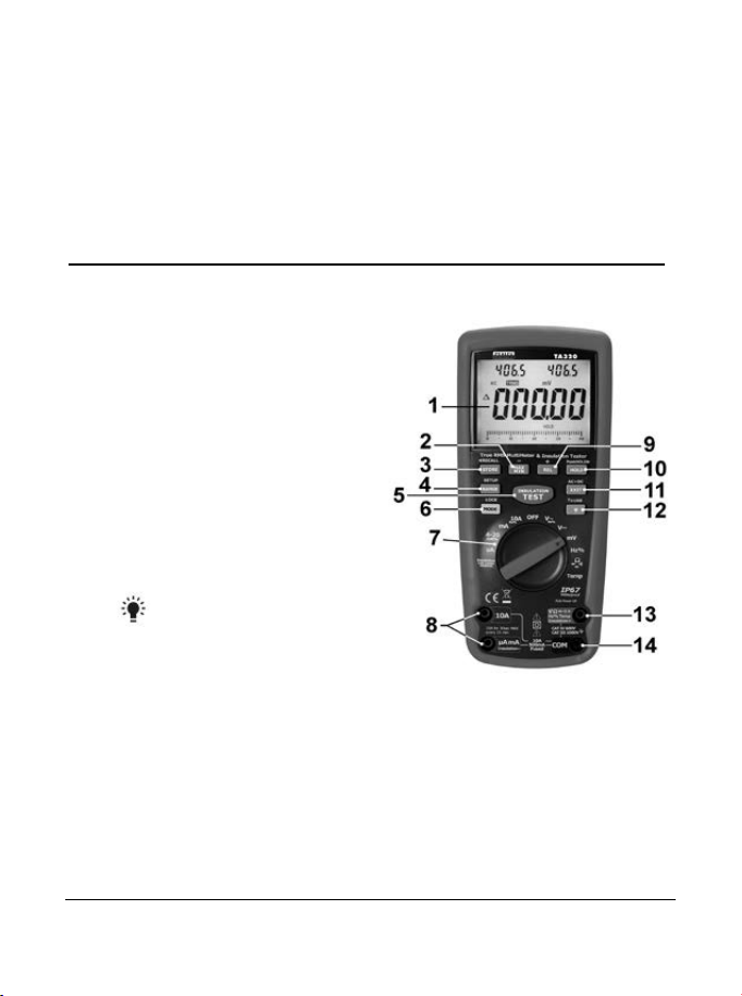
Controls and Jacks
1. 40,000 count LCD display
2. MAX/MIN (-)button
3. STORE(<RECALL) button
4. RANGE(SETUP) button
5. INSULATION TEST button
6. MODE button
7. Function switch
8. mA, µA and 10A input jacks
9. REL(+) button
10. HOLD(PEAKHOLD>) button
11. EXIT(AC+DC) button
12. Backlight and RF button
13. Positive input jack
14. COM input jack
Note: Tilt stand and battery compartment are on rear of unit.
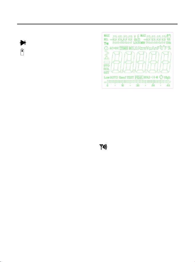
Symbols and Annunciators
•))) Continuity
Diode test
Battery status
n nano (10
-9
) (capacitance)
µ micro (10
-6
) (amps, cap)
m milli (10
-3
) (volts, amps)
A Amps
k kilo (10
3
) (ohms)
F Farads (capacitance)
M mega (10
6
) (ohms)
Ω Ohms PEAK Peak Hold
Hz Hertz (frequency) V Volts
% Percent (duty ratio) REL Relative
AC Alternating current AUTO Autoranging
DC Direct current HOLD Display hold
ºF Degrees Fahrenheit ºC Degrees Centigrade
MAX Maximum MIN Minimum
No. Serial number RF transmitter active
S Second
left auxiliary display
right auxiliary display
SET Set up parameter
AC+DC Alternating current + Direct current
TRMS True RMS
STO Store
RCL Recall
AUTO Auto Range
Timing symbol
Backlight
Bar graph
Operating Instructions
WARNING: Risk of electrocution. High-voltage circuits, both AC and
DC, are very dangerous and should be measured with great care.
1. ALWAYS turn the function switch to the OFF position when the
meter is not in use.
2. If “OL” appears in the display during a measurement, the value
exceeds the range you have selected. Change to a higher range.
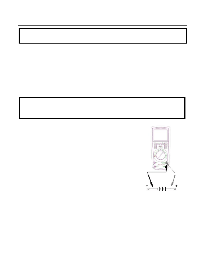
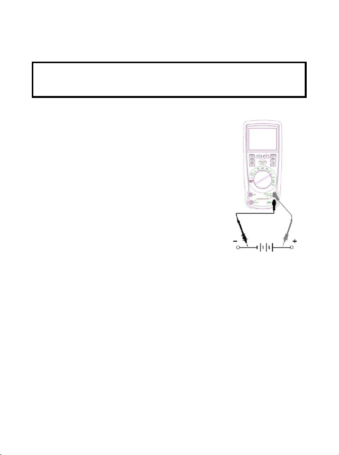
DC VOLTAGE MEASUREMENTS
CAUTION: Do not measure DC voltages if a motor on the circuit
is being switched ON or OFF. Large voltage surges may occur
that can damage the meter.
1. Set the function switch to the green VDC
position.
2. Insert the black test lead banana plug into the
negative COM jack.
Insert the red test lead banana plug into the
positive V jack.
3. Touch the black test probe tip to the negative
side of the circuit.
Touch the red test probe tip to the positive
side of the circuit.
4. Read the voltage in the display.
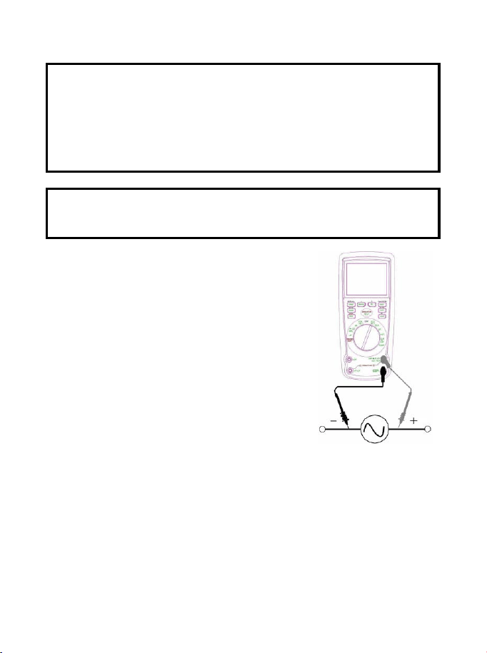
AC VOLTAGE (FREQUENCY, DUTY CYCLE) MEASUREMENTS
WARNING: Risk of Electrocution. The probe tips may not be long
enough to contact the live parts inside some 240V outlets for
appliances because the contacts are recessed deep in the outlets.
As a result, the reading may show 0 volts when the outlet actually
has voltage on it. Make sure the probe tips are touching the metal
contacts inside the outlet before assuming that no voltage is
present.
CAUTION: Do not measure AC voltages if a motor on the circuit
is being switched ON or OFF. Large voltage surges may occur
that can damage the meter.
1. Set the function switch to the green
VAC/Hz/% position.
2. Insert the black test lead banana plug
into the negative COM jack.
Insert red test lead banana plug into the
positive V jack.
3. Touch the black test probe tip to the
neutral side of the circuit.
Touch the red test probe tip to the “hot”
side of the circuit.
4. Read the voltage in the main display and
the frequency in the right auxiliary
display
5. Press and hold the MODE button 2 second to indicate “Hz”.
6. Read the frequency in the main display.
7. Press the MODE button to indicate “%”.
8. Read the % of duty cycle in the main display.
9. Press EXIT for 2 seconds into the function of AC+DC. Test DC
and AC True Rms.
MV VOLTAGE MEASUREMENTS
CAUTION: Do not measure mV voltages if a motor on the circuit
is being switched ON or OFF. Large voltage surges may occur
that can damage the meter.
1. Set the function switch to the green mV position.
2. Press the MODE button to indicate “DC”.or
““AC ”, or in AC range press EXIT for two
seconds and chose ”AC+DC”
Insert the black test lead banana plug into
the negative COM jack.
Insert the red test lead banana plug into
the positive V jack.
3. Touch the black test probe tip to the
negative side of the circuit.
Touch the red test probe tip to the positive
side of the circuit.
4. Read the mV voltage in the display.
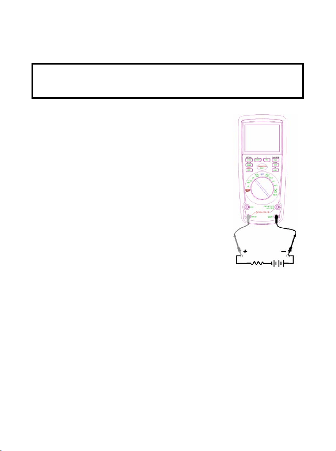
DC CURRENT MEASUREMENTS
CAUTION: Do not make 20A current measurements for longer
than 30 seconds. Exceeding 30 seconds may cause damage to
the meter and/or the test leads.
1. Insert the black test lead banana plug into the negative COM jack.
2. For current measurements up to 4000µA
DC, set the function switch to the yellow µA
position and insert the red test lead banana
plug into the µA/mA jack.
3. For current measurements up to 400mA DC,
set the function switch to the yellow mA
position and insert the red test lead banana
plug into the µA/mA jack.
4. For current measurements up to 20A DC,
set the function switch to the yellow 10A/HZ/%
position and insert the red test lead banana
plug into the 10A jack.
5. Press the MODE button to indicate “DC” on
the display.
6. Remove power from the circuit under test,
then open up the circuit at the point where
you wish to measure current.
7. Touch the black test probe tip to the negative side of the circuit.
Touch the red test probe tip to the positive side of the circuit.
8. Apply power to the circuit.
9. Read the current in the display.
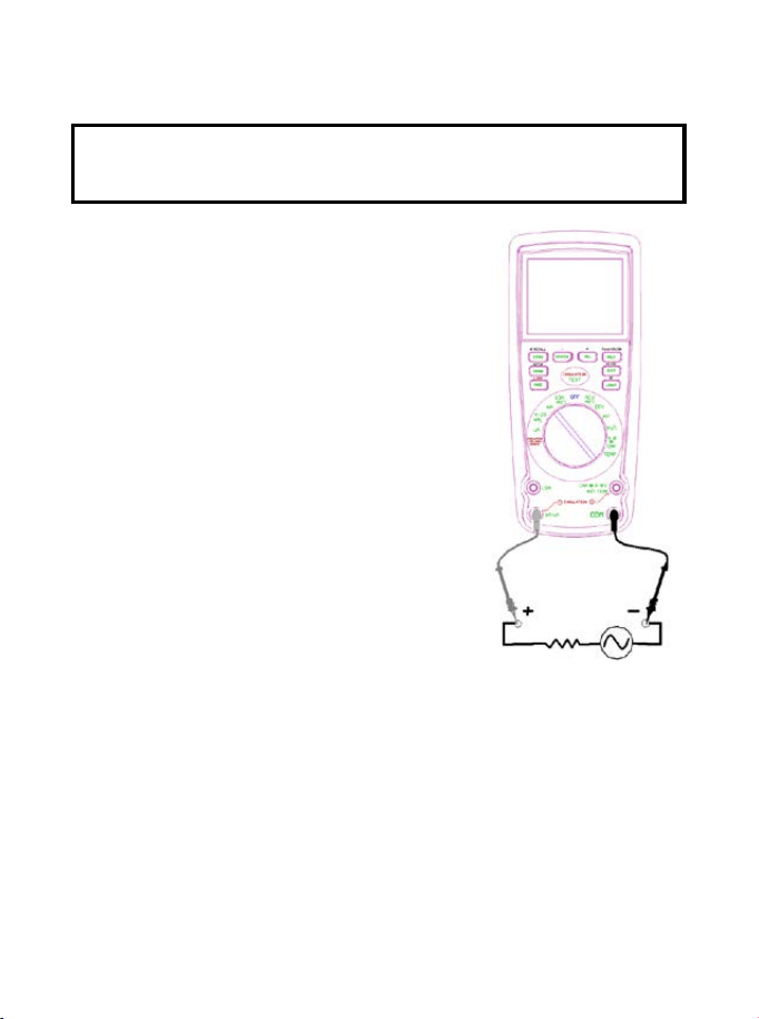
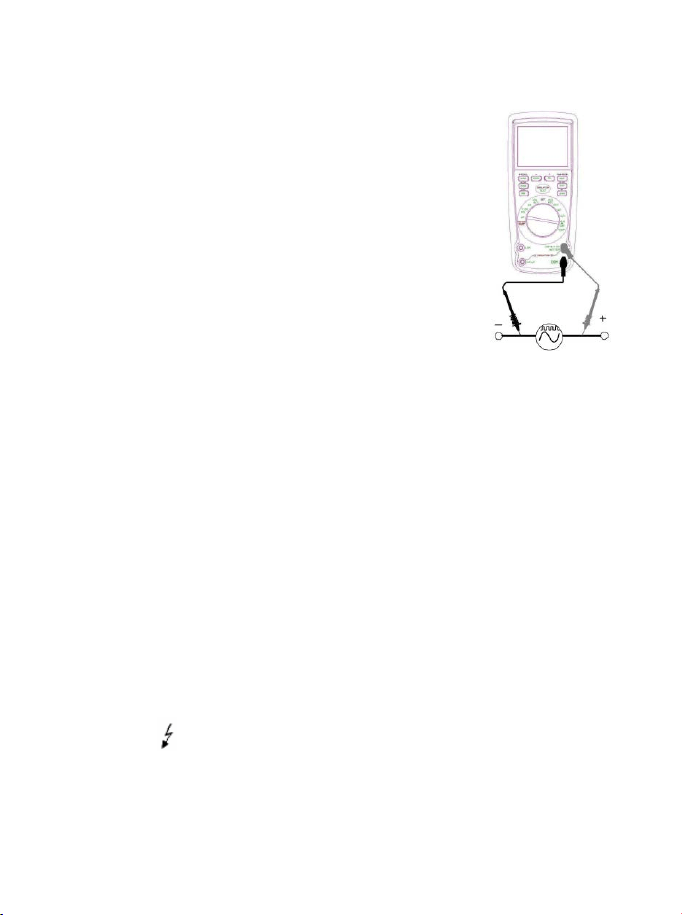
AC CURRENT (FREQUENCY, DUTY CYCLE) MEASUREMENTS
CAUTION: Do not make 20A current measurements for longer
than 30 seconds. Exceeding 30 seconds may cause damage to
the meter and/or the test leads.
1. Insert the black test lead banana plug
into the negative COM jack.
2. For current measurements up to
4000µA AC, set the function switch to
the yellow µA position and insert the
red test lead banana plug into the
µA/mA jack.
3. For current measurements up to
400mA AC, set the function switch to
the yellow mA position and insert the
red test lead banana plug into the
µA/mA jack.
4. For current measurements up to 20A
AC, set the function switch to the
yellow 10A/HZ/% position and insert
the red test lead banana plug into the
10A jack.
5. Press the MODE button to indicate “AC”
on the display.
6. Remove power from the circuit under test, then open up the
circuit at the point where you wish to measure current.
7. Touch the black test probe tip to the neutral side of the circuit.
Touch the red test probe tip to the “hot” side of the circuit.
8. Apply power to the circuit.
9. Read the current in the display. In the 10AAC range, right
auxiliary display frequency.
10. Press and hold the MODE button to indicate “Hz”.
11. Read the frequency in the display.
12. Momentarily press the MODE button again to indicate “%”.
13. Read the % duty cycle in the display.
14. Press and hold the MODE button to return to current
measurement.
15. Press EXIT for 2 seconds into the function of AC+DC. Test DC
and AC True Rms.
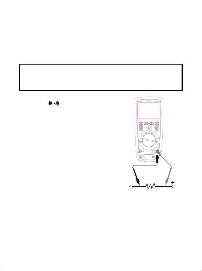
RESISTANCE MEASUREMENTS
WARNING: To avoid electric shock, disconnect power to the unit
under test and discharge all capacitors before taking any
resistance measurements. Remove the batteries and unplug the
line cords.
1. Set the function switch to the green
Ω CAP position.
2. Insert the black test lead banana plug
into the negative COM jack.
Insert the red test lead banana plug into
the positive
Ω jack.
3. Press the MODE button to indicate
“
Ω” on the display.
4. Touch the test probe tips across the
circuit or part under test. It is best to
disconnect one side of the part under
test so the rest of the circuit will not
interfere with the resistance reading.
5. Read the resistance in the display.
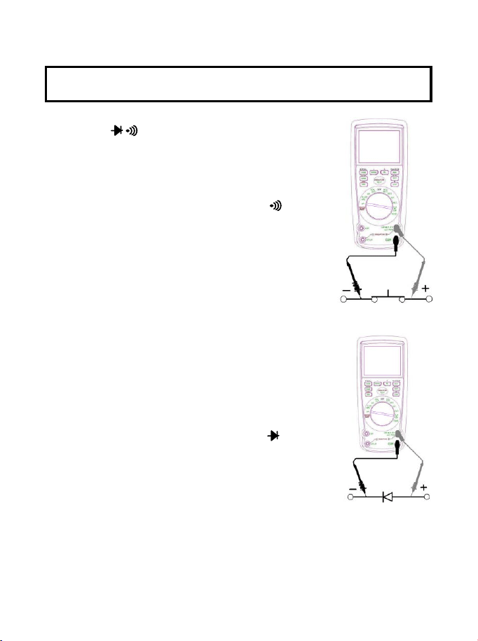
CONTINUITY CHECK
WARNING: To avoid electric shock, never measure continuity on
circuits or wires that have voltage on them.
1. Set the function switch to the green
Ω CAP position.
2. Insert the black lead banana plug into the
negative COM jack.
Insert the red test lead banana plug into the
positive
Ω jack.
3. Press the MODE button to indicate“ "and
“Ω” on the display
4. Touch the test probe tips to the circuit or wire
you wish to check.
5. If the resistance is less than approximately
35Ω, the audible signal will sound. If the
circuit is open, the display will indicate “OL”.
DIODE TEST
1. Set the function switch to the green Ω CAP
position.
2. Insert the black test lead banana plug into the
negative COM jack and the red test lead
banana plug into the positive V jack.
3. Press the MODE button to indicate“ “ and
“V” on the display.
4. Touch the test probes to the diode under test.
Forward voltage will typically indicate 0.400 to
0.700V. Reverse voltage will indicate “OL”.
Shorted devices will indicate near 0V and an
open device will indicate “OL” in both
polarities.
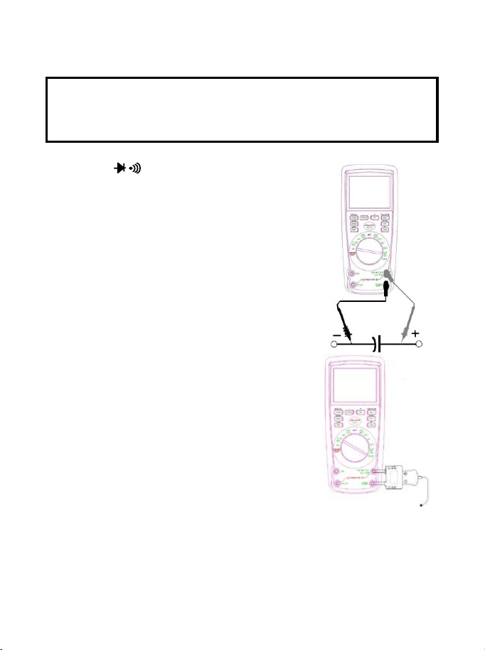
CAPACITANCE MEASUREMENTS
WARNING: To avoid electric shock, disconnect power to the unit
under test and discharge all capacitors before taking any
capacitance measurements. Remove the batteries and unplug the
line cords.
1. Set the rotary function switch to the green
Ω CAP position.
2. Insert the black test lead banana plug into
the negative COM jack.
3. Insert the red test lead banana plug into
the positive V jack.
4. Press the MODE button to indicate “F”
5. Touch the test leads to the capacitor to be
tested.
Read the capacitance value in the
Display
TEMPERATURE MEASUREMENTS
1. Set the function switch to the green
Temp position.
2. Insert the Temperature Probe into the
input jacks, making sure to observe the
correct polarity.
3. Press the MODE button to indicate “ºF”
or “ºC”
4. Touch the Temperature Probe head to
the part whose temperature you wish to
measure. Keep the probe touching the
part under test until the reading
stabilizes (about 30 seconds).
5. Read the temperature in the display.
Note: The temperature probe is fitted with a type K mini connector.
A mini connector to banana connector adaptor is supplied for
connection to the input banana jacks.
FREQUENCY (DUTY CYCLE) MEASUREMENTS (ELECTRONIC)
1. Set the rotary function switch to the green Hz/% position.
2. Insert the black lead banana plug into the
negative COM jack and the red test lead
banana plug into the positive Hz jack.
3. Touch the test probe tips to the circuit under
test.
4. Read the frequency on the display.
5. Press the MODE button to indicate “%”.
6. Read the % duty cycle in the display.
% 4 – 20mA MEASUREMENTS
1. Set up and connect as described for DC mA measurements.
2. Set the rotary function switch to the 4-20mA% position.
3. The meter will display loop current as a % with 0mA=-25%,
4mA=0%, 20mA=100%, and 24mA=125%.
INSULATION RESISTANCE MEASUREMENTS
a)Set the rotary function switch to the INSULATION position
and Press the RANGE button to chose one of the voltages
displayed in the top left corner.
b)Connect two testing lines to the item to be tested.
c)Push down and hold the “TEST” button or press the “LOCK” key first
and then the “TEST” button, if there is any static electricity present
in the item being tested and its voltage is over 30V, it will fail and no
high-voltage testing will occur, “>30V” will display on the LCD, the
symbol “ ” flashes, and the buzzer will sound. Otherwise it will
enter into the formal testing process and the high-voltage will show
on the primary display, the insulation resistance in MΩ is indicated
in-phase with the analog bar; on the top right corner display, the

tested insulation voltage in V (DC) is indicated, the symbol “ ”
flashes and the buzzer will sound.
d)Releasing the “TEST” button or pushing down the “TEST” button in
the “LOCK “ status will exit from the “LOCK” status and shut-off the
testing voltage, simultaneously the resistance value indicated in the
primary display will be held, and the top right corner display will still
show the status of the insulation voltage for the item tested.
Turning the function switch to off or pressing the EXIT button
will exit from the testing procedure during the process.
POWER TOOLS AND SMALL APPLIANCES
This test would also apply to other similar equipment that has a line
cord. For double insulated power tools, the megohmmeter lead shown
connected to the housing would be connected to some metal part lf
the tool(e.g. chuck, blade).
Note: The switch of the device must be in the “ON” position and the
main power should be disconnected.
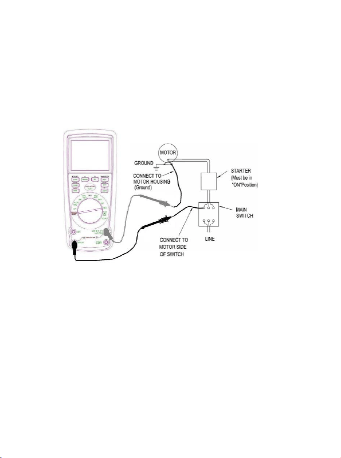
MOTORS
AC-Disconnect the motor from the line by disconnecting the wires at
the motor terminals or by opening the main switch. If the main switch
is used and the motor also has a starter then the starter must be held,
by some means, in the “ON” position. In the latter case, the measured
resistance will include the resistance of the motor, wire and all other
components between the motor and the main switch. If a weakness is
indicated, the motor and other components should be checked
individually. If the motor is disconnected at the motor terminals,
connect one megohmmeter lead to the grounded motor housing and
the other lead to one of the motor leads. DC - Disconnect the motor
from the line. To test the brush rigging, field coils and armature
connect one megohmmeter lead to the grounded motor housing and
the other lead to the brush on the commutator. If the resistance
measurement indicates a weakness, raise the brushes off the
commutator and separately test the armature, field coils and brush
rigging by connecting one megohmmeter lead to each of them
individually, leaving the other connected to the grounded motor
housing. The above also applies to DC Generators.
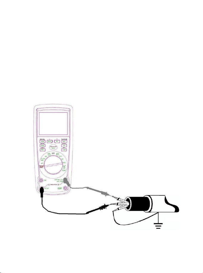
CABLES
Disconnect the cable from the line. Also disconnect opposite end to
avoid errors due to leakage from other equipment. Check each
conductor to ground and /or lead sheath by connecting one
megohmmeter lead to a ground and /or lead sheather and the other
megohmmeter lead to each of the conductors in turn. Check insulation
resistance between conductors by connecting megohmmeter leads to
conductors in pairs.

AUTORANGING/MANUAL RANGE SELECTION
When the meter is first turned on, it automatically goes into
AutoRanging. This automatically selects the best range for the
measurements being made and is generally the best mode for most
measurements. For measurement situations requiring that a range
be manually selected, perform the following:
1. Press the RANGE key. The “AUTO” display indicator will turn off.
2. Press the RANGE key to step through the available ranges until
you select the range you want.
3. To exit the Manual Ranging mode and return to Autoranging,
press EXIT
Note: Manual ranging does not apply for the Temperature functions.
MAX/MIN
1. Press the MAX/MIN key to activate the MAX/MIN recording mode.
The display icon "MAX" will appear. The meter left auxiliary
display will display and hold the maximum reading and will update
only when a new “max” occurs. The display icon "MIN" will appear.
The right auxiliary display meter will display and hold the
minimum reading and will update only when a new “min” occurs.
2.To exit MAX/MIN mode press EXIT
RELATIVE MODE
The relative measurement feature allows you to make
measurements relative to a stored reference value. A reference
voltage, current, etc. can be stored and measurements made in
comparison to that value. The displayed value is the difference
between the reference value and the measured value. Note:
Relative mode does not operate in the 4-20mA function.
1. Perform the measurement as described in the operating
instructions.
2. Press the REL button to store the reading in the display and the
"REL" indicator will appear on the display.

3. Left auxiliary display shows the margin of initial value and the
current value.
Right auxiliary display shows the initial reading. Main displays
the reading after REL TEST.
4. Press the EXIT button to exit the relative mode.
Display Backlight
Press the key to turn the backlight on. The backlight will
automatically turn off after SET time. Press the EXIT button to
exit the backlight on mode.
HOLD
The hold function freezes the reading in the display. Press the
HOLD
key momentarily to activate or to exit the
HOLD
function.
PEAK HOLD
The Peak Hold function captures the peak AC or DC voltage or
current. The meter can capture negative or positive peaks as fast
as 1 millisecond in duration. Momentarily press the PEAK button,
“PEAK” and “MAX” will display in left auxiliary display. MIN” will
display in right auxiliary display. The meter will update the display
each time a lower negative peak occurs. Press the EXIT button to
exit the PEAK HOLD mode. Auto Power Off feature will be
disabled automatically in this mode.
DATA STORAGE
1. Set the function switch to the measurement function desired.
2. Press the STORE button to access the recording interval time
set up function.
3. The auxiliary display on the left indicates 0000 S, which is the
recording sample rate; use the + & - buttons to select the
desired sample rate (0 to 255 seconds)
4. Set the sample rate to 0000 S for manual recording. In this
mode, each press of the STORE button will save one
measurement reading.

5. Set the sample rate (from 1 to 255 S) for automatic recording.
In this mode, pressing the STORE button will start data
recording at the programmed sample rate.
6. The auxiliary display on the left indicates the current storage
location (0000 to 9999). New measurements will begin storing
into the next available location.
7. Press and hold the STORE button for 2 seconds to enter the
RECALL mode or press EXIT to return to the normal operating
mode.
DATA STORAGE RECALL
1. Press and hold the STORE button for two seconds (if not
already done as instructed in step 7 in the above procedure) to
enter the RECALL function.
2. The auxiliary display on the left will show XXXX (current
storage location). The auxiliary display on the right will show
XXXX (number of storage locations used).
3. Use the + and - buttons to navigate the storage locations. The
value for the selected location is indicated in the main display.
4. Press the EXIT button to end the recall session.
CLEAR ALL DATA
1. From the OFF position, press and hold the RANGE button
while turning the function switch to any on position
2. Release the RANGE button. The memory has been cleared

PC WIRELESS COMMUNICATION
1. Install and launch the PC software (refer to the HELP utility
contained in the software for more details)
2. Press and Hold the backlight/USB button for two seconds to
enter RF wireless transmit mode
3. The RF icon will appear on the display
4. When communication is established, the RF icon on the
display will blink and the LED indicator on the receiver will
blink
5. Once per second, the data will be displayed on the PC screen
(plotted on the graph and inserted to the data list)
6. Hold the backlight button for two seconds to exit the RF
wireless transmit mode
SENDING STORED DATA TO THE PC
1. Launch the PC software
2. Press the STORE button for two seconds to enter into data
RECALL function.
3. Press the HOLD button for two seconds. The RF transmit icon
will flash while the stored data is sent to the PC
NOTE: Refer to the HELP utility included in the supplied
software program for in-depth software instructions.
SETUP
1. Press and Hold the RANGE/SETUP button for two seconds to
enter the SET function. The first of five settable functions will
appear.
2. Press the RANGE button to step through the functions
a: Alarm High limit buzzer alarm OFF or Value
b: Alarm Low limit buzzer alarm OFF or Value
c: Auto power off time OFF, 10 to 30 sec
d: Button beeper ON/OFF
e: Back light time OFF, 10 to 30 sec
3. Use the +, - ,◄ and ► buttons to select and change conditions
and digits.

4. Press the RANGE/SETUP button until the meter returns to the
normal display to exit this mode.
ALARM LIMITS
1. Press and Hold the SETUP button for two seconds to enter the
High Limit function.
2. Press the ► button to select a digit for adjustment
3. Press the + or – button to adjust the value of the digit
4. Press the
◄ button to turn the alarm OFF.
5. Press the SETUP button and repeat the procedure to set the
low limit
6. Press the SETUP button to step through the other functions
and return to the normal operating mode.
7. The meter will “beep” if the measured value is greater than the
high limit or lower than the low limit.
.
AC+DC
In all the measuring mode VAC,mV(AC),10A(AC),mA(AC),uA(AC),
press button EXIT for 2 seconds to enter into AC+DC testing. The
precision is the same as AC measure. LCD shows AC+DC signal.
Press button EXIT to exit.
LOW BATTERY INDICATION
When the icon appears alone in the display, the batteries
should be replaced.

Maintenance
WARNING: To avoid electric shock, disconnect the test leads from
any source of voltage before removing the back cover or the battery
or fuse covers.
WARNING: To avoid electric shock, do not operate your meter until
the battery and fuse covers are in place and fastened securely.
This Meter is designed to provide years of dependable service, if the
following care instructions are performed:
1. KEEP THE METER DRY. If it gets wet, wipe it dry immediately.
2. USE AND STORE THE METER IN NORMAL TEMPERATURES.
Temperature extremes can shorten the life of the electronic parts
and distort or melt plastic parts.
3. HANDLE THE METER GENTLY AND CAREFULLY. Dropping it
can damage the electronic parts or the case.
4. KEEP THE METER CLEAN. Wipe the case occasionally with a
damp cloth. DO NOT use chemicals, cleaning solvents, or
detergents.
5. USE ONLY NEW BATTERIES OF THE RECOMMENDED SIZE
AND TYPE. Remove old batteries so they do not leak and
damage the unit.
6. IF THE METER IS TO BE STORED FOR A LONG PERIOD OF
TIME, the batteries should be removed to prevent damage to the
unit.
BATTERY INSTALLATION
WARNING: To avoid electric shock, disconnect the test leads from
any source of voltage before removing the battery cover.
1. Turn power off and disconnect the test leads from the meter.
2. Open the rear battery cover by removing 4 screws using a cross
head screwdriver.

3. Insert the batteries into battery holder, observing the correct
polarity.
4. Put the battery cover back in place. Secure with the screws.
WARNING: To avoid electric shock, do not operate the meter until
the battery cover is in place and fastened securely.
NOTE: If your meter does not work properly, check the fuses and
batteries to make sure that they are still good and that they are
properly inserted.

REPLACING THE FUSES
WARNING: To avoid electric shock, disconnect the test leads from
any source of voltage before removing the meter cover.
1. Disconnect the test leads from the meter.
2. Remove the protective rubber holster.
3. Remove the battery cover (4 screws) and the batteries.
4. Remove the six screws securing the rear cover.
5. Gently remove the old fuse and install the new fuse into the
holder.
6. Always use a fuse of the proper size and value (0.5A/1000V fast
blow for the 400mA range, 10A/1000V fast blow for the 20A range.
7. Replace and secure the rear cover, battery and battery cover.
WARNING: To avoid electric shock, do not operate your meter until
the fuse cover is in place and fastened securely.
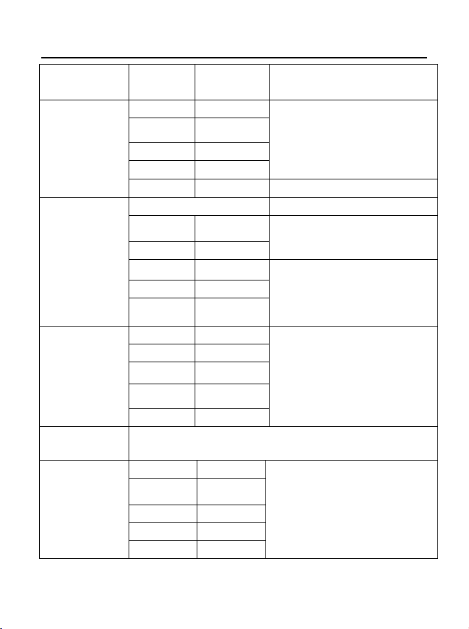
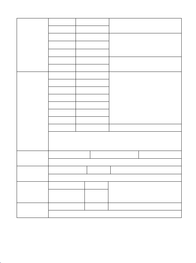
Specifications
Function
Range
Resolution
Accuracy
DC Voltage
400mV
0.01mV
± (0.06% reading + 4digits)
4V
0.0001V
40V
0.001V
400V
0.01V
1000V
0.1V
± (0.1% reading + 5digits)
AC Voltage
50 to 1000Hz
400mV
0.1mV
± (1.0% reading + 7digits)
4V
0.001V
40V
0.01V
± (1.0% reading + 5 digits)
400V
0.1V
1000V
1V
AC+DCVoltage
400mV
0.1mV
± (1.0% reading + 7digits)
(50/60HZ)
4V
0.001V
40V
0.01V
400V
0.1V
1000V
1V
All AC voltage ranges are specified from 5% of range to
100% of range
DC Current
400µA 0.01µA
± (1.0% reading + 3 digits)
4000µA 0.1µA
40mA
0.001mA
400mA
0.01mA
10A
0.001A
(20A: 30 sec max with reduced accuracy)
AC Current
400
µ
A
0.1
µ
A
± (1.5% reading + 7digits)
(50 to 1000Hz)
4000
µ
A
1
µ
A
40mA
0.01mA
400mA 0.1mA
10A 0.01A
AC+DCCurrent
400µA
0.1µA
± (1.5% reading + 7digits)
(50/60HZ)
4000µA 1µA
40mA
0.01mA
400mA
0.1mA
10A
0.01A
(20A: 30 sec max with reduced accuracy)
All AC current ranges are specified from 5% of range to
100% of range
NOTE: Accuracy is stated at 65
o
F to 83
o
F (18
o
C to 28
o
C) and less
than 75% RH.
AC switch according to the calibration of sine wave. It generally
increase ±(2% reading + 2% full scale) if non sine wave in the
wave crest less than 3.0.
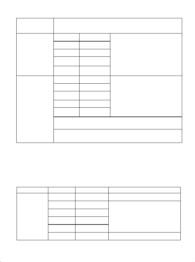
Function
Range
Resolution
Accuracy
Resistance
400
Ω
0.01
Ω
±
(0.3% reading + 9 digits)
4kΩ
0.0001kΩ
± (0.3% reading + 4 digits)
40kΩ 0.001kΩ
400k
Ω
0.01k
Ω
4M
Ω
0.001M
Ω
40MΩ 0.001MΩ ± (2.0% reading + 10 digits)
Capacitance
40nF
0.001nF
± (3.5% reading + 40 digits)
400nF
0.01nF
4µF
0.0001µF
± (3.5% reading + 10 digits)
40
µ
F
0.001
µ
F
400
µ
F
0.01
µ
F
4000µF
0.1µF
± (5% reading + 10 digits)
40mF
0.001mF
Frequency
(electronic)
40Hz
0.001Hz
± (0.1% reading + 1 digits)
400Hz
0.01Hz
4kHz 0.0001kHz
40kHz
0.001kHz
400kHz
0.01kHz
4MHz 0.0001MHz
40MHz
0.001MHz
100MHz
0.01MHz
Not specified
Sensitivity: 0.8V rms min. @ 20% to 80% duty cycle and
<100kHz; 5Vrms min @ 20% to 80% duty cycle and >
100kHz.
Frequency
(electrical)
40.00Hz-10KHz
0.01Hz - 0.001KHz
±
(0.5% reading)
Sensitivity:2Vrms
Duty Cycle
0.1 to 99.90%
0.01%
±
(1.2% reading + 2 digits)
Pulse width: 100µs - 100ms, Frequency: 5Hz to 150kHz
Temp
(type-K)
-50 to 1200
°
C
0.1
°
C
±(1.0% reading + 2.5°C)
±(1.0% reading +4.5°F)
(probe accuracy not included)
-58 to 2192°F 0.1°F
4-20mA%
-25 to 125%
0.01%
±50 digits
0mA=-25%, 4mA=0%, 20mA=100%, 24mA=125%

Meg OHMS
Terminal
Voltage
Range Resolution Accuracy Test
Current
Short
circuit
current
125V(0
%~+10
%)
0.125~4.000 MΩ
0.001MΩ
+(2%+10)
1mA
@load1
25kΩ
≤
1mA
4.001~40.00 MΩ
0.01MΩ
+(2%+10)
40.01~400.0 MΩ
0.1MΩ
+(4%+5)
400.1~4000 MΩ
1MΩ
+(5%+5)
250V
(0%~+1
0%)
0.250~4.000 MΩ
0.001MΩ
+(2%+10)
1mA
@load2
50kΩ
≤
1mA
4.001~40.00 MΩ
0.01MΩ
+(2%+10)
40.01~400.0 MΩ
0.1MΩ
+(3%+5)
400.1~4000 MΩ
1MΩ
+(4%+5)
500V(0
%~+10
%)
0.500~4.000 MΩ
0.001MΩ
+(2%+10)
1mA
@load5
00kΩ
≤
1mA
4.001~40.00 MΩ
0.01MΩ
+(2%+10)
40.01~400.0 MΩ
0.1MΩ
+(2%+5)
400.1~4000 MΩ
1MΩ
+(4%+5)
1000V
(0%~+1
0%)
1.000~4.000 MΩ
0.001MΩ
+(3%+10)
1mA
@load1
MΩ
≤
1mA
4.001~40.00 MΩ
0.01MΩ
+(2%+10)
40.01~400.0 MΩ
0.1MΩ
+(2%+5)
400.1~4000 MΩ
1MΩ
+(4%+5)
Note: Accuracy specifications consist of two elements:
• (% reading) – This is the accuracy of the measurement circuit.
• (+ digits) – This is the accuracy of the analog to digital converter.

Store capacitance 2000
Enclosure Double molded, waterproof
Shock (Drop Test) 6.5 feet (2 meters)
Diode Test Test current of 0.9mA maximum, open
circuit voltage 2.8V DC typical
Continuity Check Audible signal will sound if the resistance is
less than 35Ω (approx.), test current
<0.35mA
Peak Captures peaks >1ms
Temperature Sensor Requires type K thermocouple
Input Impedance >10MΩ VDC & >9MΩ VAC
AC Response True rms
AC True RMS: The term stands for “Root-Mean-Square,”
which represents the method of calculation
of the voltage or current value. Average
responding multimeters are calibrated to
read correctly only on sine waves and they
will read inaccurately on non-sine wave or
distorted signals. True rms meters read
accurately on either type of signal.
ACV Bandwidth 50Hz to 1000Hz
Crest Factor ≤3 at full scale up to 500V, decreasing
linearly to ≤1.5 at 1000V
Display 40,000 count backlit liquid crystal with
bargraph
Overrange indication “OL” is displayed
Auto Power Off 15 minutes (approximately) with disable
feature
Polarity Automatic (no indication for positive); Minus
(-) sign for negative
Measurement Rate 2 times per second, nominal
Low Battery Indication “ ” is displayed if battery voltage drops
below operating voltage

Battery 6 x AA batteries
Fuses mA, µA ranges; 0.5A/1000V ceramic fast
blow A range; 10A/1000V ceramic fast blow
Operating Temperature 41ºF to 104ºF (5ºC to 40ºC)
Storage Temperature -4
o
F to 140
o
F (-20
o
C to 60
o
C)
Operating Humidity Max 80% up to 87ºF (31ºC) decreasing
linearly to 50% at 104ºF (40ºC)
Storage Humidity <80%
Operating Altitude 7000ft. (2000metres) maximum.
Safety This meter is intended for origin of
installation use and protected, against the
user, by double insulation per EN61010-1
and IEC61010-1 2
nd
Edition (2001) to
Category IV 600V and Category III 1000V;
Pollution Degree 2. The meter also meets
UL 61010-1, 2
nd
Edition (2004), CAN/CSA
C22.2 No. 61010-1 2
nd
Edition (2004), and
UL 61010B-2-031, 1
st
Edition (2003)

TA320.V2 Issue 1 13/07/2021
Original Language Version
© Jack Sealey Limited

TA320.V2 Issue 1 13/07/2021
Original Language Version
© Jack Sealey Limited
Sealey Group, Kempson Way, Suffolk Business Park, Bury St Edmunds, Suffolk. IP32 7AR
01284 757500 01284 703534 sales@sealey.co.uk www.sealey.co.uk
ENVIRONMENT PROTECTION
Recycle unwanted materials instead of disposing of them as waste. All tools, accessories and packaging should be sorted,
taken to a recycling centre and disposed of in a manner which is compatible with the environment. When the product becomes
completely unserviceable and requires disposal, drain any fluids (if applicable) into approved containers and dispose of the
product and fluids according to local regulations.
WEEE REGULATIONS
Dispose of this product at the end of its working life in compliance with the EU Directive on Waste Electrical and Electronic
Equipment (WEEE). When the product is no longer required, it must be disposed of in an environmentally protective way.
Contact your local solid waste authority for recycling information.
BATTERY REMOVAL
Under the Waste Batteries and Accumulators Regulations 2009, Jack Sealey Ltd are required to inform potential purchasers of
products containing batteries (as defined within these regulations), that they are registered with Valpak’s registered compliance
scheme. Jack Sealey Ltd Batteries Producer Registration Number (BPRN) is BPRN00705.
TO REMOVE THE BATTERIES:
1) Lift the rear support bracket.
2) Remove the four cross-head screws from the battery cover.
3) Remove the battery cover.
4) Remove the batteries.
Note: It is our policy to continually improve products and as such we reserve the right to alter data, specifications and component parts without
prior notice. Please note that other versions of this product are available. If you require documentation for alternative versions, please
email or call our technical team on technical@sealey.co.uk or 01284 757505.
Important: No Liability is accepted for incorrect use of this product.
Warranty: Guarantee is 12 months from purchase date, proof of which is required for any claim.
TA320.V2 Issue 1 13/07/2021
Original Language Version
© Jack Sealey Limited
