
Digital automotive analyser 15 function
with inDuctive coupler/infrareD
temperature probe
Model no: ta304
thank you for purchasing a sealey product. manufactured to a high standard, this product will, if used according to these
instructions, and properly maintained, give you years of trouble free performance.
IMPORTANT: PLEASE READ THESE INSTRUCTIONS CAREFULLY. NOTE THE SAFE OPERATIONAL REQUIREMENTS, WARNINGS & CAUTIONS. USE
THE PRODUCT CORRECTLY AND WITH CARE FOR THE PURPOSE FOR WHICH IT IS INTENDED. FAILURE TO DO SO MAY CAUSE DAMAGE AND/OR
PERSONAL INJURY AND WILL INVALIDATE THE WARRANTY. KEEP THESE INSTRUCTIONS SAFE FOR FUTURE USE.
1. safety
1.1. personal precautions
9 When using this multimeter, please observe all normal safety rules concerning:
Protection against the dangers of electrical current.
Protection of the meter against misuse.
9 Full compliance with safety standards can only be guaranteed if used with the test leads supplied. If necessary, they must be replaced
with genuine Sealey leads with the same electronic ratings. Failure to do so will invalidate the warranty.
8 Do not use leads if damaged or if the wire is bared in any way.
8 Do not use the meter if it has been damaged.
1.2. general safety instructions
warning! use eXtreme caution when working with high voltages.
9 Familiarise yourself with the application and limitations of the multimeter as well as the potential hazards. if in any Doubt consult
a QualifieD electrician.
9 Before commencing testing, follow instructions below and select the correct input sockets, function and range on the multimeter.
9 When the meter is connected to a circuit, Do not touch any unused meter terminals.
9 When the magnitude of the value to be measured is unknown beforehand, set the range selector to the highest value available.
9 Before rotating the range selector to change functions, disconnect test probes from the circuit under test.
warning! never perform resistance, transistor, diode or continuity measurements on live circuits.
9 Always take care when working with voltages above 35V dC or 25V AC rms. These voltages are considered a shock hazard.
9 Always keep fingers behind the probe barriers whilst measuring and Do not use when hands are wet.
8 Do not touch the test leads, tips or the circuit being tested.
9 Choose the proper range and function for the required measurement. Do not try voltage or current measurements that may exceed
the ratings marked on the Function/Range switch.
9 When testing for the presence of a voltage or current, make sure the meter is functioning correctly. Take a reading of a known voltage or
current before accepting a zero reading.
8 Do not test voltages above 600V AC or dC - the circuitry of the multimeter will be destroyed.
warning! never connect the multimeter to a voltage source / live circuit when the rotary switch is set to any other function apart
from Voltage testing.
warning! Voltage checks on electrical outlets can be difficult and misleading because of the uncertainty of connection to the recessed
electrical contacts. other means should be used to ensure that the terminals are not “live”.
9 Avoid damaging the meter when testing voltage. disconnect the test leads from the test points before changing functions.
8 Do not attempt a voltage measurement with the test leads in the 20A or the mA terminal.
9 always discharge filter capacitors in power supplies and disconnect the power when making resistance or diode tests.
8 Do not use the multimeter in a potentially explosive atmosphere or where flammable material is present.
9 only operate the multimeter when the back cover is in place and fastened securely.
9 If any abnormal readings are observed, the multimeter must be checked out by an authorised technician.
9 always turn off the multimeter and disconnect the test leads, before opening the back cover to replace the fuse or battery.
9 When not in use, store the multimeter carefully in a safe, dry, childproof location out of direct sunlight. If storing for a long period of time,
remove the battery. Storage temperature range: -15°C to 50°C.
note: The warnings, cautions and instructions referred to in this manual cannot cover all possible conditions and situations that may occur. It
must be understood that common sense and caution are factors which cannot be built into this product, but must be applied by the
operator.
warning! engines produce carbon monoxide which is odourless and causes slower reaction time which could lead to serious injury.
An engine which is operating should be in a well ventilated area, or the vehicle’s exhaust should be connected to an adequate fume
removal system.
9 When working on a vehicle which is being tested or repaired ensure that the handbrake is on and the front wheels are chocked to avoid
the vehicle moving and causing injury.
9 Wear suitable eye protection when testing or repairing a vehicle.
9 When measuring current, connect the meter in series with the load.
9 disconnect the live test lead before disconnecting the common test lead.
9 The mA and the 20A terminals are protected by fuses. To avoid possible injury or damage, use only in circuits limited to 400mA or 20A
for 30 seconds.
TA304 Issue 5(HF) 24/09/18
Original Language Version
© Jack Sealey limited
Refer to
instructions
electrical shock
hazard
Warning
9 To maintain the accuracy of the meter, replace the discharged battery immediately when the symbol ‘bat’ appears on the meter
display.
9 Avoid measurement errors from outside interference. Keep the meter away from spark plug and coil wires.
9 The user shall ensure that test probes are correctly selected in order to prevent danger. Probes shall be selected to ensure that
adequate barriers guard against inadvertent hand contact with live conductors under test and that probes have minimal
exposed probe tips. Where there is a risk of the probe tip short circuiting with other live conductors under test, it is recommended
that the exposed tip length shall not exceed 4mm.
9
exceeding the electrical limits of this meter is dangerous and will expose you to serious or possibly fatal injury. carefully
read and understand the specification limits of this meter together with the warnings and cautions in this safety section.
Do not eXceeD the limits shown in the table below.
2. introDuction
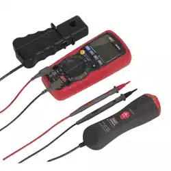
Includes new generation, 15-function, auto-ranging automotive diagnostic multimeter with IR thermometer attachment. Combination
digital/bar-graph display gives accurate indication of component outputs. large, easy to read high contrast display with bright, white
backlight. Workshop-tough, durable bi-composite case with integral stand and auto power shut-off. High speed processing circuitry
reads standard automotive parameters including duty cycle and pulse width making this tool ideal for testing fuel injection systems.
Features auto-ranging, and data hold functions with overload protection on all ranges. Includes relative functions including Min/Max
and Peak Hold. Supplied with Inductive Coupler, Infrared temperature probe, test probes and thermocouple in carry case.
3. specification
specification:................................................................ model no: ta304
Tach (RPM): .......... 2-10cyl, 4-Stroke 600-4000 (x1)rpm, 600-12000 (x10)rpm
dwell: ............................................................................................... 4/5/6/8cyl
AC Voltage: ...........................................................400mV, 4V, 40, 400V, 700V
dC Voltage: .........................................................400mV, 4V, 40, 400V, 1000V
AC Current: ...................................... 400µA, 4000µA, 40mA, 400mA, 4A, 20A
dC Current: ...................................... 400µA, 4000µA, 40mA, 400mA, 4A, 20A
Capacitance: ............................... 40nF, 400nF, 4µF, 40µF, 400µF, 4mF, 40mF
Frequency: .......................................................................... 0.001Hz-9.99MHz
duty Cycle: ...................................................................................... 0.1-99.9%
Pulse Width: ...................................................................................... 0.1-10ms
Resistance: ......................................... 400Ω, 4kΩ, 40kΩ, 400kΩ, 4MΩ, 40MΩ
Continuity: ......................................................... <30Ω Continuity Buzzer 2kHz
Temperature: ...................................................... -20 to +760°C, -4 to +1400°F
IR Temperature: ...................................................-20 to +280°C, -4 to +536°F
diode Check: .............................................................................................Yes
Back light: .................................................................................................Ye s
Bar Graph display: ..................................................................................... n/A
display Hold: .............................................................................................. Yes
Auto Ranging: ............................................................................................Yes
Inductive Coupler: ......................................................................................Yes
digits Height: ..........................................................................................20mm
Auto Power off: .......................................................................................... Yes
function terminal input limit
dC/AC Volts, 1 ohm/Continuity/diode,
CAP., IR-TeMP. Adaptor, Type-K TeMP.,
Hz, % duty, Ms dwell, RPM
V-Ω-RPM
600VoltsAC dC
AC/dC μA / mA 400mA dC/AC
AC/dC20A 20A *20A dC/AC
* 20 Amp measurement for 30 seconds maximum.
1 ohms can not be measured if voltage is present, ohms can be measured only in a non-powered circuit. However, the meter is protected to
600 volts.
TA304 Issue 5(HF) 24/09/18
Original Language Version
© Jack Sealey limited
low Battery Indicator: ................................................................................Yes
Batteries (supplied): .......................................................................... 9V (PP3)
Hi-Impact Case: .........................................................................................Yes
Size (l x W x d): .................................................................. 182 x 82 x 55mm
Weight: .....................................................................................................360g
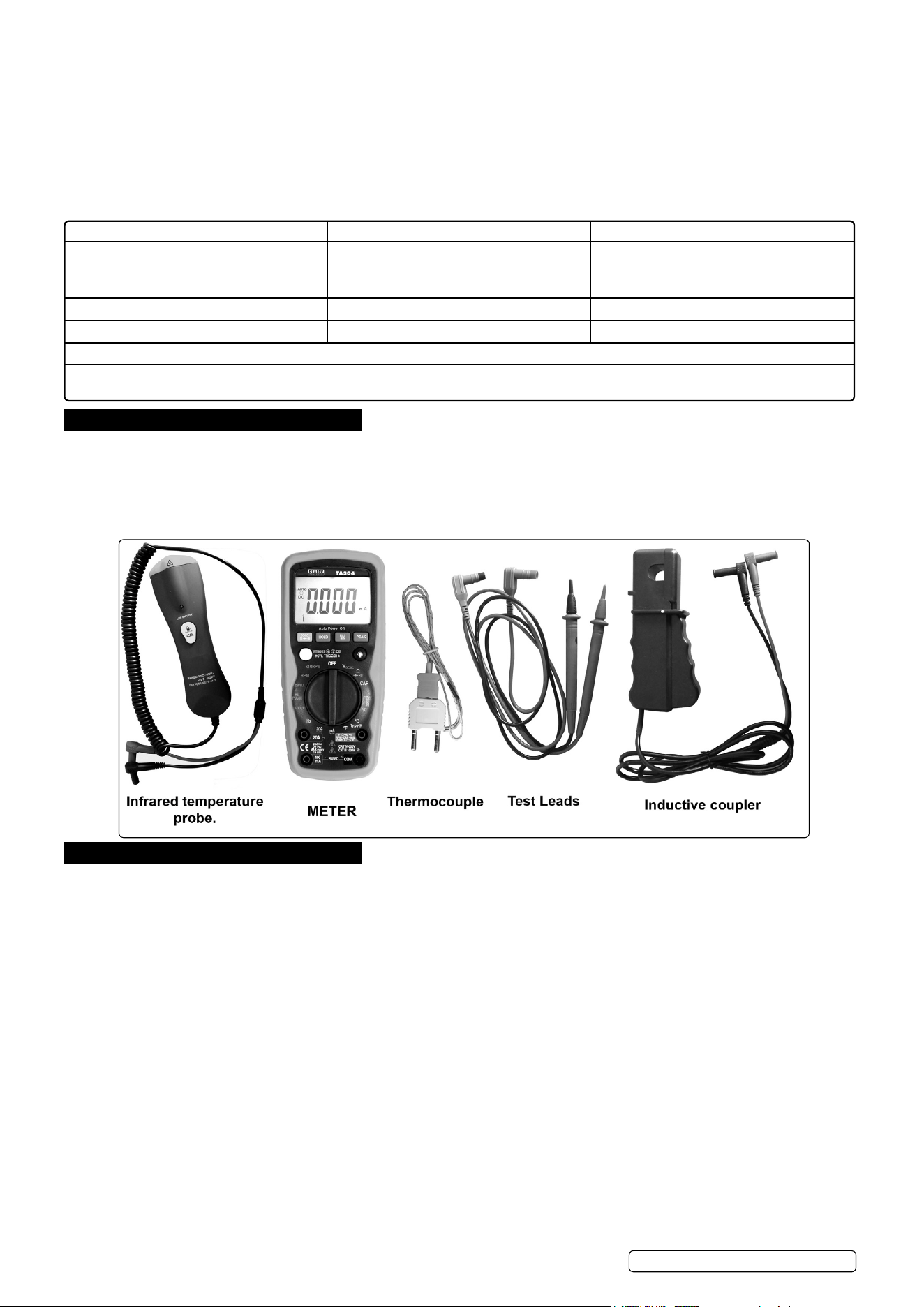
4. main meter features
5. push button functions
5.1. manual range & stroke 4/2(Dis), hz, %, ms +, cyl button
Press to this button to select; STROKE 4, 2DIS, Hz ,%, ms+, CYL range & V/A/ Resistance manual Range
5.1.1. manual ranging
The meter turns on in the autoranging mode. Press the Range button to go to manual ranging. The display icon “ “ will appear.
each press of the range button will step to the next range as indicated by the units and decimal point location. Press and hold the
Range button for two seconds to return to autoranging.
5.2. moDe button
Press the mode push button to select the following functions;
DC/AC Voltage, DC/AC Current Resistance, Diode, Continuity & Capacitance
TA304 Issue 5(HF) 24/09/18
Original Language Version
© Jack Sealey limited
g.1
g.2
g.3
g.4
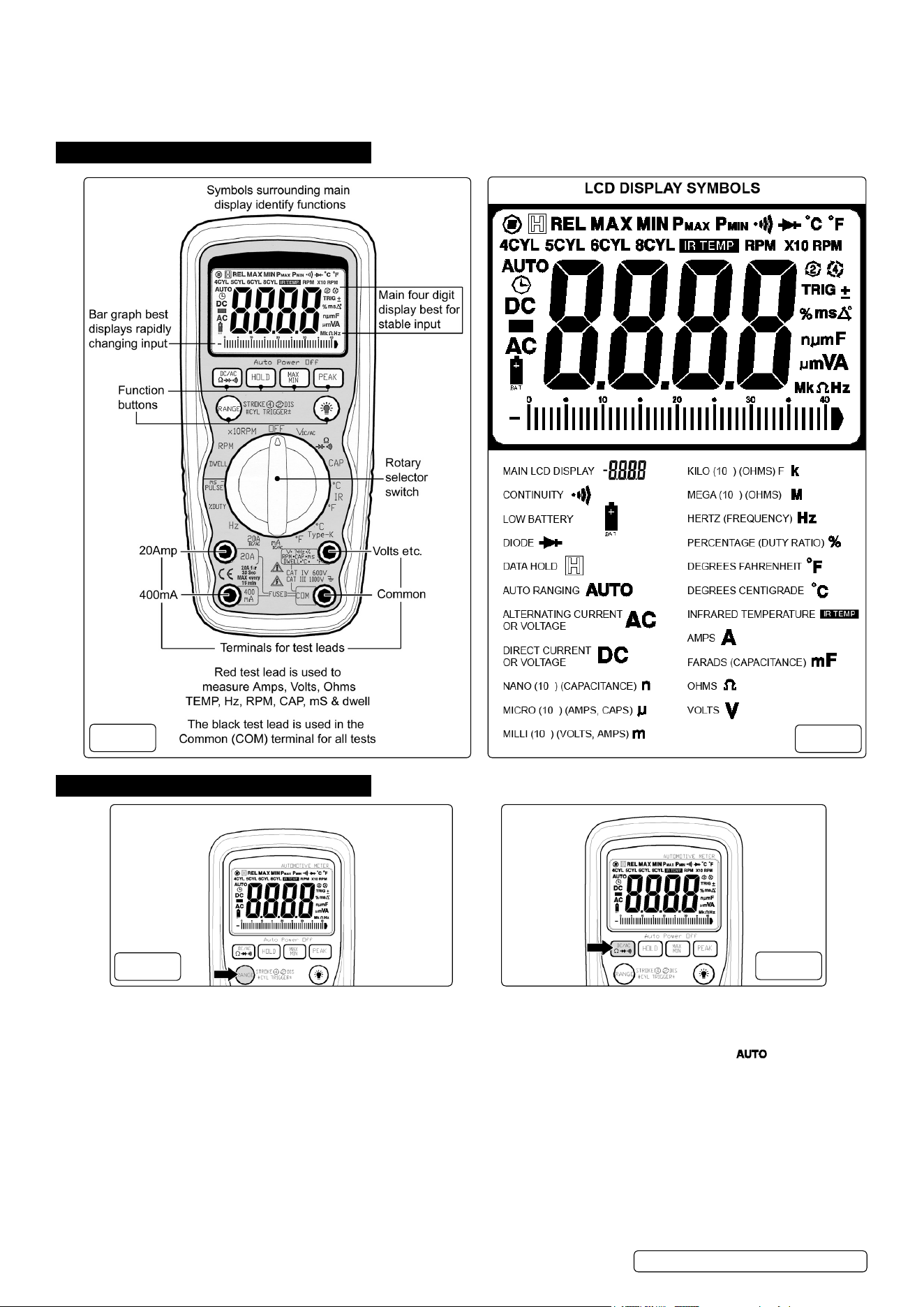
5.3. Data holD (g.5a)
The data Hold function allows the meter to “freeze” a measurement for later reference.
5.3.1. Press the dATA Hold button to “freeze” the reading on the display. The “Hold” symbol will appear in the display.
5.3.2. Press the dATA Hold button again to return to normal operation.
5.4. peak holD (g.5b)
The Peak Hold function captures the peak AC or dC voltage or current. The meter can capture negative or positive peaks as fast as 1
millisecond in duration.
5.4.1. Turn the function switch to the A or V position.
5.4.2. Press and Hold the PeAK button until “CAl” appears in the display. This procedure will zero the range selected & return the meter to
manual ranging.
5.4.3. Press the PeAK button, Pmax will display.
5.4.4. The display will update each time a higher positive peak occurs.
5.4.5. Press the PeAK button again, Pmin will display. The display will now update and indicate the lowest negative peak.
5.4.6. To return to normal operation, press and hold the PeAK button until the Pmin or Pmax indicator switches off. note: If the Function
switch position is changed after a calibration the Peak Hold calibration must be repeated for the new function selected.
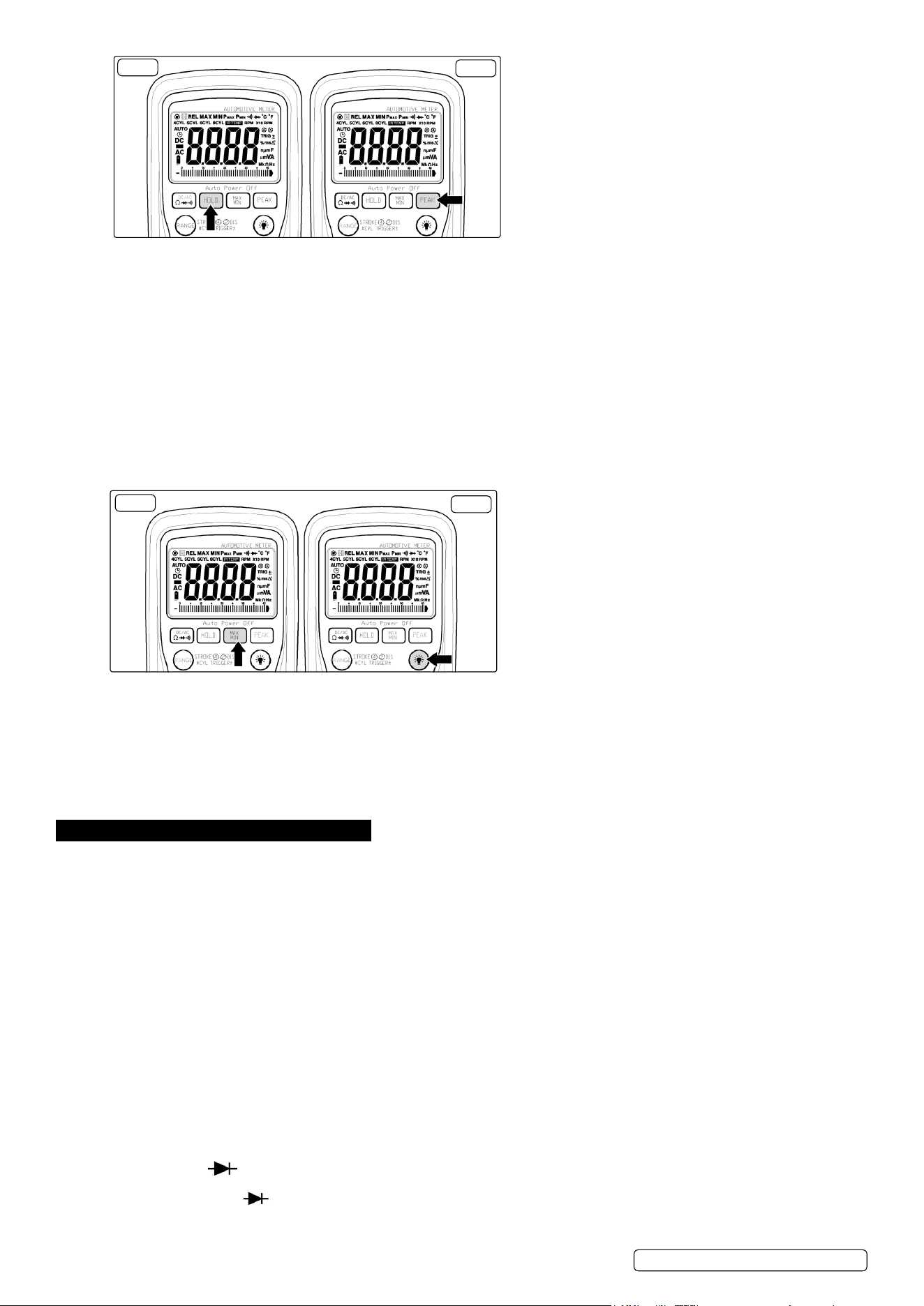
5.5. maX/min button (g.6a)
5.5.1. Press the MAX/MIn button to activate the MAX/MIn recording mode. The display icon “MAX or MIn” will appear. The meter will go to
manual ranging & display and hold the maximum or minimum reading and will update only when a new “max or min” occurs.
5.5.2. Press the MAX/MIn key and a blinking “MAX MIn” will appear. The meter will display the present reading, but will continue to update
and store the max and min readings. To exit MAX/MIn mode press and hold the MAX/MIn key for 2 seconds.
5.6. backlight button (g.6b)
5.6.1. Press the BACKlIGHT button to turn the backlighting on.
5.6.2. Press the BACKlIGHT button again to turn the backlighting oFF.
6. meter functions
6.1. voltage (v)
6.1.1. Select the volts “ v” range with the rotary switch.
6.1.2. The meter will automatically select the best voltage (V) range.
6.1.3. Select dCV or ACV with the moDe button.
6.1.4. Insert Black lead in com terminal.
6.1.5. Insert Red lead in V-Ω-RPM terminal
6.1.6. Touch the Black probe to ground or to the negative (-) circuit.
6.1.7. Touch the Red probe to the circuit coming from the power source.
▲ important: voltage must be measured in parallel (red probe measuring circuit from power source).
warning: when measuring voltage, be sure the red test lead is in the terminal marked “v”. if the test lead is in an amp (a)
or milliampere (ma) terminal, you may be injured or the meter damaged.
6.2. resistance (Ω)
▲ important: If you are testing an application that has capacitors in the circuit, be sure to turn the power oFF on the test circuit and discharge
all capacitors. Accurate measurement is not possible if external or residual voltage is present.
6.2.1. Select the resistance “ Ω” range with the rotary switch.
6.2.2. Select the resistance “Ω” function with the Mode button. Please note, the unit defaults to resistance.
6.2.3. Insert Black lead in com terminal.
6.2.4. Insert Red lead in V-Ω-RPM terminal
6.2.5. Touch the test lead probes across the resistor to be tested.
6.3. DioDe check ( )
▲ important: turn the power off to the test circuit
6.3.1. Select the diode Check “ “ function with the rotary switch and mode button.
6.3.2. Insert Black lead in com terminal.
6.3.3. Insert Red lead in V-Ω-RPM terminal
g.5a
g.5b
g.6a
g.6b
TA304 Issue 5(HF) 24/09/18
Original Language Version
© Jack Sealey limited

6.3.4. Touch the Black test probe to the negative (-) side of the diode.
6.3.5. Touch the Red test probe to the positive (+) side of the diode.
6.3.6. Reverse the probes: Black to the positive (+) side and Red to the negative (-) side.
note: A “good” diode will read low in one `direction and high in the other direction when the probes are reversed (or vice versa).
A defective diode will have the same reading in both directions or read between 1.0 to 3.0 V. in both directions
6.4. capacitance (cap)
important: turn the power off to the test circuit
6.4.1. Select the Capacitance “ cap “ function with the rotary switch and mode button.
6.4.2. Insert Black lead in com terminal.
6.4.3. Insert Red lead in V-Ω-RPM terminal.
caution: when checking in-circuit capacitance, be sure that the circuit has all power removed and all capacitors are fully
discharged.
6.4.4. Touch the test lead probes across the capacitance circuit to be tested.
6.4.5. Read the measured value from the lCd display.
note: (a) The bar graph is disabled in capacitance measurement mode.
However, since the measurement time of 4mF and 40mF modes is quite long (3.75s and 7.5s respectively, to be precise,) the bar graph
is used to display the time rest to accomplish the measurement.
(b) In order to obtain an accurate reading, a capacitor must be discharged before measurement begins. The meter has a built-in
discharge mode to automatically discharge the capacitor. In discharge mode, the lCd displays “dIS.C”
(c) discharging through the chip is quite slow. We recommend the user to discharge the capacitor with some other apparatus.
6.5. auDible continuity ( )
▲ important: turn the power off on the test circuit
6.5.1. Select the Audible Continuity “ “ function with the rotary switch and mode button.
6.5.2. Insert Black lead in com terminal.
6.5.3. Insert Red lead in V-Ω-RPM terminal.
6.5.4. Connect one test probe to each end of the circuit to be tested.
6.5.5. If the circuit is complete, the meter will beep continuously.
6.5.6. If the circuit is open, there is no beep and the display shows ol (over limit).
6.6. ac or Dc current (a)
important: all current measured flows through the meter.
it is important that you Do not:
(a) measure current greater than 600 volts ac or Dc, with respect to ground.
(b) Do not exceed 30 seconds when measuring continuous current between 1a-20a. allow five minutes for cool down before
continuing.
6.6.1. Select the “20A” or “mA” range with the rotary switch.
6.6.2. Press the Mode button to select AC or dC.
6.6.3. Insert the black lead into the CoM terminal.
6.6.4. Insert the red lead into the 20A or mA terminal (select 20A if you are unsure of the current draw).
important: turn off all power to the circuit or disconnect the circuit from the power source.
6.6.5. Connect the Red probe to the side of the circuit closest to the power source.
6.6.6. Connect the Black probe to the side of the circuit to ground.
6.6.7. Turn the power on and test.
note: current must always be measured with the meter test probes connected in series, as described.
6.7. temperature (ºc/ºf)
important: to avoid heat damage to the meter, keep it away from sources of very high temperature. the life of the
thermocouple probe is also reduced when subjected to very high temperatures. probe operating range is –58º to 482 ºf.
6.7.1. Select the Temperature ºc or ºf function with the rotary switch.
6.7.2. Insert the thermocouple probe connector into the K-type thermocouple adapter. Insert the adapter into the front of the meter with the
negative pin in the CoM terminal socket. Touch the end of the thermocouple temperature sensor to the area or surface of the object to
be measured.
6.8. freQuency(hz)
6.8.1. Select the “hz” Frequency function with the rotary switch.
6.8.2. Insert the black lead into the com terminal.
6.8.3. Insert the red lead into the V-Ω-RPM terminal.
6.8.4. Connect the Black test probe to ground.
6.8.5. Connect the Red test probe to the “signal out” wire of the sensor to be tested.
6.9. Dwell angle ( )
6.9.1. Select the “dWell” function with the rotary switch.
6.9.2. Insert the Black lead into the CoM terminal.
6.9.3. Insert the Red lead in V-Ω-RPM terminal.
6.9.4. Connect the Black test probe to ground.
6.9.5. Connect the Red test probe to the wire that connects to the breaker points (see g.7).
6.10. Duty cycle (%)
DioDe (- to +) reverse probes (+ to -)
Good
0.4 to 0.9V over limit (ol)
over limit (ol) 0.4 to 0.9V
BAd
over limit (ol) 1.0 to 3.0V
1.0 to 3.0V over limit (ol)
0.4 to 0.9V 0.4 to 0.9V
over limit (ol) over limit (ol)
0.000V 0.000V
TA304 Issue 5(HF) 24/09/18
Original Language Version
© Jack Sealey limited
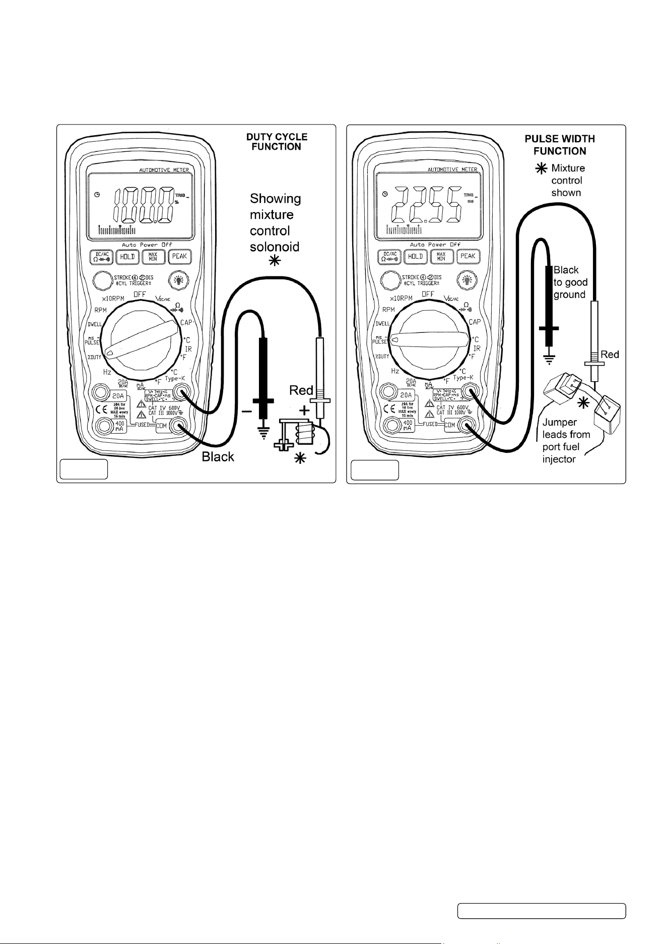
6.10.1. Select the “% duty Cycle” function with the rotary switch.
6.10.2. Insert the black lead into the com terminal.
6.10.3. Insert the red lead into the V-Ω-RPM terminal.
6.10.4. Connect the Black test probe to ground.
6.10.5. Connect the Red test probe to the signal wire circuit.
note: The illustration for a mixture control solenoid is shown with the metering rod in the closed position. The meter will display the percentage
of time the plunger is in the closed position during one duty cycle.
6.11. ms-pulse (pulse width) & ms- perioD (period)
6.11.1. Pulse Width is the length of time an actuator is energized. For example, fuel injectors are activated by an electronic pulse from the
Engine Control Module (ECM). This pulse generates a magnetic eld that pulls the injector nozzle valve open. The pulse ends
and the injector nozzle is closed. This open to close time is the Pulse Width and is measured in milliseconds (ms). The most common
automotive application for measuring pulse width is on fuel injectors. You can also measure the pulse width of the fuel mixture control
solenoid and the idle air control motor.
this exercise shows how to measure pulse width (ms) on port fuel injectors. (see fig.8)
6.11.2. Select the “mS-Pulse” function with the rotary switch .
6.11.3. Press the Trigger± button for 2 seconds until the negative (-) trigger slope is displayed on the upper left side of the display.
note: The applied time for most fuel injectors is displayed on the negative (-) slope.
6.11.4. Insert the black lead into the com terminal.
6.11.5. Insert the red lead into the V-Ω-RPM terminal.
6.11.6. Connect jumper wires between the fuel injector and the harness connector.
6.11.7. Touch the Black test probe to a good ground at the fuel injector or the negative (-) vehicle battery post.
6.11.8. Touch the Red test probe to the fuel injector solenoid driver input on the jumper cable.
6.11.9. Start the engine. A pulse width in milliseconds should be read.
note: Initially, the unit will read “ol”, then readings will descend and stabilize to the actual pulse.width. If “ol” remains, re-check your
connections.
g.7
g.8
TA304 Issue 5(HF) 24/09/18
Original Language Version
© Jack Sealey limited
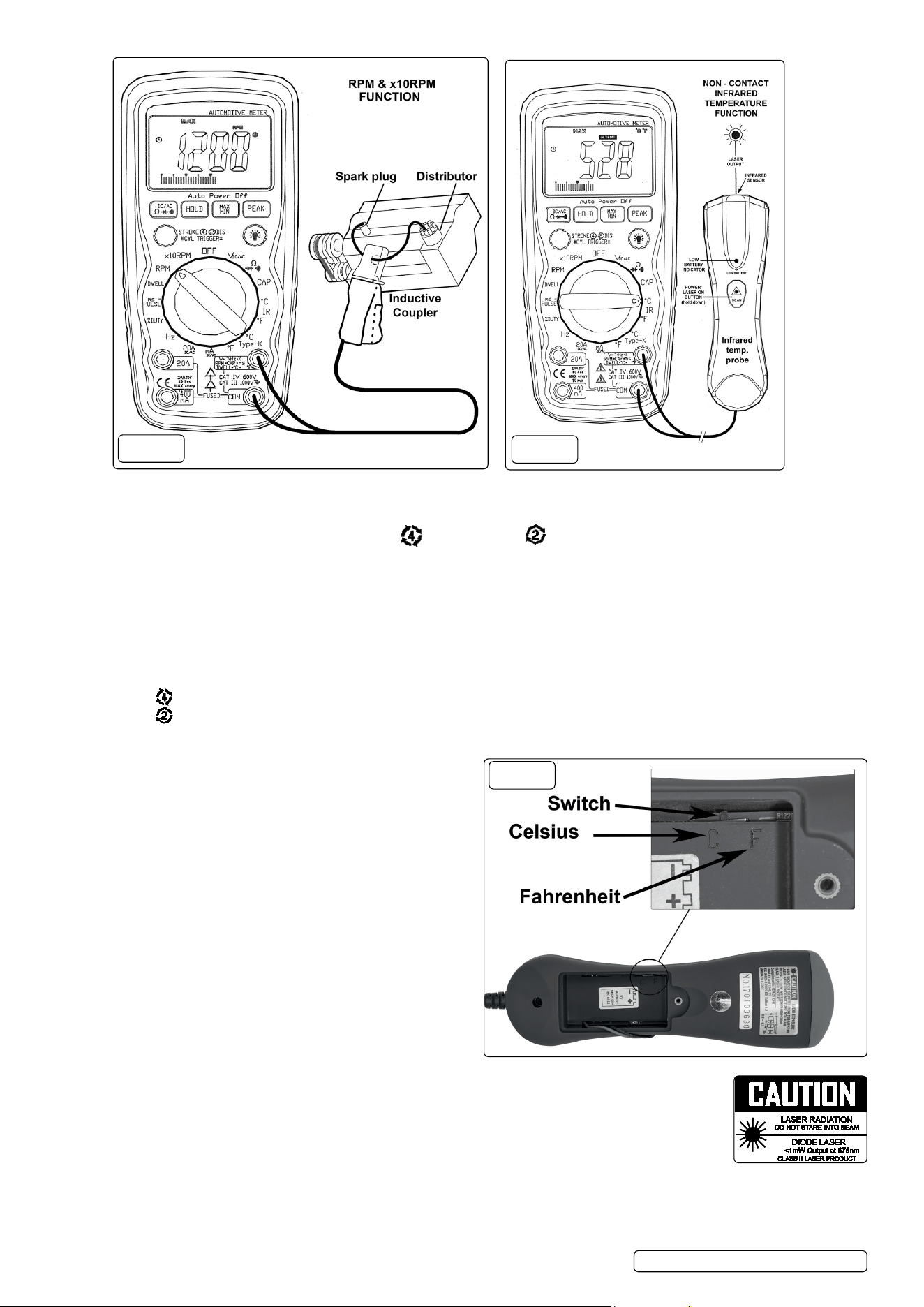
6.12. rPM and ×10RPM (See g.9)
6.12.1. Using the rotary switch, select either the rpm range or the ×10rpm range (1,000 to 12,000 RPM) and multiply the displayed reading
by ten to get actual RPM.
6.12.2. Press STRoKe / dIS button to select through RPM for 4-stroke, RPM for 2-stroke and dIS ignitions.
6.12.3. Connect the inductive coupler leads to the meter.
6.12.4. Insert the black lead into the com terminal.
6.12.5. Insert the red lead into the V-Ω-RPM terminal.
6.12.6. open the inductive coupler and place it onto a spark plug wire. If no reading is received, unhook the clamp, turn it over and connect
again.
notes:
6.12.7. Position the inductive coupler as far away from the distributor and the exhaust manifold as possible.
6.12.8. Position the inductive coupler to within six inches of the spark plug or move it to another plug wire if no reading or an erratic reading is
received.
6.12.9. rpm 4 : For RPM of 4-stroke engines which have 1 ignition on every 4 engine strokes
6.12.10. rpm 2 : For RPM of dIS ( distributorless lgnition System) & 2-stroke engines which Have 1 ignition on every 2 engine strokes
PleASe noTe - THe RPM IndUCTIVe CoUPleR HAS An AdJUSTABle SenSITIVITY SWITCH THAT CAn AlSo Be USed To
CoRReCT An UnSTABle ReAdInG.
6.13. infrareD temperature probe introDuction
laser safety (fig.11)
9 use extreme caution when the laser beam is turned on.
8 Do not let the beam enter your eye, another person’s eye or
the eye of an animal.
8 Do not let the beam strike your eye from a reective surface.
6.13.1. The Infrared Temperature Probe is a non-contact temperature
measurement accessory for use with a test instrument
capable of measuring dC volts in the millivolt range
(200mv/400mv/600mv/2v/4v/6v range). The probe has
a temperature range of -30°C to 550°C (-22°F to 1022°F), with
a basic accuracy of 2% of reading, and an output of 1 mv dC
per °C or °F. Temperature is measured by pointing the probe at
the surface to be measured, and reading the temperature on the
test instrument display. Celsius or Fahrenheit is selected by
moving the selector situated in the battery box (see g.11).
6.13.2. compatibility
The probe is compatible with the automotive meter’s InfraRed
Temperature (°C or °F) ranges that have a minimum of 1 MΩ input
impedance and accept safety shrouded, standard diameter 0.16
in. (4 mm) banana plugs.
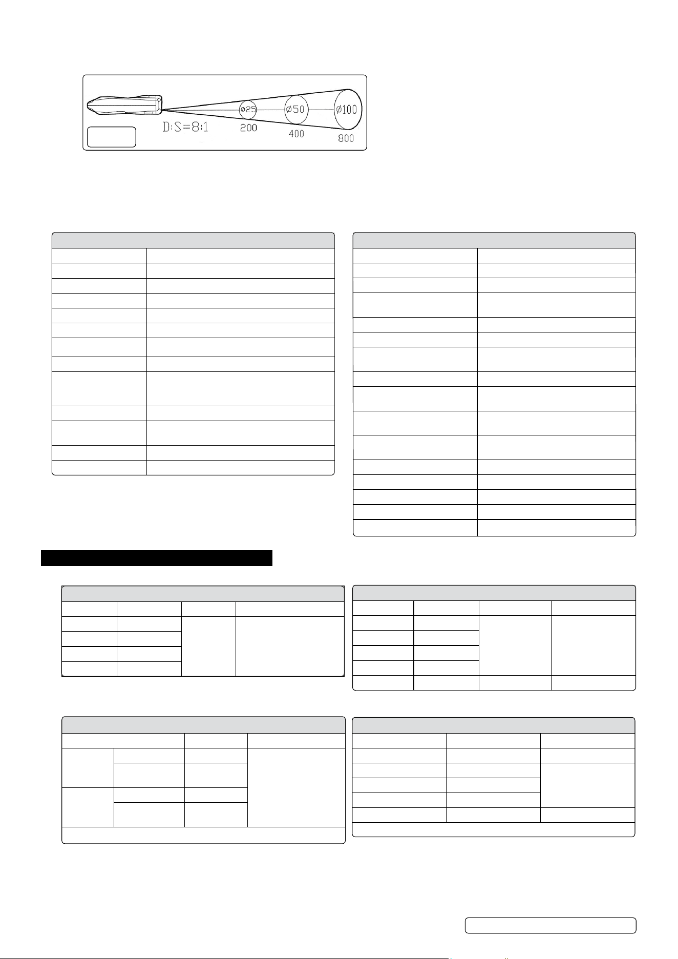
6.13.3. field of view
The meter’s field of view is 8:1, meaning that if the meter is 8 inches from the target, the diameter of the object
under test must be at least 1 inch. other distances are shown below in the field of view diagram. Refer to the
chart printed on the meter for more information. Make sure that the target is larger than the unit’s spot size. The
smaller the target, the closer you should be to it. When accuracy is critical, make sure the target is at least
twice as large as the spot size.
6.13.4. operation
To take a measurement, perform the following steps:
6.13.5. Insert the black lead into the com terminal and the red lead into the V-Ω-RPM terminal.
6.13.6. Select InfraRed Temperature (°C-IR-°F) on the test instrument.
g.9
g.10
TA304 Issue 5(HF) 24/09/18
Original Language Version
© Jack Sealey limited
g.11
6.13.7. Press and hold down the probe laser button to turn on the laser.
6.13.8. Point the tip of the probe as close as possible to the object being measured without touching the object.
6.13.9. Read the test instrument display.
note: infrared measurement considerations.
Holding the laser unit in your hand, direct the laser/infrared probe toward the object whose temperature is to be measured bearing in
mind the field of view requirements shown in fig.12. The meter automatically compensates for temperature deviations due to the ambient
temperature. If a higher temperature is to be measured after taking a low temperature measurement, it is advisable to wait several
minutes between the measurements for the infrared sensor to cool. Keep in mind that it may take up to 30 minutes to adjust to wide
ambient temperature differences.
7. electrical specifications
infrareD temperature probe specification
Response rate 0.5 seconds approx.
operating temperature 32ºF to 122ºF (0ºC to 50ºC)
operating Humidity Max 80% RH.
Power Supply 9V battery (PP3)
Weight 182g
Size 164 x 50 x 40mm
IR Thermometer range -30 to 550ºC (-22ºF to 1022ºF)
IR Thermometer output 1mV = 1ºC or 1ºF
IR Thermometer
accuracy
± 2% of reading or 4ºF whichever is greater. note:
accuracy is specified for the following ambient
temperature range: 64 to 82ºF (18 to 28ºC)
emissivity 0.95 fixed value
Field of view d/S Approx. 8.1 (d = distance & S = spot) Has
90% encircled energy at focal point.
laser Power less than 1mW
Spectral response 6 to 14 µm (wavelength)
general instrument specification
Instrument complies with IeC 1010-1 en61010-1
Insulation Class 2, double Insulation
overvoltage category CATIII1000V/CATIV600V
display 4000 counts lCd display with
function indication
Polarity Automatic, (-) negative polarity indication.
overrange "ol" marks indication
low battery indication "BAT" is displayed when the battery
voltage drops below the operating level
Measurement rate 2 times per second, nominal
Auto power off Meter automatically shuts down after
approx. 30 seconds of inactivity
operating environment 0ºC to 50ºC (32ºF to 122ºF) at < 70%
relative humidity.
Storage temperature -20ºC to 60ºC (-4ºF to 140ºF) at < 80%
relative humidity.
For inside use, max height 2000m
Pollution degree 2
Power one 9V battery (PP3)
dimensions 182 x 82 x 55mm
Weight 360g
Dwell angle
cylinder range resolution accuracy
4CYl 0 ~ 90.0º
0.1º ±2% of rdg ± 4dgts
5CYl 0 ~ 72.0º
6CYl 0 ~ 60.0º
8CYl 0 ~ 45.0º
electrical specification (accuracy). Accuracy is given as ± ([%
of reading] + [number of least significant digits]) at 18ºC to 28ºC (65ºF
to 83ºF), with relative humudity up to 70%.
rpm (Tach)
range resolution accuracy
RPM4 600 ~ 4000 RPM 1 RPM
±2% of rdg ± 4dgts
1000 ~ 12000
RPM. (x10 RPM)
10RPM
RPM 2/dIS 300 ~ 4000 RPM 1 RPM
1000 ~ 6000
RPM. (x10 RPM)
10RPM
effect Reading: >600RPM
freQuency
range resolution sensitivity accuracy
4.000kHz 1Hz
40.00kHz 10Hz >5V RMS ±1.5% of rdg ± 3dgts
400.0kHz 100Hz
4.000MHz 1000Hz
40.00MHz 1kHz >15V RMS ±2.0% of rdg ± 4dgts
Dc voltage
range resolution accuracy
400.0mV 0.1mV ±0.5% of rdg ± 3dgts
4.000V 1mV
±1.5% of rdg ± 2dgts
40.00V 10mV
400.0V 100mV
600V 1V ±1.8% of rdg ± 2dgts
Input Impedance: 10MΩ
TA304 Issue 5(HF) 24/09/18
Original Language Version
© Jack Sealey limited
g.12

8. maintenance
warning! Do not attempt to repair or service the analyser unless you are qualified to do so and have the relevant calibration,
performance test, and service information. To avoid electrical shock or damage to the meter do not get water inside the case.
8.1. Periodically wipe the case with a damp cloth and mild detergent. Do not use solvents.
8.2. Turn the analyser off when not in use and remove the battery if stored for a long period of time.
8 Do not store the analyser in a place of high humidity or high temperature.
8.3. replacing the battery
warning! To avoid electric shock, disconnect the test leads from the analyser before removing the battery cover.
8.3.1. When the battery becomes exhausted or drops below the operating voltage, the battery symbol will be appear in the left hand side of the
display.
8.3.2. open the battery cover by loosening the two screws using a small cross head screwdriver.
8.3.3. Remove the old battery and insert the new one, observing the correct polarity.
8.3.4. Replace the battery cover and secure with the two screws.
warning! To avoid electric shock, Do not operate the analyser until the battery cover is secured in place.
8.4. replacing the fuses
warning! To avoid electric shock, disconnect the test leads from the analyser before accessing the fuses.
8.4.1. open the rear cover by loosening the six screws using a small cross head screwdriver. Gently ease the rear cover off.
8.4.2. Remove the old fuse from its holder by gently pulling it out. Take care not to touch any other internal parts of the analyser.
8.4.3. Install the new fuse into its holder by gently pushing it in.
note: Always use a fuse of the correct size and value.
fuse ratings:
20A/250V, 6.3 x 32mm fast acting ceramic type for the 20A range.
0.5A/250V, 5 x 20mm fast acting ceramic type for the 400mA range.
8.4.4. Replace the rear cover and secure with the six screws.
warning! To avoid electric shock, Do not use the analyser until it has been fully re-assembled.
ac voltage
range resolution accuracy
400.0mV 0.1mV ±1.5% of rdg ± 5dgts
4.000V 1mV ±1.0% of rdg ± 3dgts
40.00V 10mV ±1.5% of rdg ± 3dgts
400.0V 100mV
600V 1V ±2.0% of rdg ± 4dgts
Input Impedance: 10MΩ / Frequency Range 50 to 60Hz
Dc current
range resolution accuracy
40.00mA 10uA ±1.5% of rdg ± 3dgts
400.0mA 100uA
20A 10mA ±2.5% of rdg ± 5dgts
overload Protection: 0.5A / 250V and 20A / 250V Fuse
Maximum Input: 400mA dC or 400mA AC RMS on uA / mA ranges,
20A dC or AC RMS on 20A range.
resistance
range resolution accuracy
400.0Ω 0.1Ω ±1.2% of rdg ± 4dgts
4.000kΩ 1Ω ±1.0% of rdg ± 2dgts
40.00kΩ 10Ω
400.0kΩ 100Ω ±1.2% of rdg ± 2dgts
4.000MΩ 1kΩ
40.00MΩ 10kΩ ±2.0% of rdg ± 3dgts
ac current
range resolution accuracy
40.00mA 10uA ±1.8% of rdg ± 5dgts
400.0mA 100uA
20A 10mA ±3.0% of rdg ± 7dgts
capacitance
range resolution accuracy
4.000nF 1pF ±5.0% of rdg ± 50dgts
40.00nF 1pF ±5.0% of rdg ± 7dgts
400.0nF 0.1nF
4.000uF 1nF ±3.0% of rdg ± 5dgts
40.00uF 10nF
400.0uF 0.1uF
4.000mF 0.001mF ±10% of rdg ± 10dgts
40.00mF 10.00mF
type k temperature
range resolution accuracy
-30°C ~ 1000°C 1.0°C ± 3 % of rdg ± 5°C/8°F
-22°F ~ 1832°F 1.0°F (Meter only)
pulse wiDth
range resolution accuracy
1.0 ~ 20.0ms 0.1ms ± 2% of rdg ± 20dgts
DioDe test
test current resolution accuracy
1.0mA typical 1mV ±5% of rdg ± 15 dgts
open circuit voltage: 3.0V dC typical
Duty cycle
range resolution accuracy
0.5% ~ 99.0% 0.1% ± 2% of rdg ± 5dgts
auDible continuity test
Audible threshold: < 35Ω
Test Current: < 1mA dC typical
TA304 Issue 5(HF) 24/09/18
Original Language Version
© Jack Sealey limited
Pulse width: >100us, <100ms
Frequency width: 5Hz ~ 100kHz
Sensitivity: >5V RMS
overload Protection: 0.5A / 250V and 20A / 250V Fuse
Frequency Range: 50 to 60Hz
Maximum Input: 400mA dC or 400mA AC RMS on uA / mA ranges,
20A dC or AC RMS on 20A range.
TA304 Issue 5(HF) 24/09/18
Original Language Version
© Jack Sealey limited
sealey group, kempson way, suffolk business park, bury st edmunds, suffolk. ip32 7ar
01284 757500 01284 703534 sales@sealey.co.uk www.sealey.co.uk
environment protection
Recycle unwanted materials instead of disposing of them as waste. All tools, accessories and packaging should be sorted, taken to
a recycling centre and disposed of in a manner which is compatible with the environment. When the product becomes completely
unserviceable and requires disposal, drain any fluids (if applicable) into approved containers and dispose of the product and fluids
according to local regulations.
weee regulations
dispose of this product at the end of its working life in compliance with the eU directive on Waste electrical and electronic equipment
(Weee). When the product is no longer required, it must be disposed of in an environmentally protective way. Contact your local solid
waste authority for recycling information.
battery removal see section 8.4
Under the Waste Batteries and Accumulators Regulations 2009, Jack Sealey ltd are required to inform potential purchasers of products
containing batteries (as defined within these regulations), that they are registered with Valpak’s registered compliance scheme. Jack
Sealey ltd Batteries Producer Registration number (BPRn) is BPRn00705.
note: It is our policy to continually improve products and as such we reserve the right to alter data, specifications and component parts without prior
notice.
important: no liability is accepted for incorrect use of this product.
warranty: Guarantee is 12 months from purchase date, proof of which is required for any claim.