Loading ...
Loading ...
Loading ...
CONTROLS & OPERATION
6
NOTE: This Operator’s Manual covers several models. Features may vary by model. Not all features in this
manual are applicable to all models and the model depicted may differ from yours.
Engine Controls
See the Engine Operator’s Manual for the location and function of the controls on the engine.
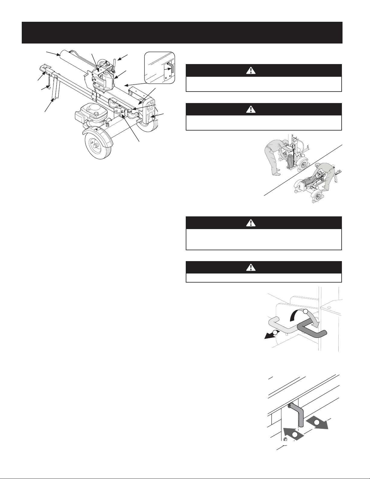
Beam Locks
The beam locks are used to secure the beam in either the horizontal position or the vertical
position. The vertical beam lock is located next to the engine. The horizontal beam lock is
located on the beam support latch bracket.
Control Handle
Use the control handle to move the log splitter wedge forward and backward along the
beam. It has three positions; FORWARD, NEUTRAL and REVERSE. See Using the Control
Handle section for instructions.
Wedge
The wedge is used to split the wood.
Log Dislodger
The log dislodger is designed to remove any partially split wood from the wedge while it is
retracting. This may occur while splitting large diameter wood or freshly cut wood.
Log Tray
The log tray is designed to stabilize the log after it is split.
Tongue
The tongue is used to attach to a towing vehicle for transportation.
End Plate
The end plate holds the log in place while the wedge splits it.
Safety Chains
The safety chains are hooked to the towing vehicle for transportation.
NOTE: This Operator’s Manual covers several models. Features may vary by model. Not all features in this
manual are applicable to all models and the model depicted may differ from yours.
Pre-Start Checklist
1. Remove the vented dipstick and check hydraulic fluid level. Refill if necessary.
Approved fluids include Shell Tellus® S2 M 32 Hydraulic Fluid, Dexron® III/Mercon®
Automatic Transmission Fluid, Pro-Select™ AW-32 Hydraulic Oil or 10WAW-ISO
Viscosity Grade 32 Hydraulic Oil.
2. Check the engine oil level. Refill if necessary.
3. Fill up with gasoline if necessary.
4. Lubricate the beam area where the splitting wedge will slide with engine oil using
a clean rag. Do not use grease to lubricate. Make sure to lubricate both the front and
the back of the beam face.
5. Attach the spark plug wire to the spark plug.
Starting the Engine
Refer to the Engine Operator’s Manual for detailed starting instructions.
WARNING
Read, understand and follow all the instructions and warnings on the machine and
included in the Operator’s Manuals before operating.
Using the Log Splitter
WARNING
Wear work gloves, safety shoes, ear protection and safety glasses when operating
the log splitter. Ensure safe footing.
Operating Positions
1. Place the log splitter on flat,
level, dry, solid ground.
2. Block the front and back of both
wheels. See Figure 13.
3. Place the beam in either the
horizontal or vertical position
and lock into place.
WARNING
Take extra care when raising and lowering the beam as it is heavy. Having a second
person assist with raising or lowering the beam is recommended. Be sure to keep
hands away from any possible pinch points.
4. To place the beam in the vertical position, proceed as follows:
WARNING
Always use the log splitter in the vertical position when splitting heavy logs.
a.
Pull the horizontal
beam lock out to
release the beam and
pivot the beam to the
vertical position.
b. To lock the beam in
the vertical position,
pull out on the vertical
beam lock and rotate it
to secure the beam. See
Figure 14.
5. To place the beam in the
horizontal position, proceed
as follows:
a. Pull the vertical beam
lock out and rotate it
down. Pivot the beam to
the horizontal position.
b. The horizontal beam
lock is self-locking. The
spring loaded lock will
snap into place when
the beam is lowered into
position. See Figure 15.
Horizontal
Vertical
Figure 13
Vertical Beam Lock
1
2
Figure 14
1
2
Horizontal Beam Lock
Figure 15
NEUTRAL
(To stop wedge)
FORWARD
(To split wood)
REVERSE
(To return wedge)
Figure 16
Horizontal
Beam Lock
Jack Stand
Tongue
Cylinder
Safety Chains
Log Dislodger
Wedge
Vertical Beam
Lock
Beam
Log Tray
End
Plate
Control
Handle
Figure 12
Loading ...
Loading ...
Loading ...