
Loading ...
Loading ...
Loading ...
ASSEMBLY & SET-UP
4
Thank You
Thank you for purchasing this product. It was carefully engineered to provide excellent performance
when properly operated and maintained.
Please read this entire manual prior to operating the equipment. It instructs you how to safely and
easily set up, operate and maintain your machine. Please be sure that you, and any other persons who
will operate the machine, carefully follow the recommended safety practices at all times. Failure to do
so could result in personal injury or property damage.
All information in this manual is relative to the most recent product information available at the time
of printing. Review this manual frequently to familiarize yourself with the machine, its features and
operation. Please be aware that this Operator’s Manual may cover a range of product specifications for
various models. Characteristics and features discussed and/or illustrated in this manual may not be
applicable to all models. We reserve the right to change product specifications, designs and equipment
without notice and without incurring obligation.
If applicable, the power testing information used to establish the power rating of the engine equipped
on this machine can be found at www.opei.org or the engine manufacturer’s web site.
If you have any problems or questions concerning the machine, phone your local authorized service
dealer or contact us directly. Customer Support telephone numbers, website address and mailing address
can be found in the separate supplement. We want to ensure your complete satisfaction at all times.
Throughout this manual, all references to right and left side of the machine are observed from the
operating position.
The engine manufacturer is responsible for all engine-related issues with regards to performance,
power-rating, specifications, warranty and service. Please refer to the engine manufacturer’s Owner’s/
Operator’s Manual, packed separately with your machine, for more information.
Contents of Carton
• Log Splitter
• Tongue Assembly
• Operator’s Manual
• Engine Operator’s Manual
WARNING
Use extreme caution unpacking this machine. Some components are very
heavy and will require additional people or mechanical handling equipment.
NOTE: All references in this manual to the left or right side and front or back of the log splitter are from
the operating position only. Exceptions, if any, will be specified.
IMPORTANT! A minimum of two people are recommended to assemble this unit.
Unpacking & Assembling the Log Splitter
TOOLS NEEDED: Safety glasses, leather gloves, wire cutters, pry bar and/or
claw hammer.
1. Use a pry bar or claw hammer to loosen and remove the top of the crate.
2. Use a pry bar or claw hammer to remove the sides of the crate, beginning
with the short sides (or left and right side of the log splitter). Set the sides of
the crate aside to avoid injury.
3. A cable tie attaches the tongue assembly to the inside, front of the crate. Cut
the cable tie to remove the tongue.
4. Remove the large plastic cover and discard.
WARNING
DO NOT remove any wood or cut any straps securing the log splitter or its
components to the log splitter or the crate at this time. Only remove straps
and/or wood when instructed to do so.
5. Inspect the bottom of the crate for any protruding staples or wood splinters
and remove.
6. Remove any loose parts
included with the log
splitter (i.e. Operator’s
Manual, etc.).
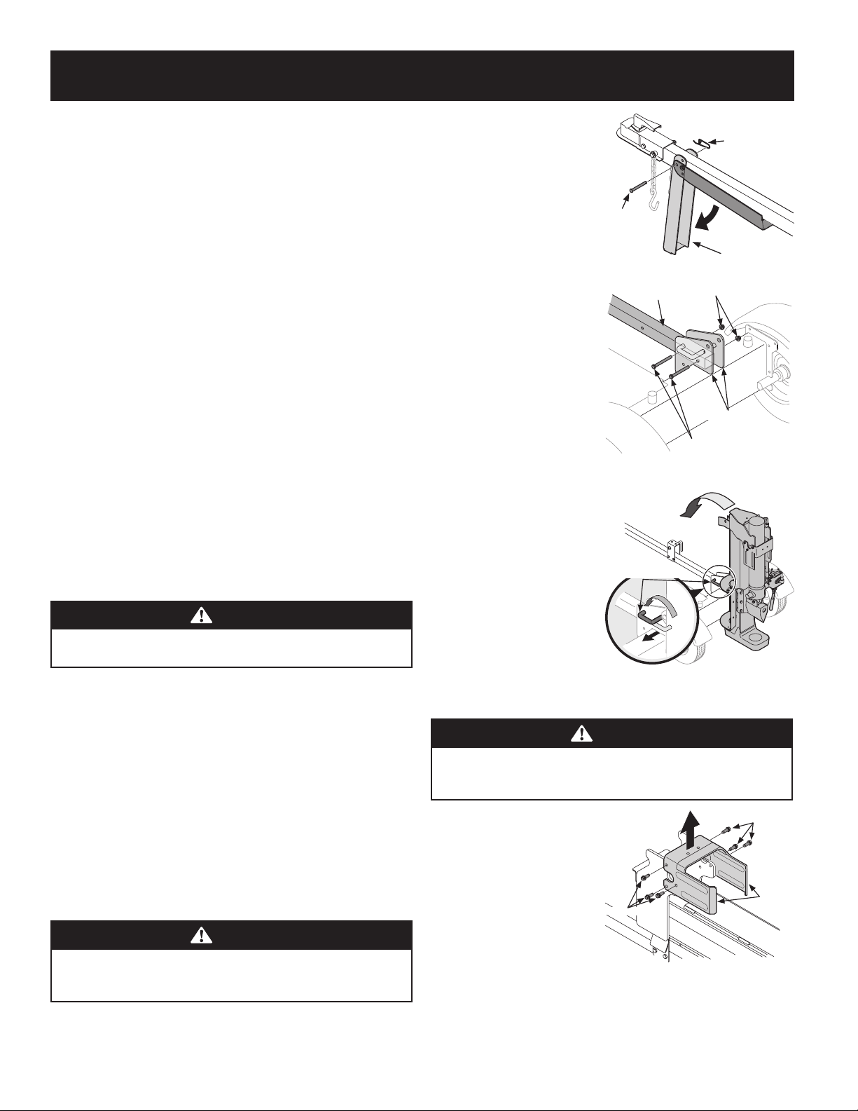
7. Remove the spring clip and
clevis pin from the jack
stand on the tongue and
then pivot the jack stand
towards the ground into the
operating position. See
Figure 2.
8. Secure the jack stand in
position with the clevis pin
and spring clip. See Figure 2.
9. With the log splitter still
secured to the bottom of
the crate, remove two hex
bolts and hex nuts from the
tank bracket and remove
the piece of wood inside the
tank brackets. See Figure 3.
10. Align the holes in the tongue
with the holes in the tank
bracket and secure with the
hardware just removed. See
Figure 3.
NOTE:
The high pressure hose,
which runs from the gear pump to
the bottom of the control valve,
must be above the tongue assembly.
11. The log splitter is shipped
with the beam in a vertical
position. Remove any bolts or
straps securing the end plate
to the bottom of the crate.
12. Pull out the vertical beam
lock, rotate it back and pivot
the beam to the horizontal
position until it locks. Be
sure to avoid any possible pinch points. See Figure 4.
WARNING
Take extra care when raising and lowering the beam as it is heavy. Having
a second person assist with raising or lowering the beam is recommended.
Be sure to keep hands away from any possible pinch points.
13. Remove the wood between
the wedge and the end
plate by cutting the cable
tie that secures it. Cut the
strap near the hose on the
front of the cylinder that
secures it to the beam weld
bracket. Be careful not to
damage the hose.
14. Disconnect the dislodger
from the beam weld bracket
by removing the six hex
screws. See Figure 5.
Spring Clip
Clevis Pin
Jack Stand
Figure 2
Hex Nuts
Hex Bolts
Tongue
Tank Brackets
Figure 3
Vertical Beam Lock
Figure 4
Hex Screws
Hex Screws
Dislodger
Figure 5
Loading ...
Loading ...
Loading ...