Loading ...
Loading ...
Loading ...
ASSEMBLY INSTRUCTIONS
9
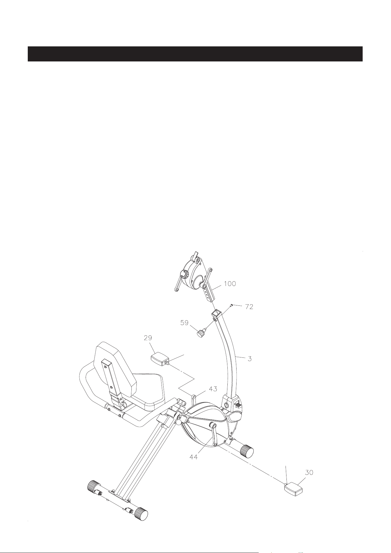
STEP 8
NOTE: The RIGHT PEDAL(30) has an R stamped on the end of the pedal shaft. The RIGHT PEDAL(30)
has right hand threads and is tightened by turning clockwise. The LEFT PEDAL(29) has an L
stamped on the end of the pedal shaft. The LEFT PEDAL(29) has left hand threads and is tightened
by turning counterclockwise.
Thread the RIGHT PEDAL(30) to the RIGHT CRANK(44) as shown. Tighten the pedal securely. Refer to
the detail view below. The shoulder of the PEDALS(29, 30) should be in contact with the CRANKS(43, 44)
when securely tightened.
Repeat on the left side in order to attach the LEFT PEDAL(29) to the LEFT CRANK(43).
STEP 9
Install Handlebar Assembly by inserting the HANDLEBAR POST(100) into the UPRIGHT(3) and secure
with the SMALL ADJUSTMENT KNOB(59). Bolt the ROUND HEAD BOLT(M6x1x12mm)(72) into the
UPRIGHT(3) for security.
NOTE: Make sure that the pin on the SMALL ADJUSTMENT KNOB(59) is inserted into one of the holes
in the HANDLEBAR POST(100). The SMALL ADJUSTMENT KNOB(59) should be screwed in
tight to make the HANDLEBAR POST(100) t securely in the UPRIGHT(3).
Shoulder
Shoulder
Loading ...
Loading ...
Loading ...