Loading ...
Loading ...
Loading ...
ASSEMBLY INSTRUCTIONS
10
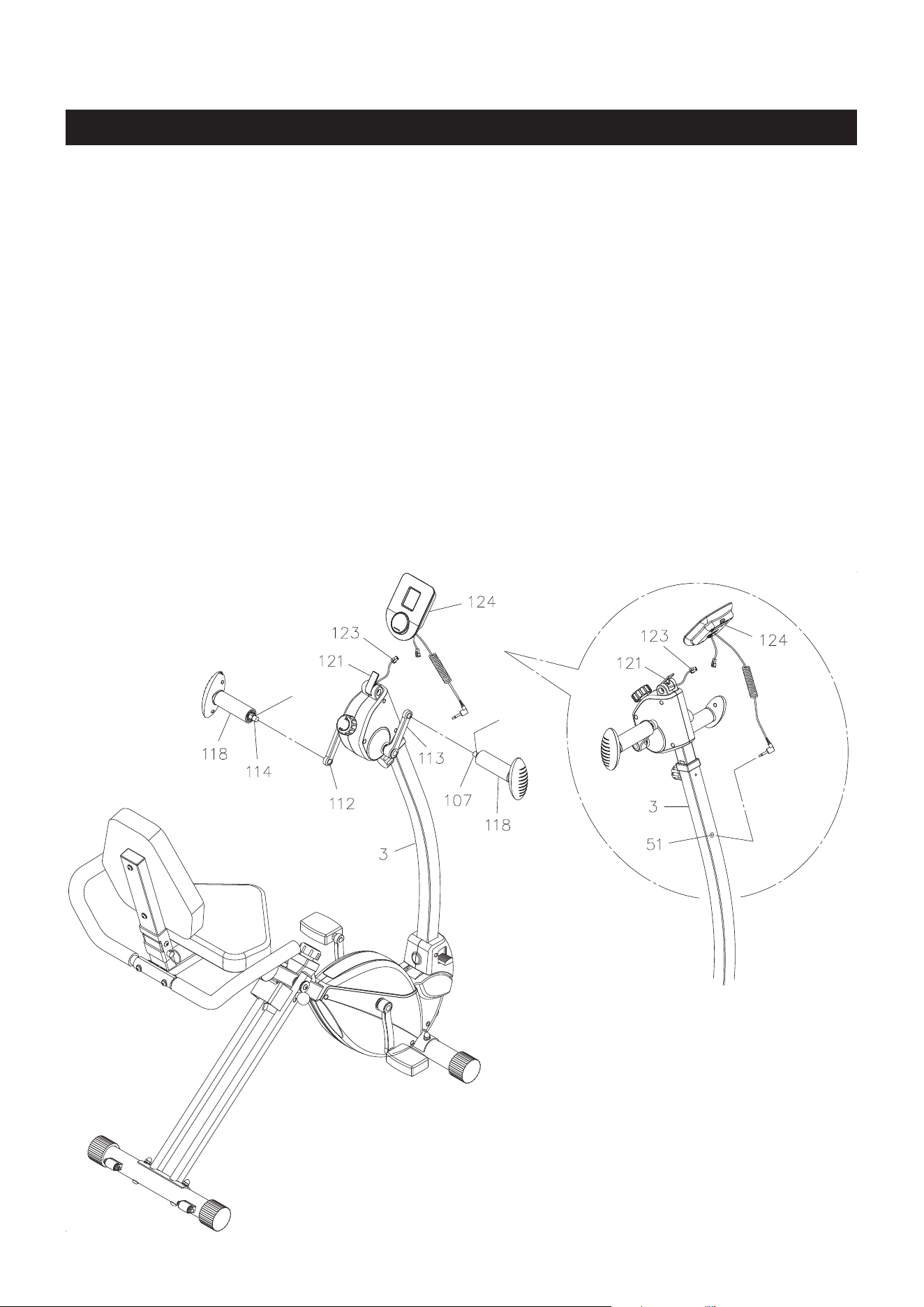
STEP 10
NOTE: The RIGHT HANDLEBAR SHAFT(107) has an R stamped on the end of the handlebar shaft. The
RIGHT HANDLEBAR SHAFT(107) has right hand threads and is tightened by turning clockwise.
The LEFT HANDLEBAR SHAFT(114) has an L stamped on the end of the pedal shaft. The LEFT
HANDLEBAR SHAFT(114) has left hand threads and is tightened by turning counterclockwise.
Attach the HANDLEBAR(118) to the right side by threading the RIGHT HANDLEBAR SHAFT(107) to the
RIGHT HANDLEBAR CRANK(113) and tighten securely. The shoulder of the HANDLEBAR SHAFTS(107,
114) should be in contact with the HANDLEBAR CRANKS(112, 113) when securely tightened.
Repeat on the left side in order to attach the other HANDLEBAR(118) to the LEFT HANDLEBAR CRANK
(112).
STEP 11
Install two AAA batteries into the METER(124), the batteries are not included. See page 12 for detailed
battery installation instructions. Insert the METER(124) onto the METER PLATE(121). Refer to the detail
view. Connect the UPPER SENSOR WIRE(123) to the short connecting wire of the METER(124). Plug the
Coil Connection Wire of the METER(124) into the socket of the SENSOR WIRE(51) which located at the
front of the UPRIGHT(3).
Shoulder
Shoulder
Loading ...
Loading ...
Loading ...