Loading ...
Loading ...
Loading ...
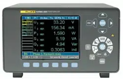
Design and Functions
Operating Controls and Display 3
3-5
Table 3-3 is an explanation of the status symbols.
Table 3-3. Status Symbols
Status Description
M Memory record active
T Wait for Trigger start condition (memory)
R Measurement active (Run mode)
H Measurement stopped (Hold mode)
Integration of selected values active
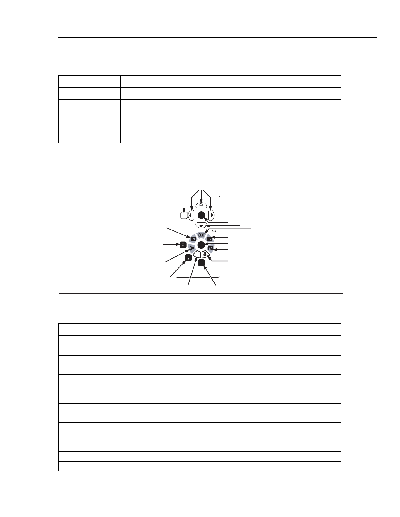
Navigation and Measuring Keys
Figure 3-3 illustrates the navigation and measuring keys on the Power Analyzer. Table 3-
4 is a list of the descriptions for the navigation and measuring keys.
MEM
ENTERESC
1...n
WAV
HOLD
RUN
26 27
14
19
15
17
27
16
18
20
21
22
23
24
25
esn007.eps
Figure 3-3. Navigation
Table 3-4. Navigation Control Descriptions
Item Description
14 Enter: confirm; call up menu
15 Numerical display
16 Recorder
17 Hold/Run: start and stop measurement
18 Oscilloscope diagrams
19 Print
20 Show power, current, voltage
21 Save
22 Select channel
23 Vector display
24 Show totals of all channels
25 Frequency analysis
26 Esc: cancel, up one menu level
27 Cursor keys: up, down, left, and right
1.888.610.7664 sales@GlobalTestSupply.com
Fluke-Direct.com
Loading ...
Loading ...
Loading ...