Loading ...
Loading ...
Loading ...
11
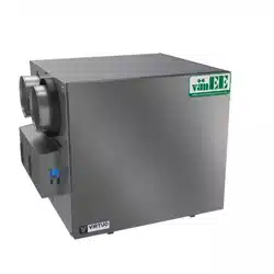
3. CONNECTIONS
3.1 elecTricAl connecTion To opTionAl mAin wAll conTrol
Use the terminal connector included to perform the electrical connection for optional main wall control. Check if all wires are
correctly inserted in their corresponding holes in the terminal connector. Use screws to x wires in the terminal connector.
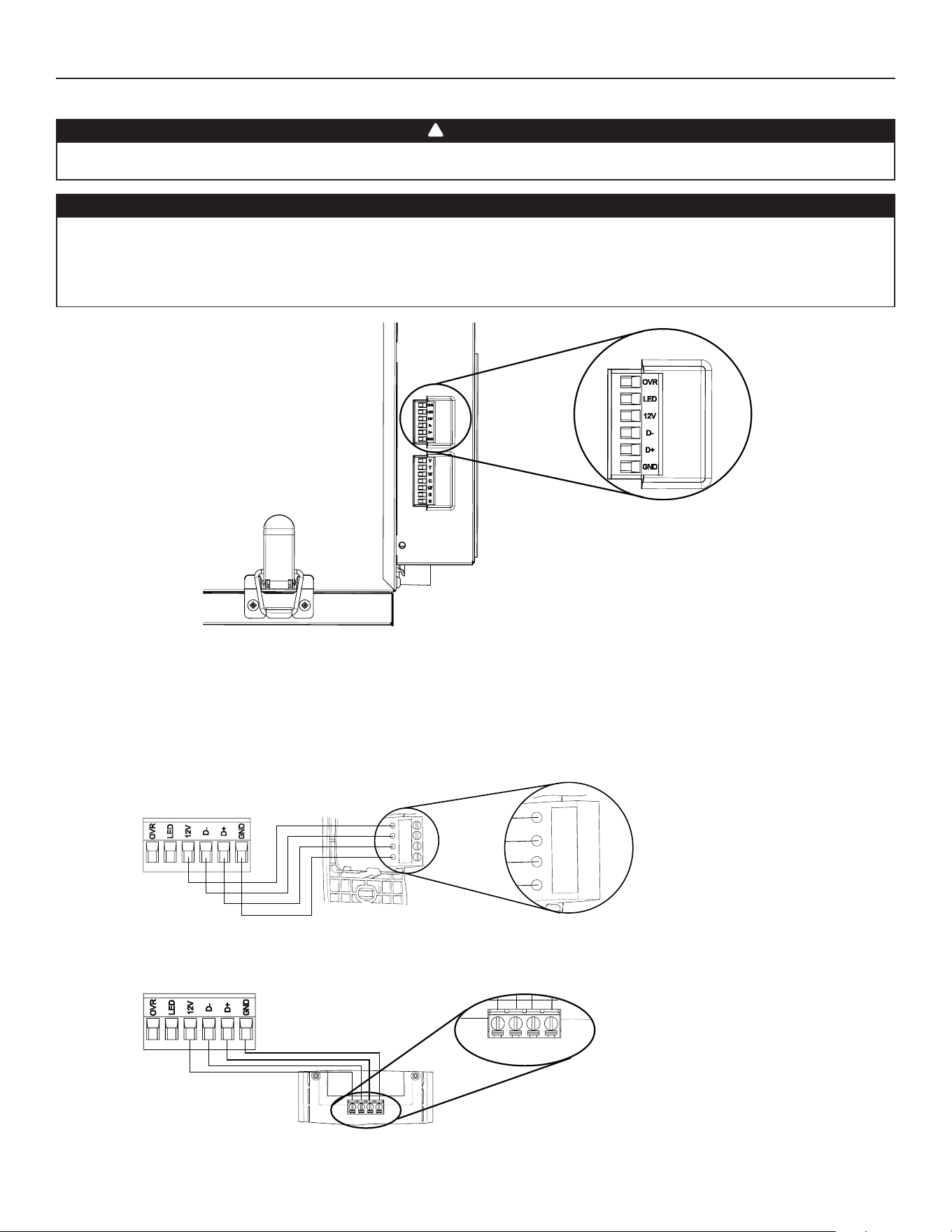
3.1.1 elecTricAl connecTion To deHumidisTAT or AuTomATic opTionAl mAin wAll conTrol
Gnd
D+
12V
D-
VC0241
12V
D-
D+
Gnd
Once the wall control connections have been made, insert the terminal connector in the electrical compartment.
NOTE : For information about the operation of the wall control, refer to the corresponding Installation and User Guide, available at
vanee.ca or venmar.ca.
Always disconnect the unit before making any connections. Failure to cut power could result in electrical shock
or damage to the wall control or electronic module inside the unit.
Never install more than one optional main wall control per unit. Make sure that the wires do not short-circuit
between themselves or by touching any other components on the wall control. Avoid poor wiring connections.
To reduce the risk of electrical interference (noise), do not run wall control wiring next to control contactors or
near light dimming circuits, electrical motors, dwelling/building power or lighting wiring or power distribution
panel.
CAUTION
WARNING
!
HD0491
uniT boTTom view
TerminAl connecTor
3.1.2 elecTricAl connecTion To AdvAnced opTionAl mAin wAll conTrol
12V D- D+ Gnd
VC0242
12V D- D+ Gnd
Loading ...
Loading ...
Loading ...