Loading ...
Loading ...
Loading ...
I
J
SCALE 0.125
A
B
C
SCALE 0.125
SCALE 0.125
MOTOR
ON
LEFT
SCALE 0.125
3
E
E(0.125)
3
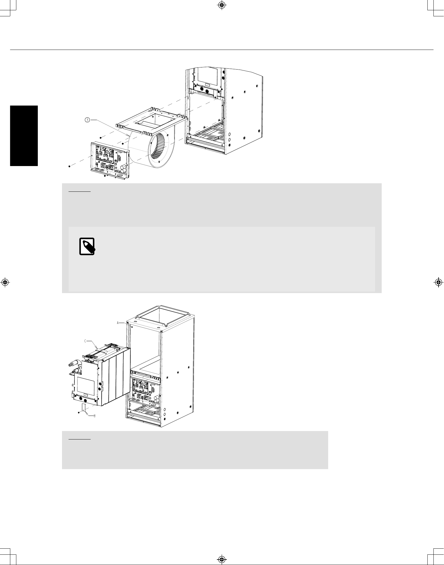
③ Motor on left
Step. 7 Reinsert the blower assembly with the motor now on the left into the air handler cabinet and
reuse the (2) screws that secured the fan assembly in position. Reroute the connector for the motor
back into the enclosure and reconnect. Reinstall Control Box.
NOTE
The wiring harness might have to be removed from the plastic retainers mounted to
the motor bracket in order to have sufficient length to reach the electrical enclosure
mounted to the fan assembly. Ensure wiring harness is secure so it cannot be pulled
into the fan.
Step. 8
A. Disconnect the waterproof thermistor harness inside the coil portion of the cabinet.
B. Remove the brackets which secure the coil assembly.
C. Slide the coil assembly out of the air handler cabinet.
SVZ-KP12,18, 24, 30, 36NA
© 2022 Mitsubishi Electric US, Inc. 26 Specifications are subject to change without notice.
ENGLISH
Loading ...
Loading ...
Loading ...