Loading ...
Loading ...
Loading ...
NORMA 4000/5000
Operators Manual
10-4
Apparent power
RMSRMS
IUS ⋅=
Reactive power
[4]
22
PSQ −= (+…inductive, -…capacitive)
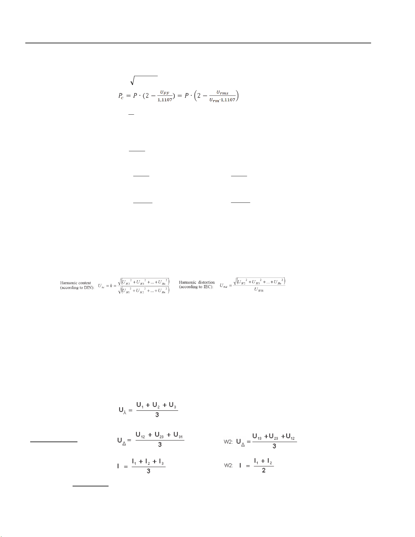
Corrected Power
[5]
(Standard EN60076-1)
Power factor
S
P
=λ
Phase shift
[6]
λ
=
ϕ
arccos
Impedance
2
RMS
I
S
Z =
Serial components
2
RMS
S
I
P
R =
2
RMS
S
I
Q
X =
Parallel components
P
U
R
2
RMS
P
=
Q
U
X
2
RMS
P
=
Energy by the integration
function for P (separately
for positive and negative P)
⋅⋅= dtiuE
Notes
[1]
Mean value of pure (AC) sine = 0.
[2] For crest factor calculation the greater absolute value of positive and negative peak is taken.
[3] The standard method to calculate THD and HC is defined by the sum of the single harmonics. These individual values are not
commonly available in the NORMA Power Analyzer. The method used here (replacement by calculation from fundamental and
RMS) adds a deviation in the case of interharmonics only.
[4] Due to distortion (harmonics) and varying load, reactive power Q originates not only from phase shift. The sign of Q is taken from
the phase shift test which could fail if no unambiguous phase shift between voltage and current is detectable.
[5] For W3 system the user may opt to use voltage rms and rm from the phase voltage or the phase-to-phase voltage depending on
the type of transformer. W2 system calculation is fixed to the phase-to-phase voltages (due to phase voltage not being available).
In a N5000 instrument, if W2 system and phase voltage method is selected, P
c
is only available for the second system
(P
C4
/P
C5
/P
C6
/P’
C
).
[6] See also [3]. The phase shift ϕ for broad-band signals is in fact an artificial result, it conforms to a physical angle for sinusoidal
signals only. Often it makes sense to use ϕ
H01
, the phase shift of the fundamental voltage to the fundamental current, instead.
Total values (sum or average)
Some values may be unavailable for instruments equipped with 1, 2, 4, or 5 channels. The selection of
system W2 is for channels 1-2 only (channel 3 can be used independently). Channels 4-5-6 of a NORMA
5000 are always configured as system W3.
Average value of the phase
voltages
(RMS, RM, M, RMC, H01)
unavailable with W2
W2: na
Average value of the
ph-to-ph voltages
(RMS, RM, M, RMC, H01)
Average value of the phase
currents
(RMS, RM, M, H01)
Totals (sum) of power values
1.888.610.7664 sales@GlobalTestSupply.com
Fluke-Direct.com
Loading ...
Loading ...
Loading ...