
BTRP230V(50) THERMOSTAT - FULL USER MANUAL


TABLE OF CONTENTS
1. Introduction ...............................................................................................................................................................4
1.1 Product Compliance ......................................................................................................................................................................4
1.2 Safety Informations .......................................................................................................................................................................4
1.3 Product Overview ..........................................................................................................................................................................5
2. Montage ....................................................................................................................................................................6
2.1 Package content ............................................................................................................................................................................6
2.2 Proper thermostat location ...........................................................................................................................................................6
2.3 Connection description ..................................................................................................................................................................7
I A - 4 wire installation with KL08NSB wiring centre .............................................................................................................8
I B - 4 wire installation with KL06 wiring centre .................................................................................................................10
II - 3 wire installation with KL08NSB wiring centre ............................................................................................................12
III A - work with RM-16A relay module - volt-free heating source control ..........................................................................14
III B - work with RM-16A relay module - connection to a solid fuel boiler controller ..........................................................14
III C - work with RM-16A relay module - connecting an electrical device with a higher power ..........................................15
3. Before you start (rst power up) ................................................................................................................................16
3.1 LCD icon description ....................................................................................................................................................................16
3.2 Button description .......................................................................................................................................................................16
3.3 First power up sequence ..............................................................................................................................................................17
4. Work modes ..............................................................................................................................................................18
5. User settings (basic settings) .....................................................................................................................................19
5.1 Schedule mode - programming schedule ....................................................................................................................................19
5.2 Time/Date ...................................................................................................................................................................................22
5.3 Thermostat calibration ................................................................................................................................................................23
5.4 Heat/cool mode change ..............................................................................................................................................................24
6. Installer parameters .................................................................................................................................................25
7. Factory Reset ............................................................................................................................................................27
8. Error codes ...............................................................................................................................................................28
9. Cleaning and Maintenance ........................................................................................................................................29
10. Technical Informations ............................................................................................................................................29
11. Warranty ................................................................................................................................................................30

4
This product complies with the essential requirements and other relevant provisions of Directives 2014/53/EU and 2011/65/EU. The full text of the EU
Declaration of Conformity is available at the following internet address: www.saluslegal.com.
• Before starting installation work and before using the product, read the entire manual.
• The information contained in the instructions is essential for proper functioning.
• To avoid accidents resulting in personal injury and material damage, please follow all safety precautions, specied in this manual.
• The device should not be used by people with limited mental, sensory or mental abilities, without experience, of insucient knowledge as well as
children.
• Do not use an unassembled device (eg without a cover).
• The device may only be opened by a qualied person.
• Keep electrical devices out of the reach of children and ensure that they do not play with it. Children should not be left unattended. If necessary,
disconnect the control system for the entire room.
• Do not leave the packaging, cabinet, or any loose parts of the device unattended, as they pose a risk to children.
WARNING!
• Installation must be carried out by a qualied person with appropriate electrical qualications in accordance with standards and regulations in force in
the given country and in the EU.
• Never try to connect the device other than as described in the manual.
• Before assembly, repair or maintenance as well as during any connection works it is absolutely necessary disconnect the mains supply and make sure
that the terminals and electric wires are not live.
• The device may not be exposed to extreme temperatures, strong vibrations or subjected to mechanical shock.
• The device should not be used in unfavorable environmental conditions or in rooms where there is a concentration of ammable gases, fumes or dust.
WARNING!
• There may be additional protection requirements for the entire installation that the installer is responsible for maintaining.
1. Introduction
1.1 Product Compliance
1.2 Safety Informations
Care for the natural environment is of paramount importance to us. The awareness that we manufacture electronic devices obliges us
to dispose of used electronic components and devices safely. Therefore the company has received a registration number issued by the
Chief Inspector for Environmental Protection. The crossed out symbol the trash can on the product means that the product must not be
disposed of with ordinary waste containers. Sorting waste for recycling helps to protect the environment. It is the user’s responsibility
to surrender used equipment to a designated collection point for recycling waste from electrical and electronic equipment.

5
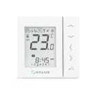
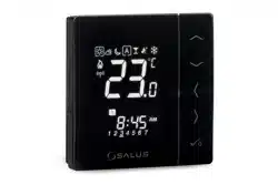
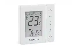
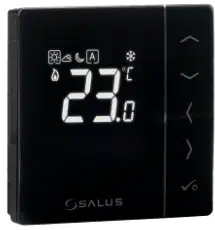
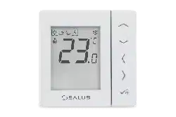
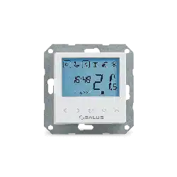
The BTRP230V(50) from SALUS Controls is a stylish and accurate 5/2 or 24h programmable electronic thermostat with a large, easy to read Liquid Crystal
Display (LCD). It is ush-mounted (in a 55 mm frame) temperature controller dedicated for surface heating / cooling, characterized by high thermal
inertia. It is connected to the wired wiring centre KL08NSB. Thermostat has the function of creating your own schedules. It can control group (SLAVE)
thermostats - via wiring centre it sends them an NSB (nighttime temperature reduction) signal and switches them to economic temperature. The time
schedule is common to all thermostats (according to weekly (MASTER) thermostat), but temperatures are set individually on each thermostat.
The programmable room thermostat BTRP230V(50) is both a programmer and a room thermostat. A programmer allows you to set ‘ON’ and ‘OFF’ time
periods to suit your own lifestyle. A room thermostat works by sensing the air temperature, switching on the heating when the air temperature falls below
the thermostat setting and switching it o once this set temperature has been reached.
So, a programmable room thermostat lets you choose what times you want the heating to be on, and what temperature it should reach while it is on.
It will allow you to select dierent temperatures in your home at dierent times of the day (and days of the week) to meet your particular needs.
Turning a programmable room thermostat to a higher setting will not make the room heat up any faster. How quickly the room heats up depends on the
design of the heating system, for example, the size of boiler. Neither does the setting aect how quickly the room cools down. Turning a programmable
room thermostat to a lower setting will result in the room being controlled at a lower temperature, and saves energy.
The way to set and use your programmable room thermostat is to nd the lowest temperature settings that you are comfortable with at the dierent
times you have chosen, and then leave it alone to do its job. The best way to do this is to set low temperatures rst, say 18°C, and then turn them up by one
degree each day until you are comfortable with the temperatures. You won’t have to adjust the thermostat further. Any adjustments above these settings
will waste energy and cost you more money.
PRODUCT ADVANTAGES:
• absolutely silent operation (TRIAC)
• has a PWM control algorithm
• protection against too high or too low temperature using an additional FS300 oor sensor
• protection of thermostatic valves against stagnation (VP)
• an input for the additional temperature sensor
• has frost protection mode
• mounting in a φ 60 mm wall box
1.3 Product Overview
6
2. Montage
2.1 Package content
1) BTRP230V(50) thermostat
2) Short instruction
3) Mounting screws
2.2 Proper thermostat location
Please note:
Wall mounting
Mounting: to mount thermostat you can use accesories included with the set (mounting screws). Remove back housing to mount it to the wall box. After
attachement put together front and back housing.
The ideal position to thermostat mounting is about 1,5m under oor level far from heating or cooling sources.
Thermostat can’t be exposed to sunlight or any extreme conditions like for example draft.
Because of re and explosion risk there is not allowed to use thermostat in atmosphere of explosive gases and ammable liquids (eg coal dust). In case
if any of listed dangers occur you have to use additional protection measures – anti-dust and explosive gases (tight cover) or prevent their formation.
Furthermore, thermostat can’t be used in condensation of water vapor conditions and be exposed to water action.
1
2
3
5
6
1 2
3
4
Make sure that wires are not connected to 230V. Then connect the
thermostat. Please refer to 2.3 chapter - Connection Description.
Mount the thermostat like in the pictures above
(use designed holes for screws).
Install the decorative frame and then slide the front of the thermostat
onto its back. The thermostat is ready to work. You can set the desired
temperature with the buttons.
7
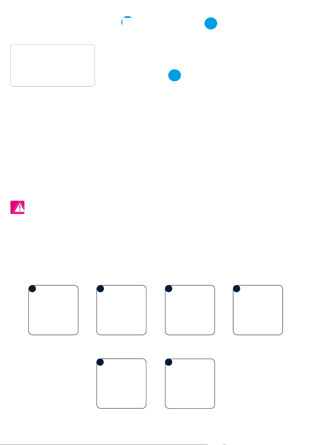
L, N - power supply 230V
- NSB - Night temperature reduction
(230V output)
- SL - 230 V AC output signal
CO - Switching jumper between heating and
cooling (input 230V AC)
S1, N - additional temperature sensor
eg. FS300
2.3 Connection description
Wejście NSB
w regulatorze SLAVE
BTRP 230 KL08 NSB
L
S1
N
N
CO
L
SL
N
BTRP 230
Wyjście NSB
L
N
S1
N
CO
L
AC 230V
N
T30NC
/
NSB input in
SLAVE thermostat
NSB output
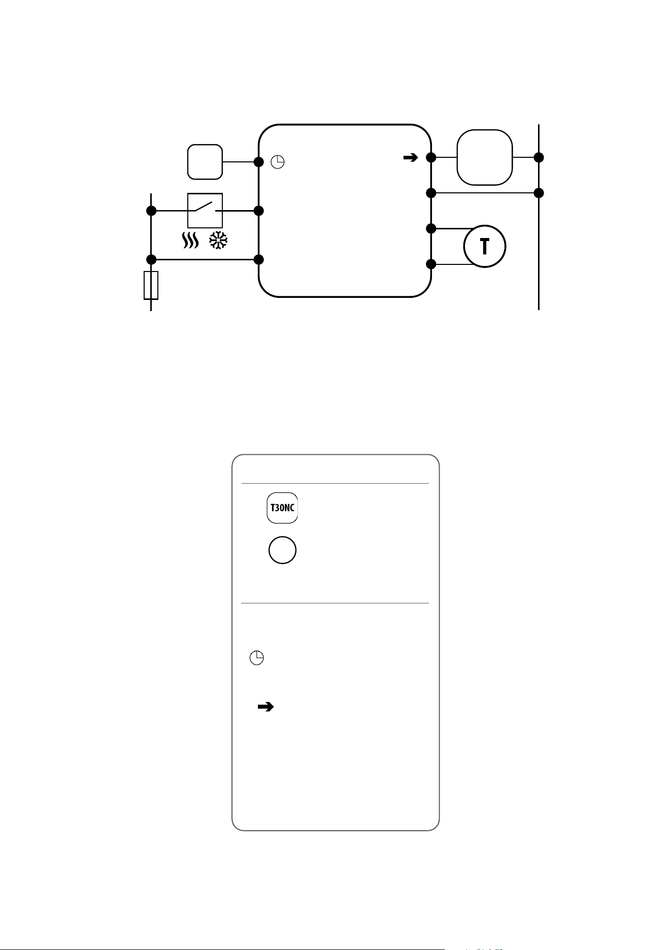
Legend:
Thermal actuator
Temperature sensor
Symbols explanation:
T
8
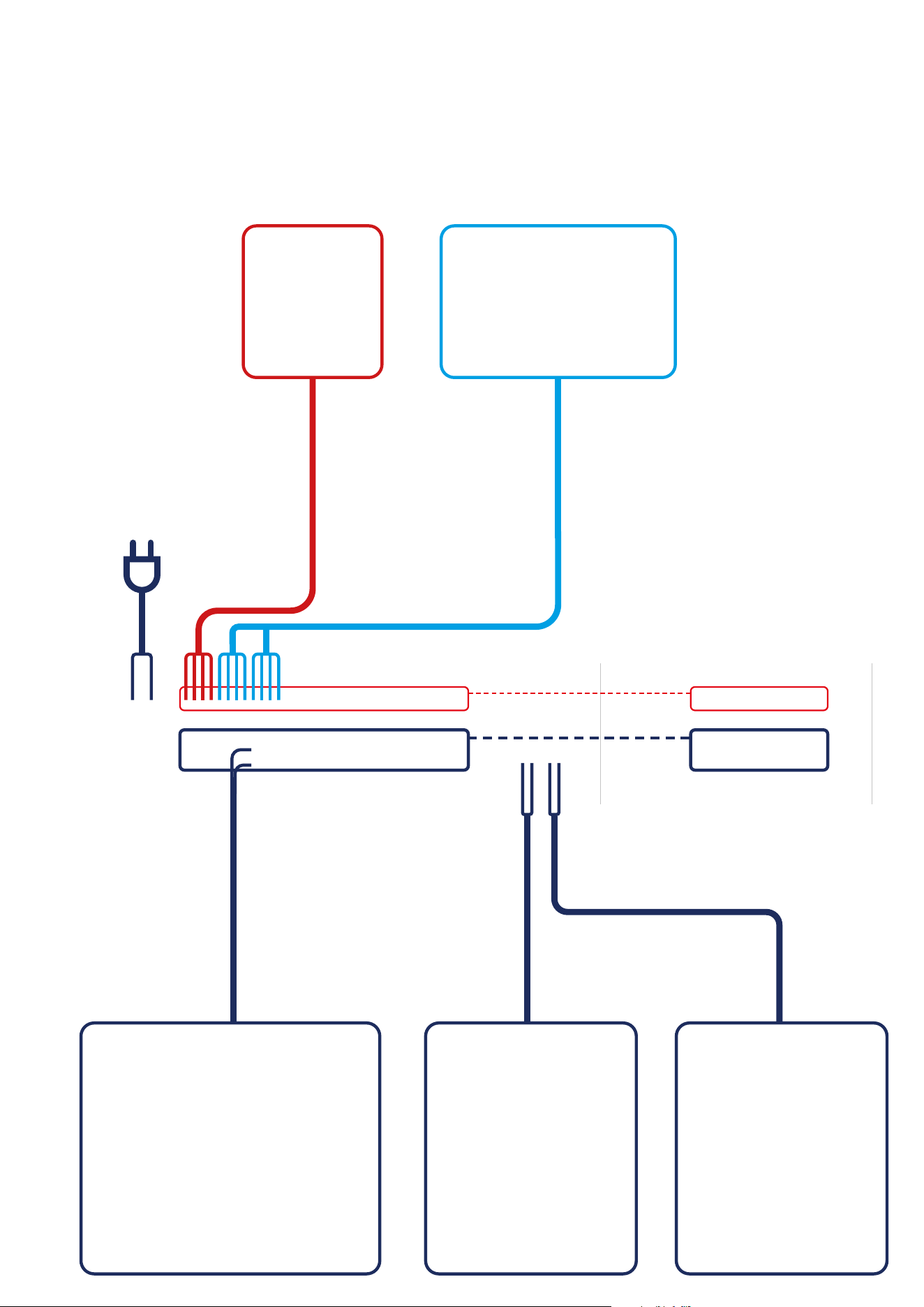
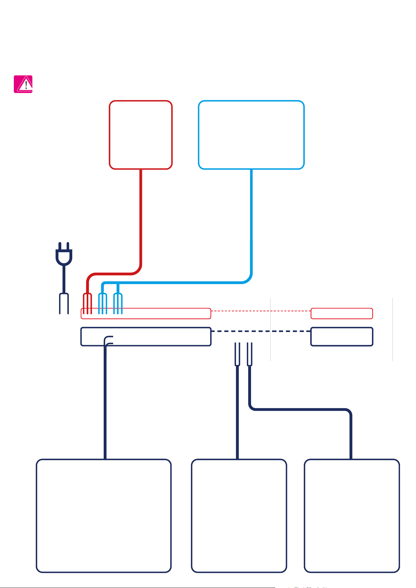
THB23030 PUMP (optional)T30NC230 BOILER
4 wires x 0.75 mm2
4 wires x 0.75 mm2
Power Supply
230V AC
Actuators wires
2 x 0.75 mm2
Pump control wires
2 x 1 mm2
Boiler control wires
2 x 1 mm2
KL08NSB KL04NSB (optional)
SLAVEMASTER
BTRP230(50) BTR230(20)BTR230(20)
I A - 4 wire installation with KL08NSB wiring centre
When BTRP230V(50) thermostat works as a MASTER (group controller) it means it takes control of SLAVE thermostats e.g. BTR230V(20). MASTER
thermostat controls SLAVE thermostat only when SLAVE thermostat is in AUTO mode. Comfort (SUN) and economy (MOON) setpoint temperatures are set
individually on each thermostat but switching between those temperature is based on time schedule taken from BTRP230(50) thermostat which works
like a group controller. Functions such as: setpoint temperature change, holiday mode, party mode or frost protection mode are not managed by MASTER
thermostat.
9
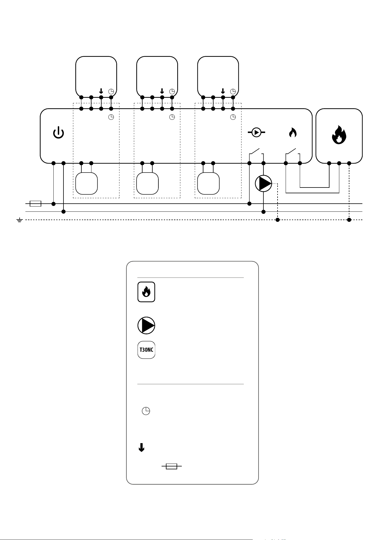
SLAVEMASTER
L
AC 230V
L
N
N
1 - 8 Strefy 1 - 8 Strefy 1 - 8 Strefy
KL08NSB
Pump BoilerPower
L N
SL
T30NC
L N
SL
T30NC
L N
SL
T30NC
lu ub
VS30 RT200 RT520
L L L
L
or
or
L
1 2
BOILER CONNECTION*
1-8 Zones1-8 Zones1-8 Zones
3 4
N N N
N N
N
L
max 6
per zone
max 6
per zone
max 6
per zone
BTRP230V(50) BTR230V(20) BTR230V(20)
L, N - power supply 230V
- NSB - Night temperature reduction
(230V output - in MASTER thermostat)
(230V input - in SLAVE thermostat)
- SL - 230 V AC actuator control signal
- fuse
Legend:
Symbols explanation:
Thermal actuator
Pump
Boiler - Boiler connection* - Boiler’s
contacts for ON/OFF thermostat
(according to the boiler’s instructions)
10
I B - 4 wire installation with KL06 wiring centre
THB23030T30NC230
Power Supply
230V AC
Actuators wires
2 x 0.75 mm2
Pump control wires
2 x 1 mm2
Boiler control wires
2 x 1 mm2
KL06 PL07 PL06
PUMP (optional) BOILER
4 wires x 0.75 mm2
4 wires x 0.75 mm2
SLAVEMASTER
BTRP230(50) BTR230(20)BTR230(20)
11
L, N - power supply 230V
- NSB - Night temperature reduction
(230V output - in MASTER thermostat)
(230V input - in SLAVE thermostat)
- SL - 230 V AC actuator control signal
NC, NO - voltage-free output
- fuse
Legend:
Symbols explanation:
Thermal actuator
Pump logic module (for KL06) connection diagram
Pump and boiler logic module (for KL06) connection diagram
Pump
Boiler - Boiler connection* - Boiler’s
contacts for ON/OFF thermostat
(according to the boiler’s instructions)
PL07
PODŁĄCZENIE KOTŁA *
L
1
2
3
4
AC 230V lub 24V
N
MAX
5 (2) A
or
BOILER CONNECTION*
NC
NO
PL06
PODŁĄCZENIE KOTŁA *
NC
NO
PL06
L N
MAX
5 (2) A
AC 230V lub 24V
or
BOILER CONNECTION*
L
AC 230V
L
N
N
1 - 6 Strefy
KL06-M
Power
L N
L N
T30NC
max 6
na strefę
RT10 // RT20
Np. Np.
L N
1 - 6 Strefy
PL06
L N
L N
T30NC
max 6
na strefę
RT520
COM NO
lub
NC
NO
PODŁĄCZENIE KOTŁA *
L
AC 230V
L
N
N
1 - 6 Strefy
KL06-M
Power
L N
L N
T30NC
max 6
na strefę
RT10 // RT20
Np. Np.
L N
1 - 6 Strefy
PL06
L N
L N
T30NC
max 6
na strefę
RT520
COM NO
lub
NC
NO
L N
MAX
5 (2) A
AC 230V lub 24V
L
AC 230V
L
N
N
1 - 6 Strefy
KL06-M
Power
L N
L N
T30NC
max 6
na strefę
RT10 // RT20
Np.
Np.
L N
1 - 6 Strefy
PL06
L N
L N
T30NC
max 6
na strefę
RT520
COM NO
lub
NC
NO
PODŁĄCZENIE KOTŁA *
L
AC 230V
L
N
N
1 - 6 Strefy
KL06-M
Power
L N
L N
T30NC
max 6
na strefę
RT10 // RT20
Np. Np.
L N
1 - 6 Strefy
PL06
L N
L N
T30NC
max 6
na strefę
RT520
COM NO
lub
NC
NO
L N
MAX
5 (2) A
AC 230V lub 24V
or
or
BOILER CONNECTION*
1-8 Zones1-8 Zones1-8 Zones
max 6
per zone
max 6
per zone
max 6
per zone
BTRP230V(50) BTR230V(20) BTR230V(20)
L L LN N N
SLAVEMASTER
12
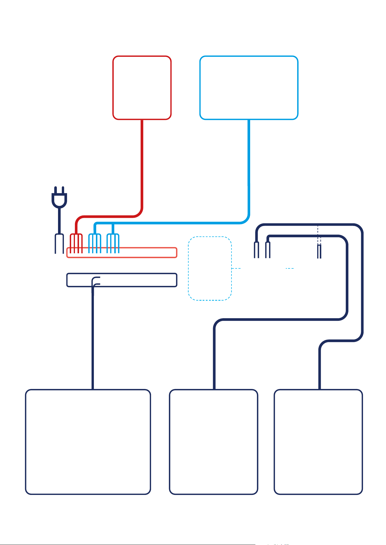
II - 3 wire installation with KL08NSB wiring centre
3 wire installation with KL08NSB wiring center. Description of the operation rules:
- BTRP230V(50) thermostat’s functionality is limited because of 3 wire installation. NSB function is disabled and BTRP230V(50) thermostat doesn’t work
as a MASTER thermostat - no eect on other thermostats like BTR230V(20)
- schedules can be set individually on each BTRP230V(50) thermostats if system is equipped with more than one BTRP230V(50) thermostat
PLEASE NOTE!
The same operating rules apply to wiring center KL06.
THB23030 PUMP (optional)T30NC230 BOILER
3 wires x 0.75 mm2
3 wires x 0.75 mm2
Power Supply
230V AC
Actuators wires
2 x 0.75 mm2
Pump control wires
2 x 1 mm2
Boiler control wires
2 x 1 mm2
KL08NSB KL04NSB (optional)
BTRP230(50) BTRP230(50) BTRP230(50)
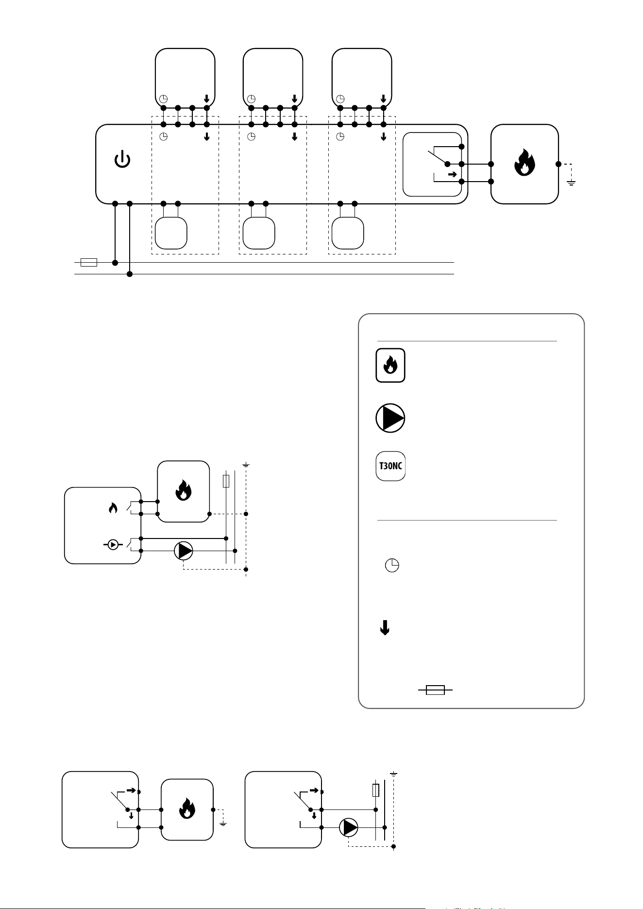
13
L
AC 230V
L
N
N
1 - 8 Strefy 1 - 8 Strefy 1 - 8 Strefy
KL08NSB
Pump BoilerPower
L N
SL
T30NC
L N
SL
T30NC
L N
SL
T30NC
lu ub
VS30 RT200 RT520
L L L
L
or
or
L
1 2
BOILER CONNECTION*
1-8 Zones1-8 Zones1-8 Zones
3 4
N N N
N N
N
L
max 6
per zone
max 6
per zone
max 6
per zone
BTRP230V(50) BTRP230V(50)
BTRP230V(50)
L, N - power supply 230V
- NSB - Night temperature reduction
(230V output)**
- SL - 230 V AC actuator control signal
- fuse
** - not used in 3 wire installation
Legend:
Symbols explanation:
Thermal actuator
Pump
Boiler - Boiler connection* - Boiler’s
contacts for ON/OFF thermostat
(according to the boiler’s instructions)
14
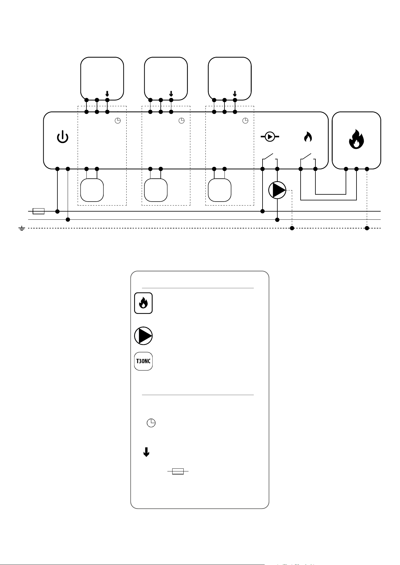
III A - work with RM-16A relay module - volt-free heating source control
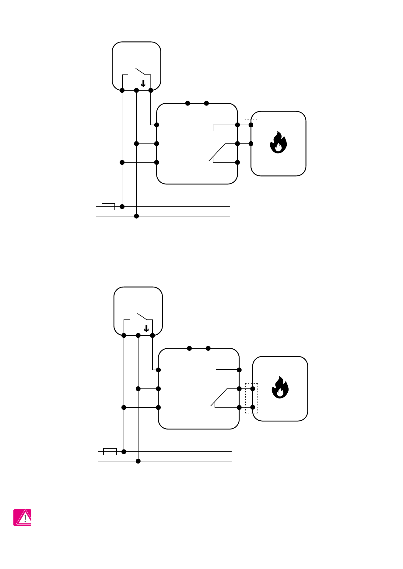
III B - work with RM-16A relay module - connection to a solid fuel boiler controller
RM-16A
L
AC 230V
N
L
AC 230V
N
L
AC 230V
N
L
AC 230V
N
NO
NO
COM
COM
(wejście)
(wejście)
(wejście)
(wejście)
NOCOM
NOCOM
NC
SL
L N SL
N
L
PODŁĄCZENIE KOTŁA *
VS30
Np.
RT520
Np.
RM-16A
MAX
16 (5) A
RM-16A
NO
NO
COM
COM
NC
SL
L N SL
N
L
VS30
Np.
NOCOM
091FL
Np.
NO
COM
NC
SL
N
L
PODŁĄCZENIE KOTŁA *
STAŁOPALNEGO
T30NC T30NC
RM-16A
NO
NO
COM
COM
NC
SL
N
L
L N
1 - 8 Strefy
KL08NSB
Power
L N
L N SL
MAX
16 (5) A
Connection of a 230 V AC voltage thermostat to a boiler
(or other device) with an ON - OFF contact.
BTRP230V(50)
BOILER CONNECTION*
(input)
PLEASE NOTE! Activate the thermostat in the solid fuel boiler controller.
RM-16A
L
AC 230V
N
L
AC 230V
N
NO
NO
COM
COM
(wejście)
NC
SL
L N SL
N
L
PODŁĄCZENIE KOTŁA *
VS30
Np.
VS30
Np.
091FL
Np.
Podłączenie regulatora napięciowego 230V AC do sterownika kotła stałopalnego
wyposażonego w styk ON - OFF.
BTRP230V(50)
(input)
BOILER CONNECTION*
Connection of a 230 V AC voltage thermostat to a solid fuel boiler controller with
an ON - OFF contact.
15
RM-16A
L
AC 230V
N
L
AC 230V
N
L
AC 230V
N
L
AC 230V
N
NO
NO
COM
COM
(wejście)
(wejście)
(wejście)
(wejście)
NOCOM
NOCOM
NC
SL
L N SL
N
L
PODŁĄCZENIE KOTŁA *
VS30
Np.
RT520
Np.
RM-16A
MAX
16 (5) A
RM-16A
NO
NO
COM
COM
NC
SL
L N SL
N
L
VS30
Np.
NOCOM
091FL
Np.
NO
COM
NC
SL
N
L
PODŁĄCZENIE KOTŁA *
STAŁOPALNEGO
T30NC T30NC
RM-16A
NO
NO
COM
COM
NC
SL
N
L
L N
1 - 8 Strefy
KL08NSB
Power
L N
L N SL
MAX
16 (5) A
(input)
BTRP230V(50)
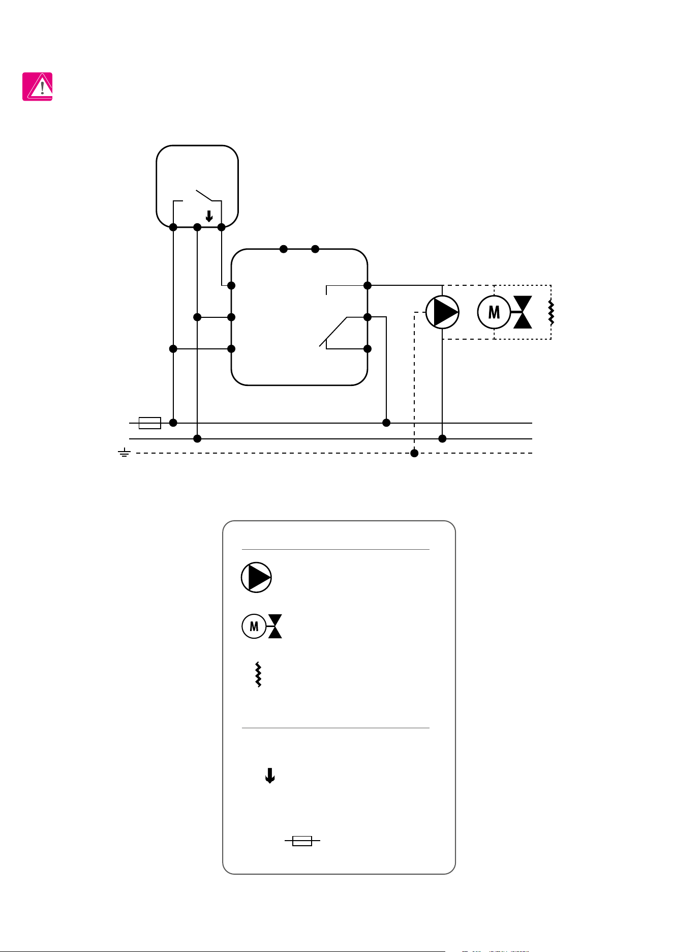
III C - work with RM-16A relay module - connecting an electrical device with a higher power than the thermostat relay allows
PLEASE NOTE! The maximum current consumption of an electrical device should not exceed 16A.
L, N - power supply 230V
- SL - 230 V AC control signal
NO, COM, NC - voltage-free output
- fuse
Legend:
Symbols explanation:
Pump
Valve actuator
Heating mat
16
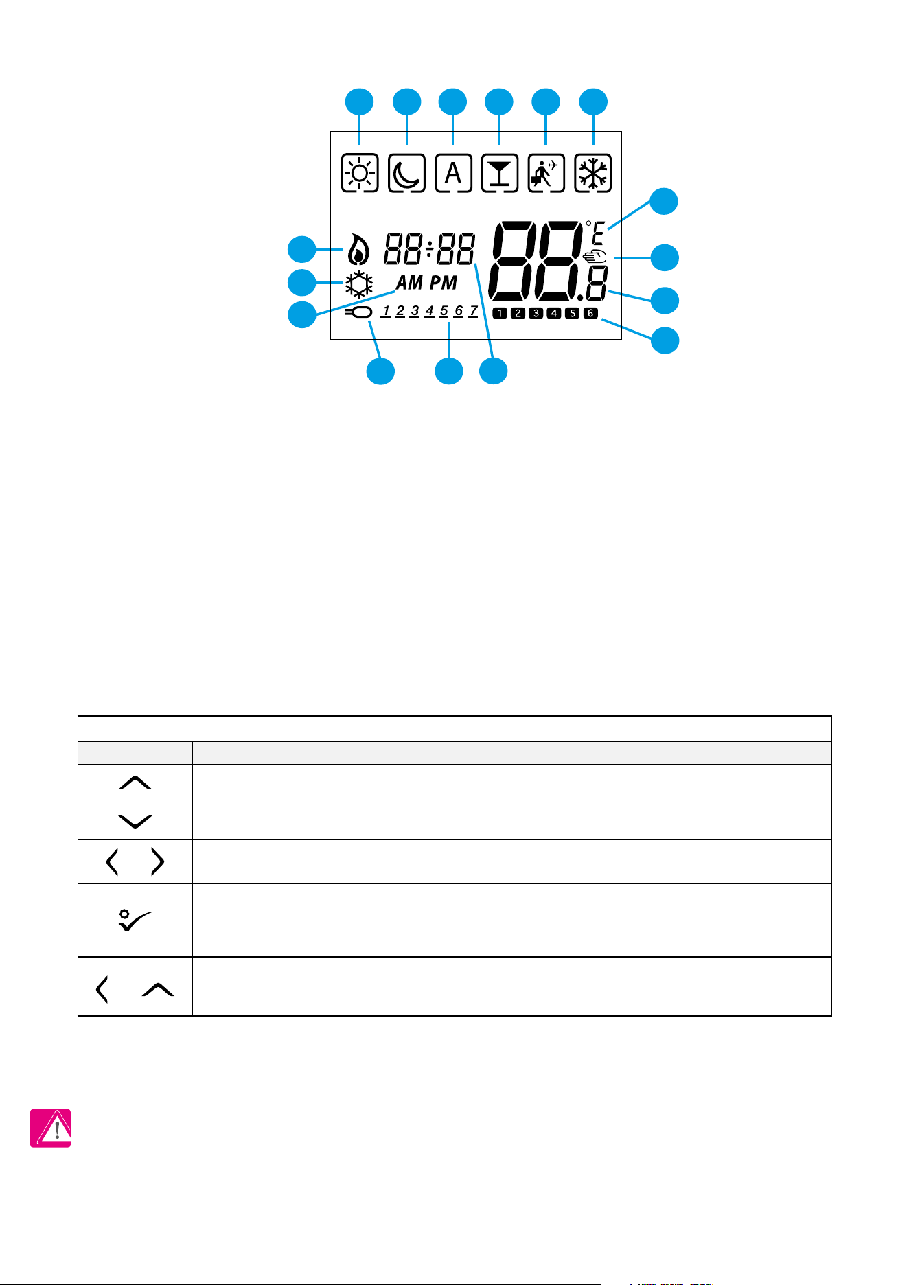
3. Before you start (rst power up)
3.2 Button description
3.1 LCD icon description
1. Comfort temperature
2. Economic temperature
3. Automatic mode
4. PARTY mode
5. Holiday mode
6. Frost protection mode
7. Temperature unit
8. Manual mode / override temp.
9. Current / set temperature
10. Program number
11. Clock
12. Day indicator
13. External temperature sensor
14. AM / PM
15. Cooling mode ON
16. Heating mode ON
16
15
11
12
13
14
7
8
9
10
1 2 3 4 5 6
PLEASE NOTE! The LCD screen can be activated by using any button.
OR
1. Increase or decrease setpoint temperature.
2. Increase or decrease Day, Clock, Timer, Party and Holiday.
3. Select installer parameter value.
1. Mode selection.
2. Moving between parameters.
1. OK key: Short press to conrm selection.
2. Long press to save and exit.
3. When Main Screen – long press to enter the user settings.
+
Hold down these buttons for 3 SECONDS to enter installer parameter settings.
Button
Function
Button Description
OR
17
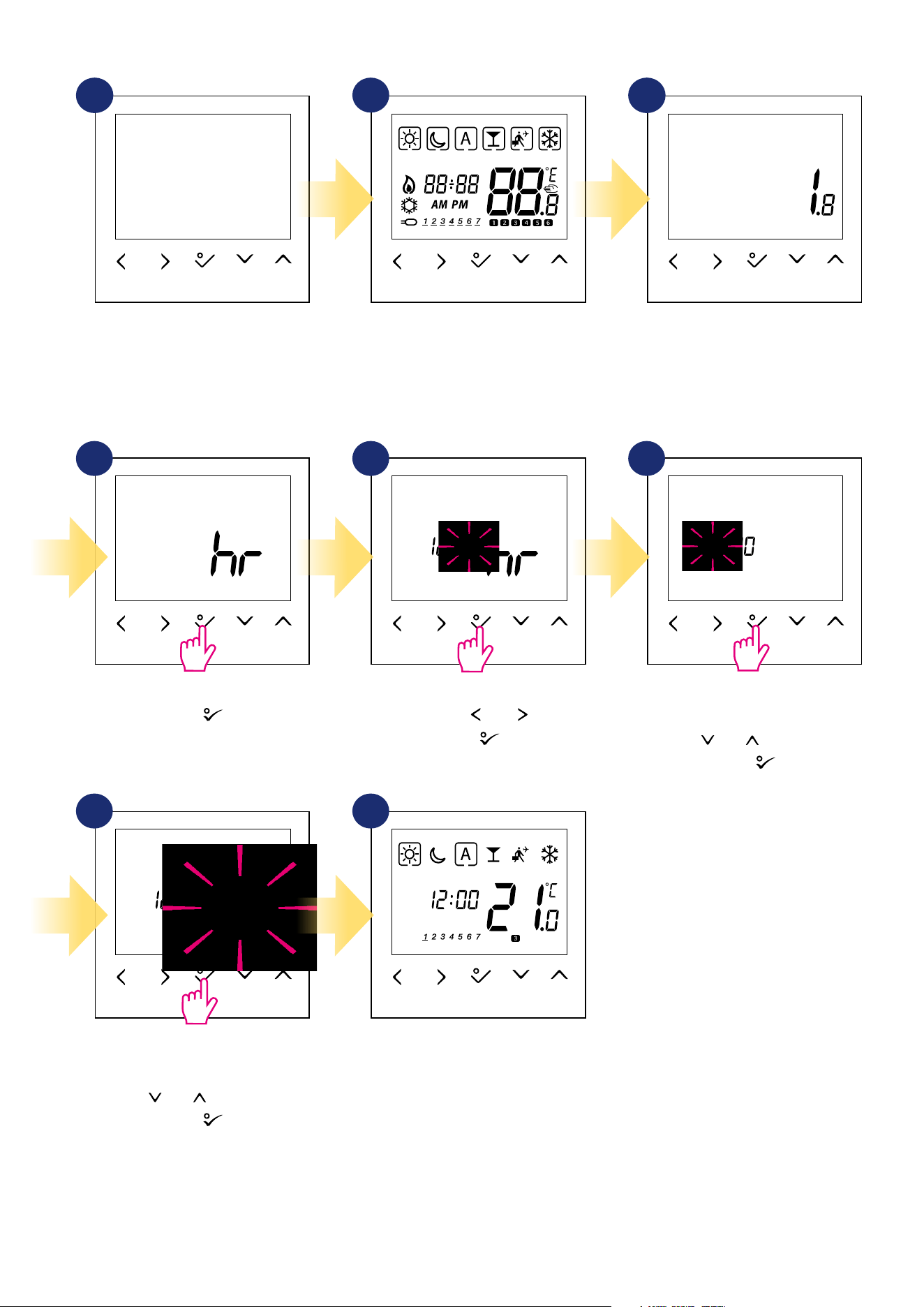
3.3 First power up sequence
...display will show all icons...
Conrm by button.
Set date (year, month and day) using
„ ” or „ ” buttons.
Conrm by button.
After all, the main screen will be
displayed.
Set time format „ ” or „ ” buttons.
Conrm by button.
Set time (hours and minutes) using
„ ” or „ ” buttons.
Conrm by button.
...then thermostat will display the
software version.
To power on the thermostat you
have to connect it to the 230V
power supply then...
2
1
4 5 6
3
7 8
18
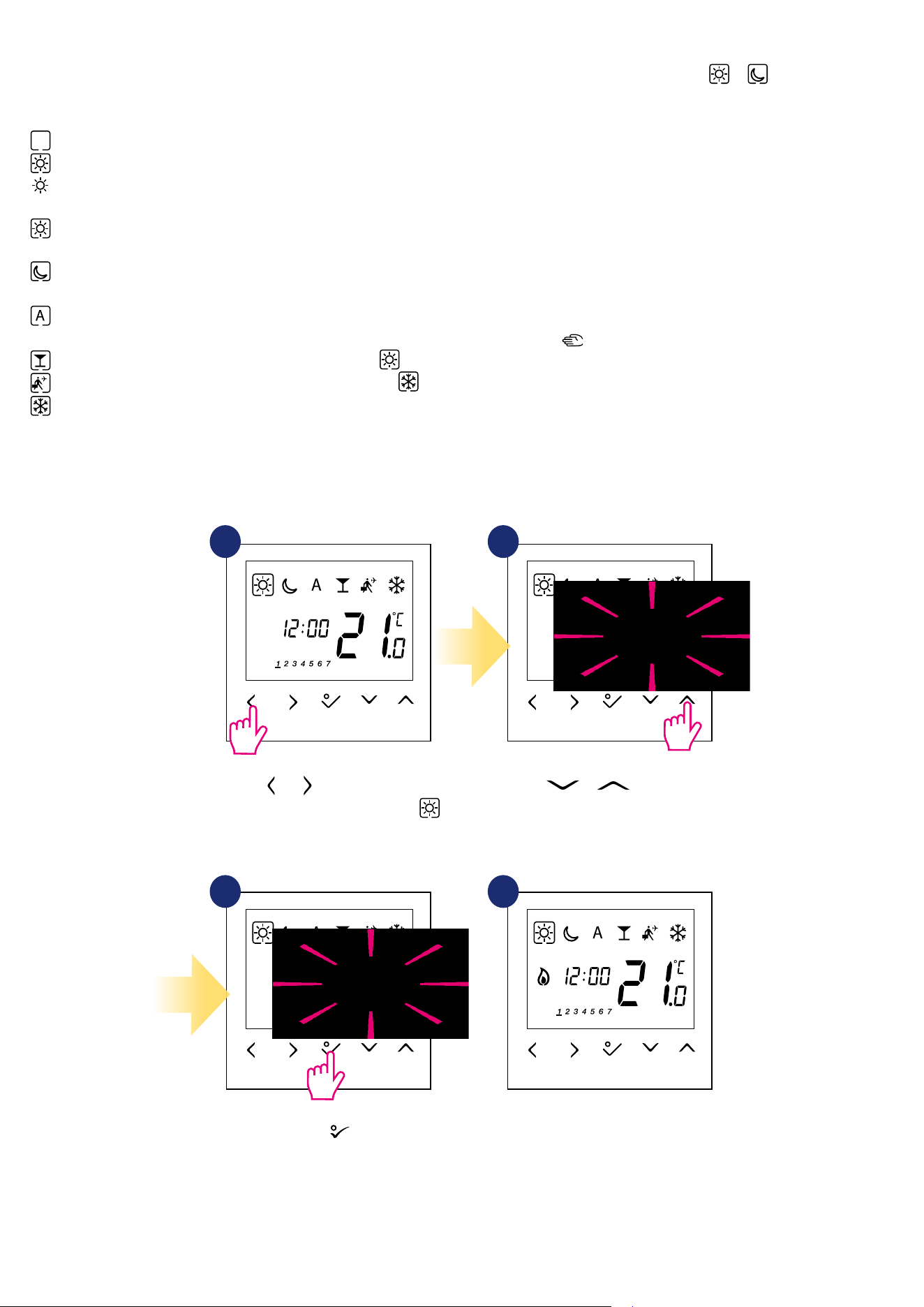
4. Work modes
Use or buttons to switch
between work modes. Choose
in this case.
1 2
43
Use or buttons set
temperature setpoint.
Conrm by button.
Thermostat will go back to the main
screen after saving the settings.
BTRP230V(50) oers a few work modes. Frame on a given icon indicates which mode is currently active. In manual mode or only one temperature
level is maintained. Thermostat follows programmed schedule when AUTO mode is active („A” icon). Detailed description of work modes is located below:
- Frame - means that the work mode is active (the icon of the work mode must be in the center of the frame). For example:
- means that comfort temperature mode is active
- means that comfort temperature mode is inactive
Example - comfort temperature mode setpoint editing:
- Comfort temperature mode - pre-dened setpoint temperature. Usually set when we are indoors. The highest maintained temperature in
heating mode or the lowest if thermostat works in the cooling system. Acting alone works as a manual mode. Temperature range: from 5°C to 35°C.
- Economic temperature mode - pre-dened setpoint temperature. Usually set at night or when we are out of the house. Acting alone works as a
manual mode. Temperature range: from 5°C to 35°C.
- Automatic mode temperature (schedule) - follows programmed schedule. Schedule can be temporarily override with new setpoint
temperature (temporary override mode will be active to the next change forced by schedule, hand icon will be displayed).
- Party mode - this mode sets the comfort temperature for a user-dened time (maximum 9 hours 50 minutes).
- Holiday mode - this mode sets the frost protection mode for a user-dened time (maximum 99 days).
- Frost protection mode - usually used during extended periods of absence or during the holidays (only available in heating mode). Temperature
range: from 5°C to 17°C.
3
19
5. User settings (basic settings)
5.1 Schedule mode - programming schedule
To program schedule, please follow steps below:
There are 4 possible schedule variants. Use and buttons to select schedule variant and conrm by button:
Separate schedule for WORKING DAYS. Separate schedule for WEEKENDS.
One schedule for
WHOLE WEEK
Seven separate schedules for
SINGLE DAYS
1 2
3
Enter into the schedule settings.
Hold button for 3 seconds to
enter the menu.
3 sec.
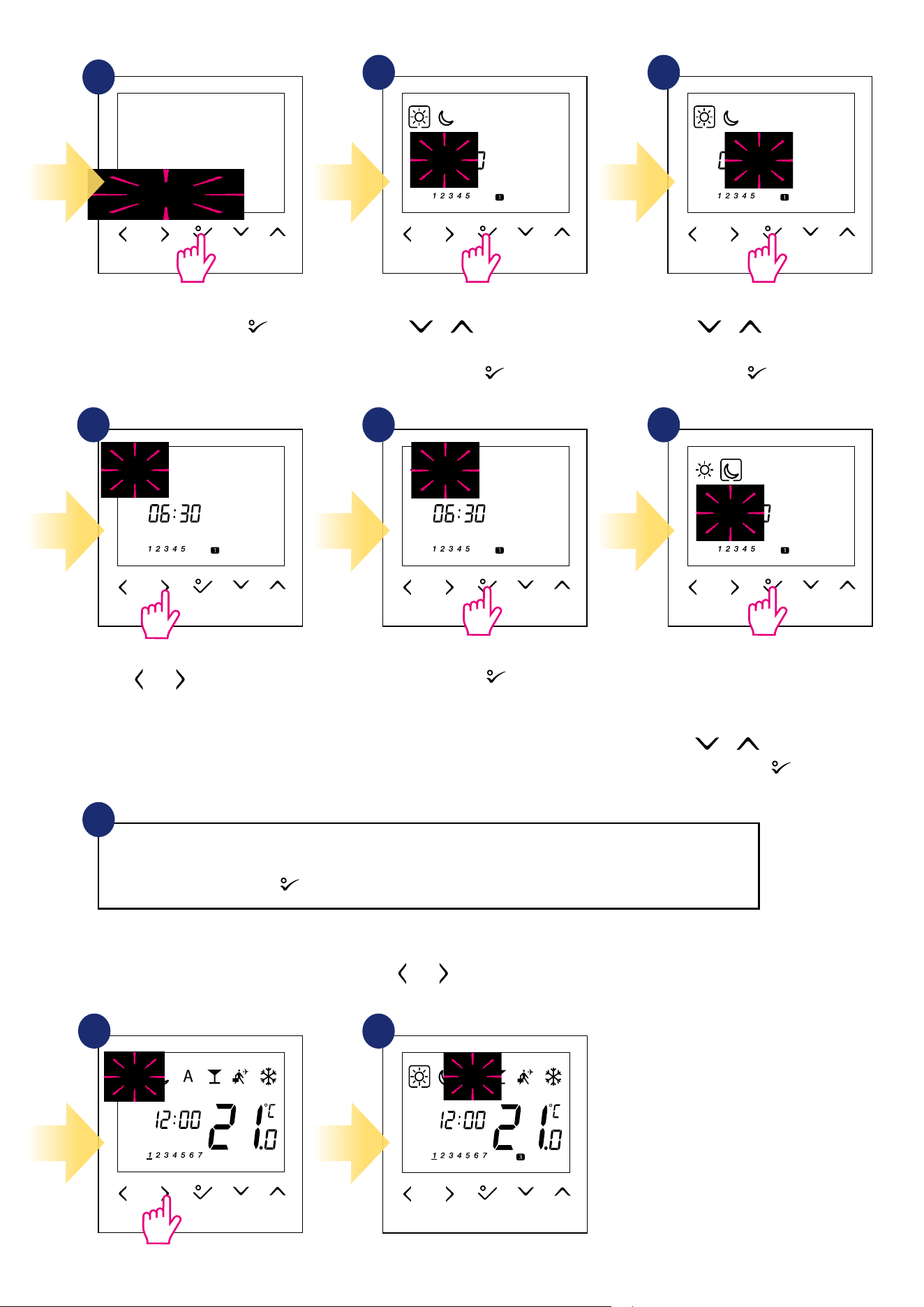
20
Select schedule variant by
button. Use or buttons to set hour
for the rst program.
Conrm by button.
Use or buttons to set mi-
nutes for the rst program. Conrm
by button.
Repeat steps 5 and 9 for the next time periods in the schedule to set whole program for selected variant. No
time --:-- on the display means given program is skipped. There are 6 programs/time periods in the schedule.
Hold button for 3 seconds to save and exit schedule editing.
To run the schedule (activate thermostat’s automatic mode), use and buttons to move the frame to the „A” icon.
Schedule programming example for the WORKING DAYS variant:
10
4
5 6
8 97
Use and buttons to choose
comfort or economic setpoint
temperature.
Schedule editing will jump to the
next program’s time setting.
Set time for selected mode using
or buttons again.
Conrm by button.
Conrm by button.
1 2
3
3
21
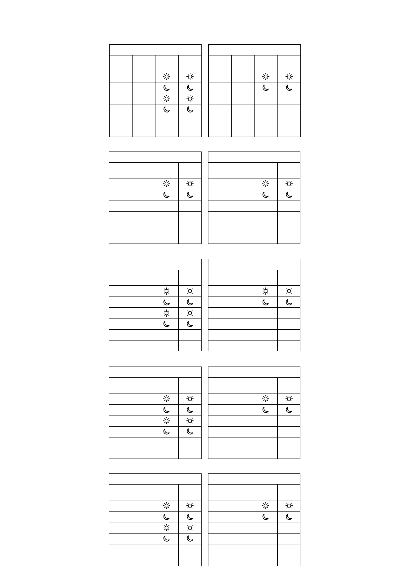
2 days (Saturday to Sunday)
Program
Program
Time
Heat set
point
Cool set
point
1 7:00
2 23:00
3 --:-- --:-- --:--
4 --:-- --:-- --:--
5 --:-- --:-- --:--
6 --:-- --:-- --:--
5 days (Monday to Friday)
Program
Program
Time
Heat set
point
Cool set
point
1 6:00
2 9:00
3 16:00
4 23:00
5 --:-- --:-- --:--
6 --:-- --:-- --:--
Program Prole 1
In addition to editing and creating your own schedule, there are also 5 default proles for built-in schedules. You can select and customize any of the
programs listed below. Default programs are selectable through Installer Parameters (parameter D17).
Program Prole 2
5 days (Monday to Friday)
Program
Program
Time
Heat set
point
Cool set
point
1 6:00
2 22:30
3 --:-- --:-- --:--
4 --:-- --:-- --:--
5 --:-- --:-- --:--
6 --:-- --:-- --:--
2 days (Saturday to Sunday)
Program
Program
Time
Heat set
point
Cool set
point
1 7:00
2 23:00
3 --:-- --:-- --:--
4 --:-- --:-- --:--
5 --:-- --:-- --:--
6 --:-- --:-- --:--
Program Prole 3
5 days (Monday to Friday)
Program
Program
Time
Heat set
point
Cool set
point
1 5:00
2 8:00
3 14:00
4 22:00
5 --:-- --:-- --:--
6 --:-- --:-- --:--
2 days (Saturday to Sunday)
Program
Program
Time
Heat set
point
Cool set
point
1 7:30
2 22:30
3 --:-- --:-- --:--
4 --:-- --:-- --:--
5 --:-- --:-- --:--
6 --:-- --:-- --:--
Program Prole 4
5 days (Monday to Friday)
Program
Program
Time
Heat set
point
Cool set
point
1 6:00
2 9:00
3 15:00
4 22:30
5 --:-- --:-- --:--
6 --:-- --:-- --:--
2 days (Saturday to Sunday)
Program
Program
Time
Heat set
point
Cool set
point
1 7:30
2 23:00
3 --:-- --:-- --:--
4 --:-- --:-- --:--
5 --:-- --:-- --:--
6 --:-- --:-- --:--
Program Prole 5
5 days (Monday to Friday)
Program
Program
Time
Heat set
point
Cool set
point
1 6:00
2 10:00
3 16:00
4 23:00
5 --:-- --:-- --:--
6 --:-- --:-- --:--
2 days (Saturday to Sunday)
Program
Program
Time
Heat set
point
Cool set
point
1 7:30
2 23:30
3 --:-- --:-- --:--
4 --:-- --:-- --:--
5 --:-- --:-- --:--
6 --:-- --:-- --:--
22
3 sec.
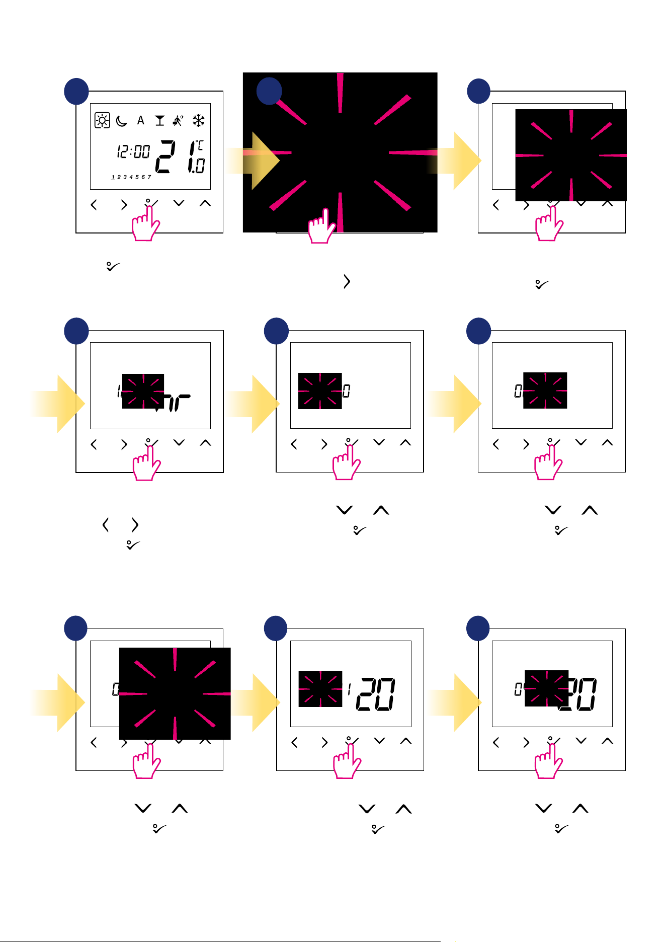
5.2 Time/Date
To set time/date follow steps below:
1
Set hour using and buttons.
Conrm by
button.
Set month using and
buttons. Conrm by
button.
Set year using and buttons.
Conrm by
button.
Set minutes using and buttons.
Conrm by
button.
Set day using and buttons.
Conrm by
button.
3
DATE settings will automatically appear after clock setup:
Hold button for 3 seconds to
enter the menu.
Go to the time and date settings
using button.
Choose time and date settings option
by button.
First, select time format (12/24h)
using and buttons. Conrm by
button.
7
8 9
4 5 6
2
3
3
23
3 sec.
Move forward using button.
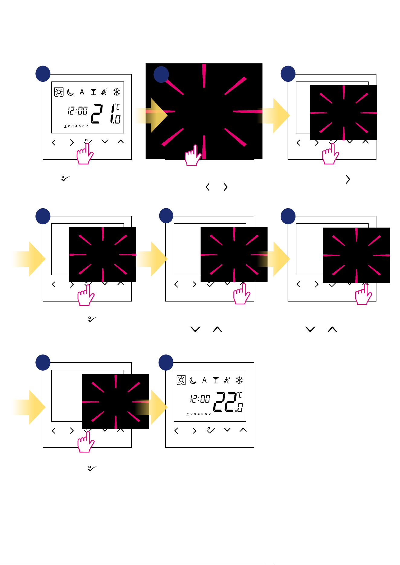
5.3 Thermostat calibration
Thermostat calibration is a function which allows user to recalibrate internal thermostat’s temperature sensor by a given number of degrees (in the range
from -3,0 °C to 3,0 °C in 0,5 °C steps). To calibrate thermostat’s temperature sensor please follow steps below:
1
4
7
6
Set temperature calibration value
using and buttons.
To increase/decrease value use
and buttons.
Go to the thermostat calibration
settings using and buttons.
5
2
3
8
Hold button for 3 seconds to
enter the menu.
Conrm by button.
Conrm by button.
Thermostat will go back to the main
screen after saving the settings.
3
24
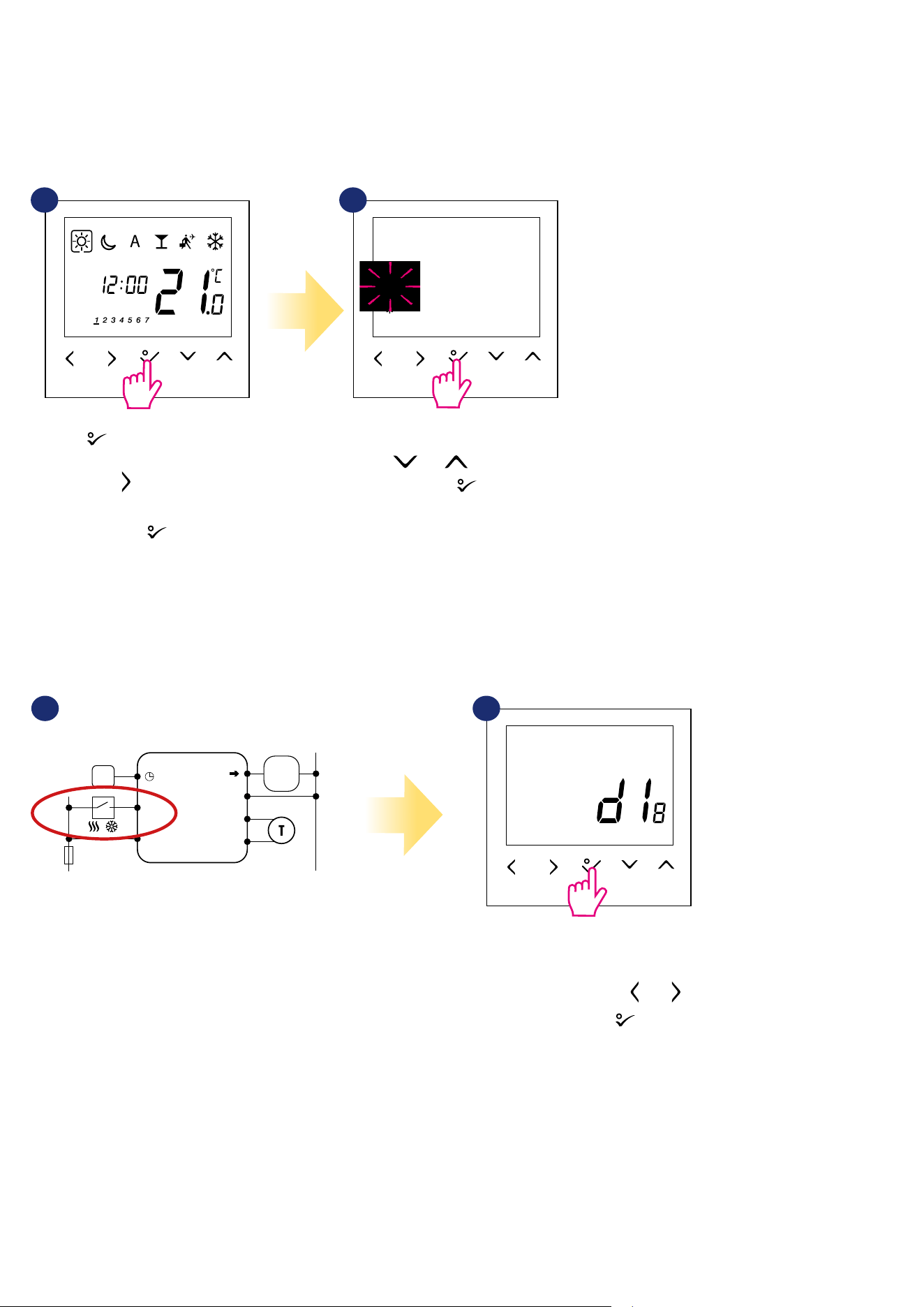
3 sec.
If we are using this option then
d18 parameter should be set to „1”.
Move in settings using and
buttons. Conrm by button.
Hold button for 3 seconds to
enter the menu.
Then use button to choose
heating/cooling settings.
Conrm by button.
5.4 Heat/cool mode change
The heating / cooling mode for the thermostat
can be changed manually or automatically via
„CO” terminal. If 230V power is applied to the
„CO” terminal - then thermostat automatically
switches to cooling mode.
Set thermostat for heating using
and buttons.
Conrm by button.
21
1 2
AUTOMATICALLY:
By external ON/OFF switch:
MANUALLY:
3
Wejście NSB
w regulatorze SLAVE
BTRP 230 KL08 NSB
L
S1
N
N
CO
L
SL
N
BTRP 230
Wyjście NSB
L
N
S1
N
CO
L
AC 230V
N
T30NC
/
NSB input in
SLAVE thermostat
NSB output
The heating / cooling mode for the thermostat can be changed manually or automatically via „CO” terminal. If 230V power is applied to the „CO” terminal
- then thermostat automatically switches to cooling mode. If you use this function in automatic mode, set the d18 parameter value to „1”.
25
3 sec. 3 sec.
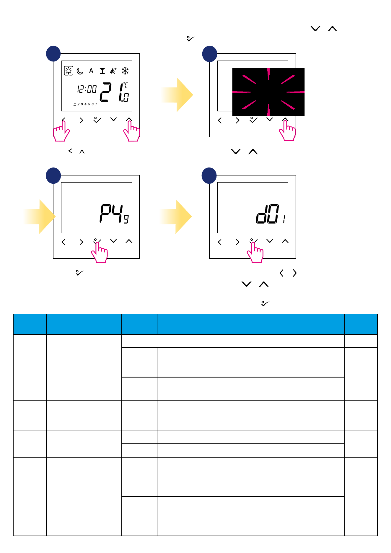
6. Installer parameters
To enter installer parameters please follow steps below. Please refer to parameters table description before any changes. Use or buttons to move
up or down between all parameters. Every change/selection conrm by button:
1
3
Use or to choose
code „49”.
Press button to conrm.
Select installer parameter by or
buttons. Use or buttons to
change parameter value.
Conrm choice by button.
4
2
Hold + buttons for 3 seconds
to enter the installer mode.
dXX Function
Parameter
Values
Description
Default
Values
d01 Heating Control
This parameter denes the algorithm of the room temperature control.
0
PWM (Pulse-width modulation) algorithm ensures reduction of overdrive
states and economic operation of the system. It is an advanced algorithm
designed to precisely maintain room temperature.
0
1 SPAN ± 0.25°C (± 0.5°F)
2
SPAN ± 0.5
°
C (± 1.0
°
F)
d02 Room temp. oset
-3.0°C to
+ 3.0°C
Oset room temperature measuring is a function which allows user to
recalibrate internal thermostat’s temperature sensor by a given number of
degrees (in the range from -3,0 °C to 3,0 °C in 0,5°C steps).
0.0°C
d03
OUT sensor probe (S1/S2)
0 Out sensor probe not connected
0
1 Out sensor probe connected
d04 Air sensor or Floor sensor
0
Air sensor: If parameter d03 is inactive (d03 = 0) then internal sensor
controls the temperature
Air sensor: If parameter d03 is active (d03 = 1) then internal sensor is
disabled and OUT sensor controls the temperature
0
1
Floor sensor: If parameter d03 is inactive (d03 = 0) then internal sensor
controls the temperature
Floor sensor: If parameter d03 is active (d03 = 1) then internal sensor is
disabled and OUT sensor controls the oor protection temperature
3
26
dXX Function
Parameter
Values
Description
Default
Values
d05 Cooling Control
1 SPAN ± 0.25°C (± 0.5°F)
2
2
SPAN ± 0.5
°
C (± 1.0
°
F)
d07 Valve Protection 1
Enable.
Valve protection function is intended to protect thermostatic valves against
getting stuck or jamming (e.g. in summer time when heating system is disa-
bled). If thermostat doesn’t send a signal for heating for a period of 7 days, then
heating is turned on for a very short period of time just to move the actuators.
1
d08
Frost Setpoint
5°C - 17°C
In Frost protection mode the thermostat is displaying actual room tem-
perature and maintain „frost protection” setpoint temperature specied
in thermostat settings. When thermostat works in Frost protection
mode then you have no possibilities to change temperature setpoint.
5.0°C
d09
12/24 Hour Format
0
12hours
1
1
24hours
d11
Daylight Saving Time
(DST)
0 O
1
1 On
d12
Maximum limitation of
heating setpoint
5°C - 35°C
This parameter allows to limit temperature setpoint range by setting
maximum setpoint for heating and cooling modes. Default temperature
setting range: 5⁰C - 35⁰C
35°C
d13
Minimum limitation of
cooling setpoint
5°C - 40°C
This parameter allows to limit temperature setpoint range by setting
minimum setpoint for heating and cooling modes. Default temperature
setting range: 5⁰C - 40⁰C
5°C
d14*
Floor sensor protection limit
(heating high limit-HL)
11°C - 45°C
Turn o relay output when oor sensing temp >
protecting limit, step is 0.5°C
27°C
d15*
Floor sensor protection limit
(heating low limit-LL)
6°C - 40°C
Turn on relay output when oor sensing temp <
protecting limit, step is 0.5°C
10°C
d16*
Floor sensor protection limit
(cooling)
6°C - 45°C
Turn o relay output when oor sensing temp <
protecting limit, step is 0.5ºC
6°C
d17 Preset program selection 1-5
Select one of these 5 default programs. Once selected, default program will
overwrite present program. Selected default program can be edited by the
user in the User Setting Mode.
1
d18 Heat/Cool Mode Selection
0 No connection
0
1 Connection
d19** Cooling Blocked
0 Cooling disabled
0
1 Cooling allowed
d20
Actuators loading selection
for dierent temperature
compensation.
1 x1 actuator loading
1
2 x2 actuators loading
3 x3 actuators loading
4 x4 actuators loading
5 x5 actuators loading
**Cooling Blocked - at „1” we block cooling for a single room until the device receives a heating command. During the blocking of the cooling function
no message is displayed.
*Parameters d14, d15, d16 will be available only if parameter d04 is active (d04=1).
**Please note!
d19 parameter will be available only if d18 is set on 1.
27
3 sec.
3 sec.
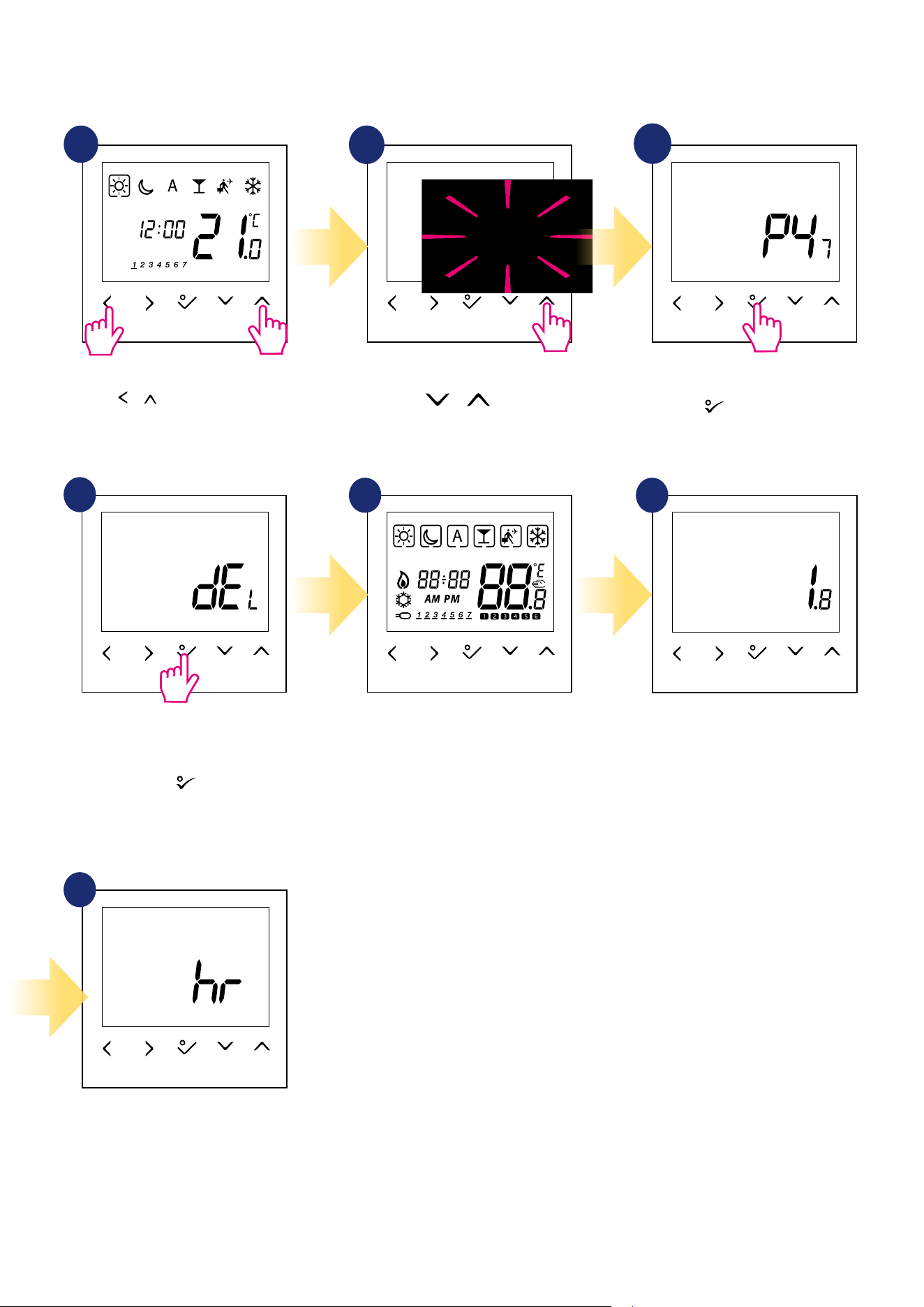
Hold + buttons for 3 seconds
to enter the installer mode.
7. Factory Reset
To RESET BTRP230V(50) thermostat to it’s factory default settings please follow steps below:
1
2
3
4
7
5 6
Wait few moments to nish factory
reset procedure...
...thermostat will display the
software version...
...after all - screen with time and
date selection will appear.
Use or buttons
to choose code „47”.
Press
button to conrm.
Select „del” and conrm choice by
pressing
button
.
3
28
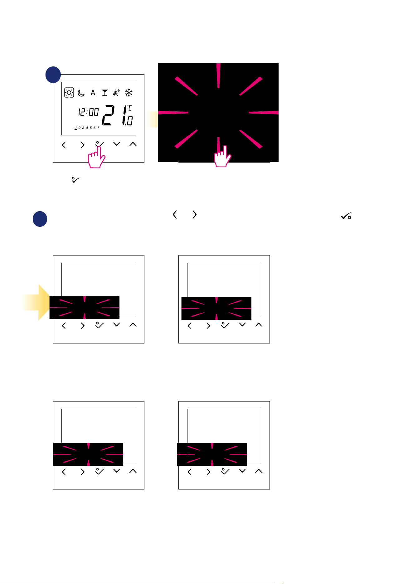
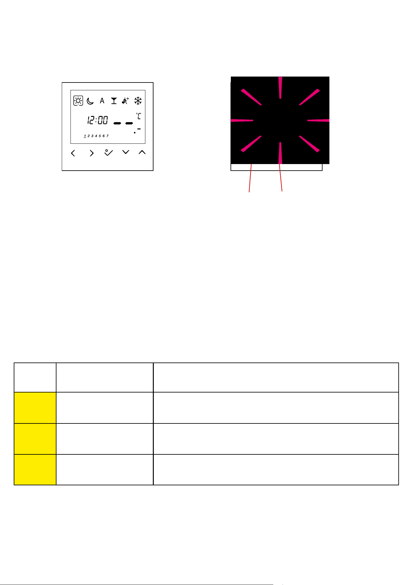
8. Error codes
Thermostat constantly monitors the operation of connected sensors. If it detects any failure then following error codes can be displayed.
Error code ERROR DESCRIPTION TROUBLESHOOTING
Err02
The maximum / minimum oor
temperature has been exceeded
• Set the heating / cooling medium temperature or change D14 / D15 parameter.
Err03 Floor sensor is faulty
• If oor sensor is connected to S1/S2 input, check the wiring.
• If oor sensor is not connected, check the D03/D04 parameters settings.
Err04 Floor sensor is shorted • Check oor sensor wire insulation for any damages. Sensor resistance for 25°C=10kΩ.
View of the display when the
external sensor has been selected
as air temperature measurement
(installer parameters D03 = 1 and
D04 = 0), but it is broken or not
connected.
Display view when an external
sensor has been selected as a oor
sensor (installer parameters D03 = 1
and D04 = 0). Applies to error codes
- Err02, Err03 and Err04. Check the
table below for a solution.
Number of errors Error code
29
Power supply 230 V AC 50 Hz
Rating max 0,5 A
Temperature setback Adjustable
Temperature range 5°C – 35°C
Span +/- 0,5°C
Storage temperature -20°C to +60°C
Ambient temperature 0 °C up to 45 °C
Degree of protection IP 30
CE conformity according to Class II ( EN60730 )
Housing material PC, V2
Color RAL 9010 pure white
Control method PWM algorithm
Hysteresis +/-0,5ºC or +/-0,25ºC
Connection Screw terminal
Puls-wide-modulation (PWM) Yes
Clock, Timer Yes, programmable
Heating and Cooling Yes, automatic modes changeover
through CO terminal
Parameter adjustment Yes, in Installer Mode
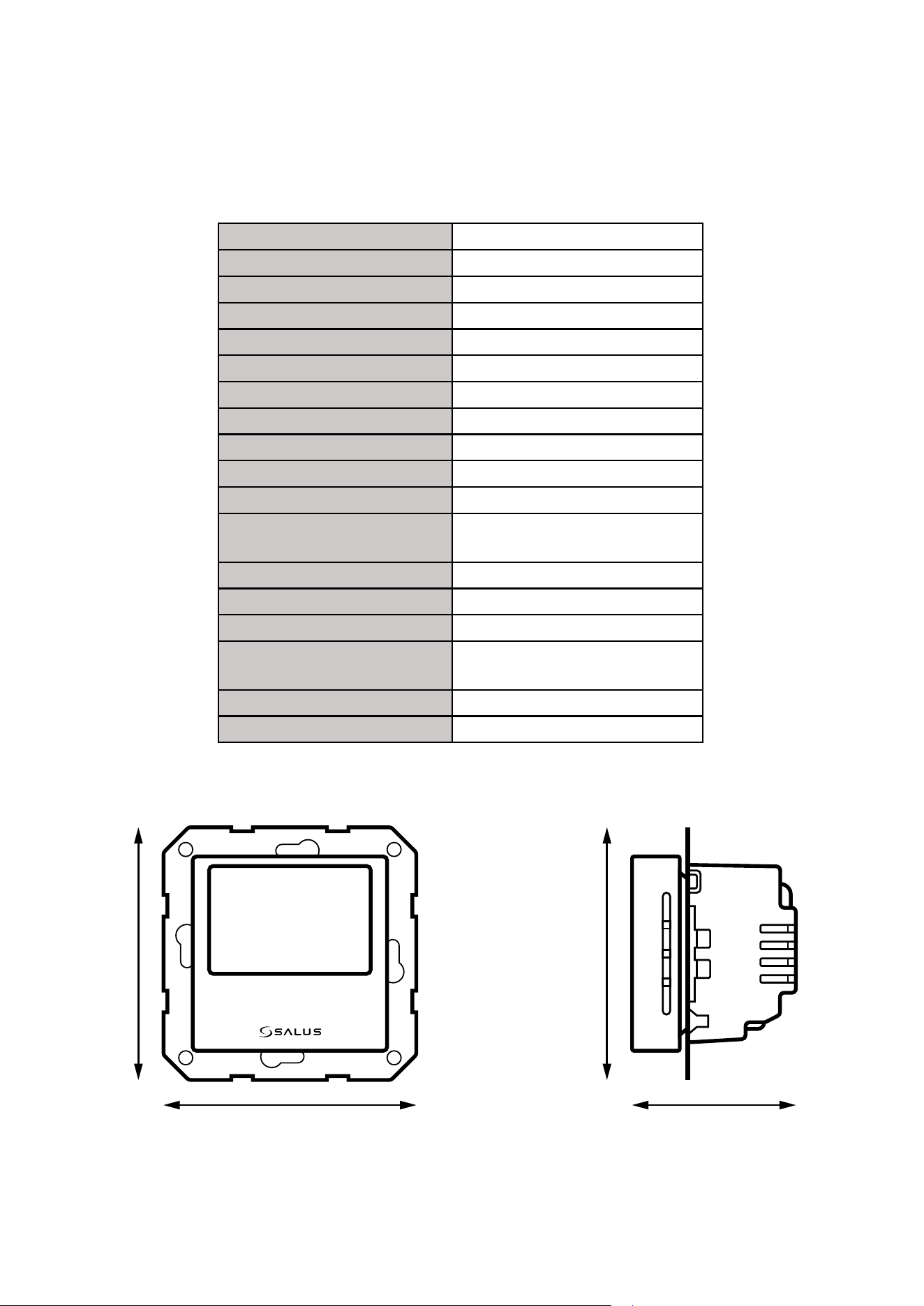
Dimensions 71mm x 71mm x 46mm
The BTRP230V(50) thermostat requires no special maintenance. Periodically, the outer casing can be wiped clean using a dry cloth (please DO NOT use
solvents, polishes, detergents or abrasive cleaners, as these can damage the thermostat). There are no user serviceable parts within the unit; any servicing
or repairs could only be carried out by Salus Controls or their appointed agents.
9. Cleaning and Maintenance
10. Technical Informations
71 mm
46 mm
71 mm
71 mm

30
11. Warranty
SALUS Controls warrants that this product will be free from any defect in materials or workmanship, and shall perform in accordance with its specication,
for a period of ve years from the date of installation. SALUS Controls sole liability for breach of this warranty will be (at its option) to repair or replace the
defective product.


32
PRODUCER:
SALUS Controls Plc
Units 8-10 Northfield Business Park
Forge Way, Parkgate
Rotherham
S60 1SD
United Kingdom
www.saluscontrols.com
SALUS Controls is a member of the Computime Group.
Maintaining a
policy of continuous product development SALUS Controls plc reserve the right to change
specification, design and materials of products listed in this brochure without prior notice.
Ver. 4
Issued: 14 IX 2020
Soft version: 1.8