VS10WRF/VS10BRF THERMOSTAT - FULL USER MANUAL

TABLE OF CONTENTS
1. Introduction ...............................................................................................................................................................5
1.1 Product Compliance ......................................................................................................................................................................5
1.2 Safety Informations .......................................................................................................................................................................5
2. Product Overview .......................................................................................................................................................6
2.1 Montage ........................................................................................................................................................................................6
2.2 Package content ............................................................................................................................................................................6
2.3 Proper thermostat location ...........................................................................................................................................................6
2.4 Connection Description (VS10WRF/VS10BRF thermostat) .............................................................................................................6
3. About ZigBee network ................................................................................................................................................7
3.1 ZigBee network - creation and work ..............................................................................................................................................7
3.2 Compatibility with SALUS devices (ONLINE AND OFFLINE) .............................................................................................................8
4. Before you start (rst power up) ..................................................................................................................................9
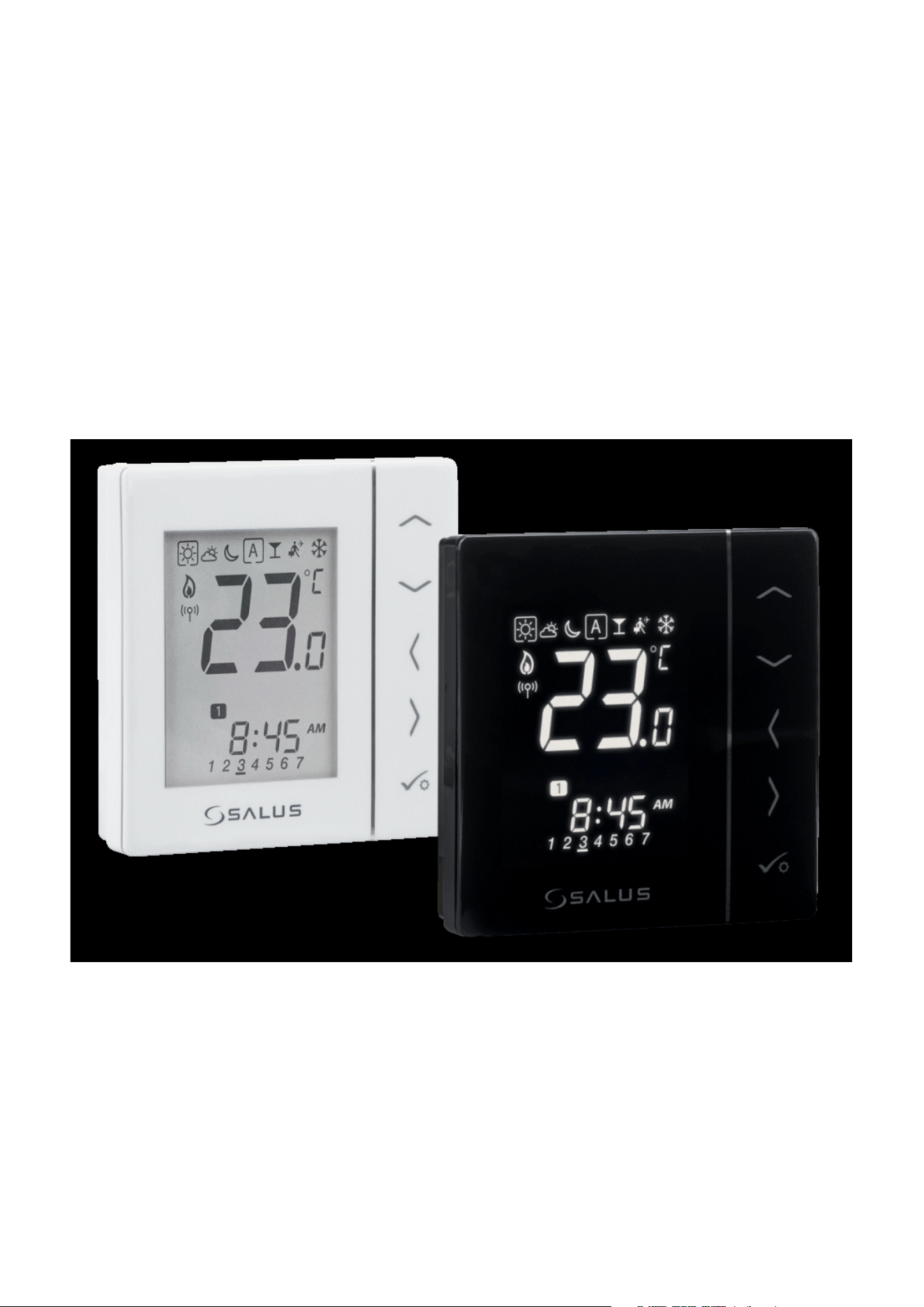
4.1 LCD icon description ......................................................................................................................................................................9
4.2 Button description .........................................................................................................................................................................9
4.3 First power up sequence, language choice and preparing to the pair process ..............................................................................10
5. Installation by SALUS Smart Home application (ONLINE MODE) .....................................................................................11
5.1 General informations about SALUS Smart Home application .......................................................................................................11
5.2 Conguration as a programmable thermostat ............................................................................................................................12
5.2.1 Pairing with underoor heating wiring centre (KL08RF/Control Box) ........................................................................12
5.2.2 Pairing with wireless TRV radiator head .....................................................................................................................15
5.2.3 Pairing with Smart Plug SPE600 ................................................................................................................................17
5.2.4 Pairing with Smart Relay SR600 .................................................................................................................................19
5.2.5 Pairing with RX10RF receiver .....................................................................................................................................21
5.3 Conguration as a hot water timer ..............................................................................................................................................23
5.3.1 Pairing with Room Extension Receiver (RX2) .............................................................................................................23
6. OPERATING in ONLINE MODE (by app) ..........................................................................................................................25
6.1 General informations ...................................................................................................................................................................25
6.2 App icons description ..................................................................................................................................................................25
6.2.1 Programmable thermostat ........................................................................................................................................25
6.2.2 Hot Water Timer .........................................................................................................................................................26
6.3 Change thermostat name (pencil icon) .......................................................................................................................................27
6.4 Work as a programmable thermostat ..........................................................................................................................................28
6.4.1 Setpoint temperature change ....................................................................................................................................28
6.4.2 Heat/Cool mode change (KL08RF connection) ...........................................................................................................29
6.4.3 Thermostat modes .....................................................................................................................................................30
6.4.3.1 Schedule mode .........................................................................................................................................30
6.4.3.2 Temporary override mode .........................................................................................................................34
6.4.3.3 Manual mode ...........................................................................................................................................34
6.4.3.4 Frost protection ........................................................................................................................................35
6.4.4 Key lock function ........................................................................................................................................................36
6.4.5 Compatibility with window/door sensor OS600 / SW600 ...........................................................................................37
6.4.6 Compatibility with Smart Plug SPE600 ......................................................................................................................38
6.4.7 Compatibility with Smart Relay SR600 .......................................................................................................................39
6.5 Work as a hot water timer (work modes) .....................................................................................................................................40
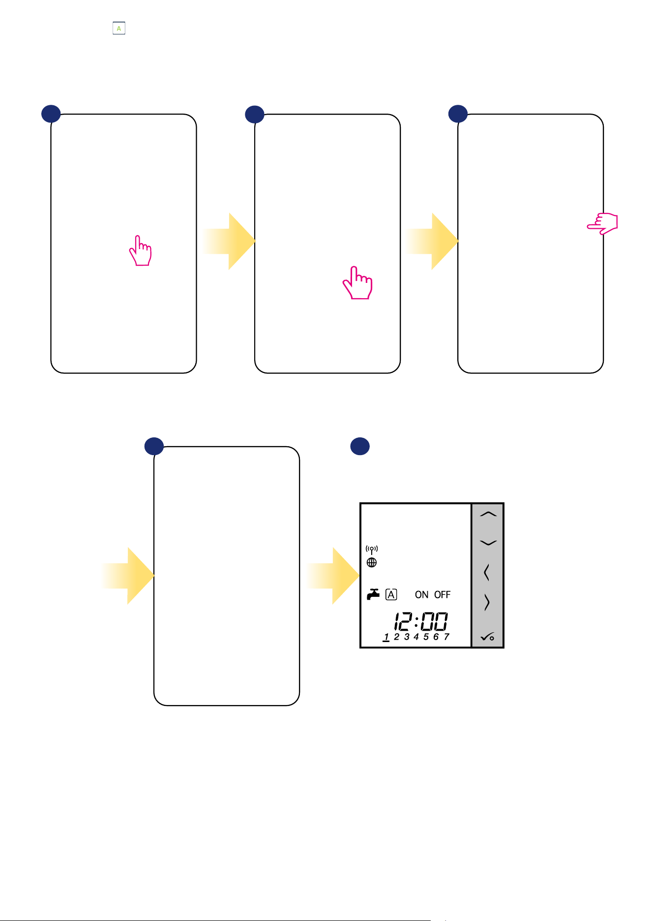
6.5.1 Turned ON mode - .................................................................................................................................................40
6.5.2 AUTO mode - .........................................................................................................................................................41
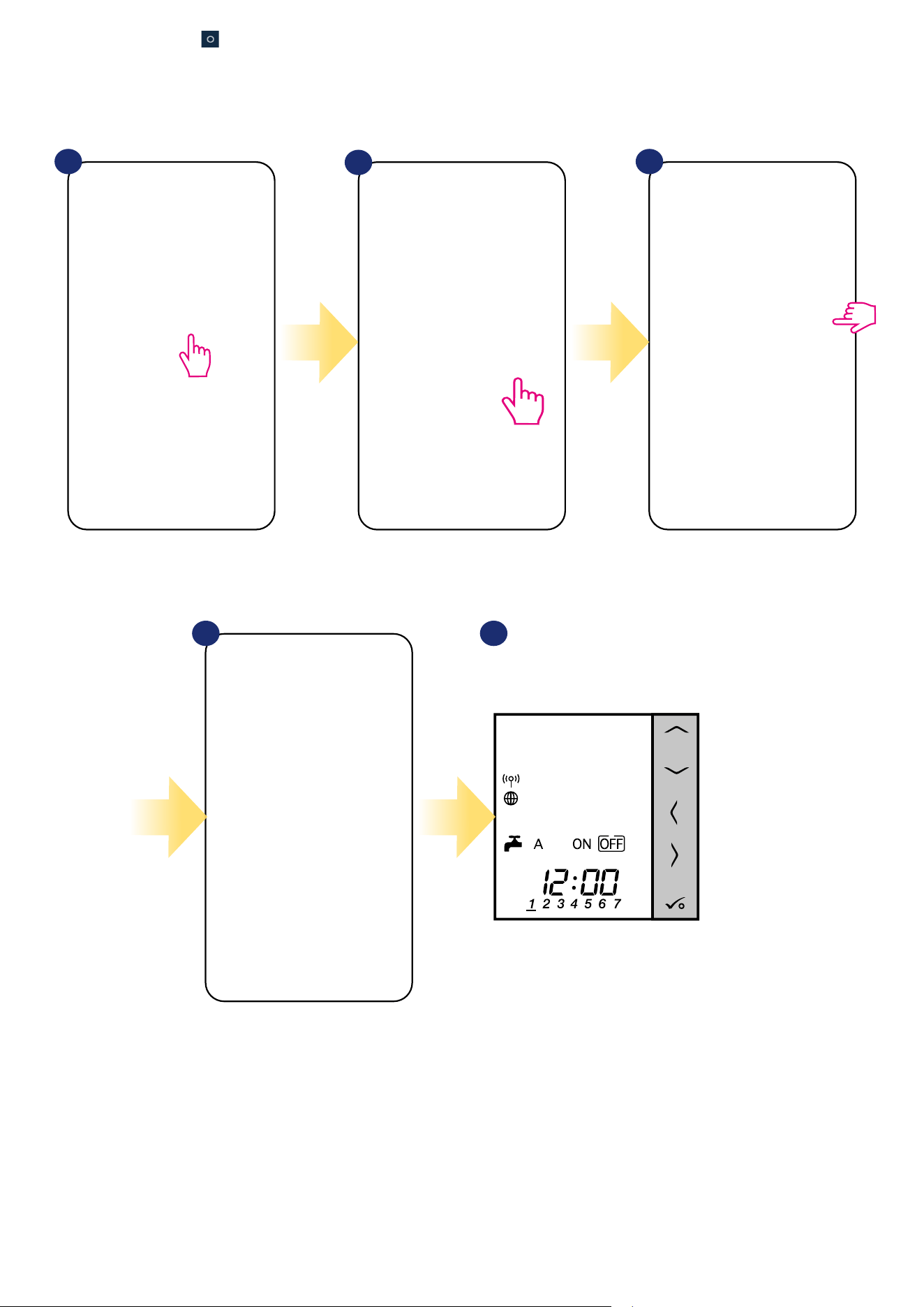
6.5.3 Turned OFF mode - ................................................................................................................................................42
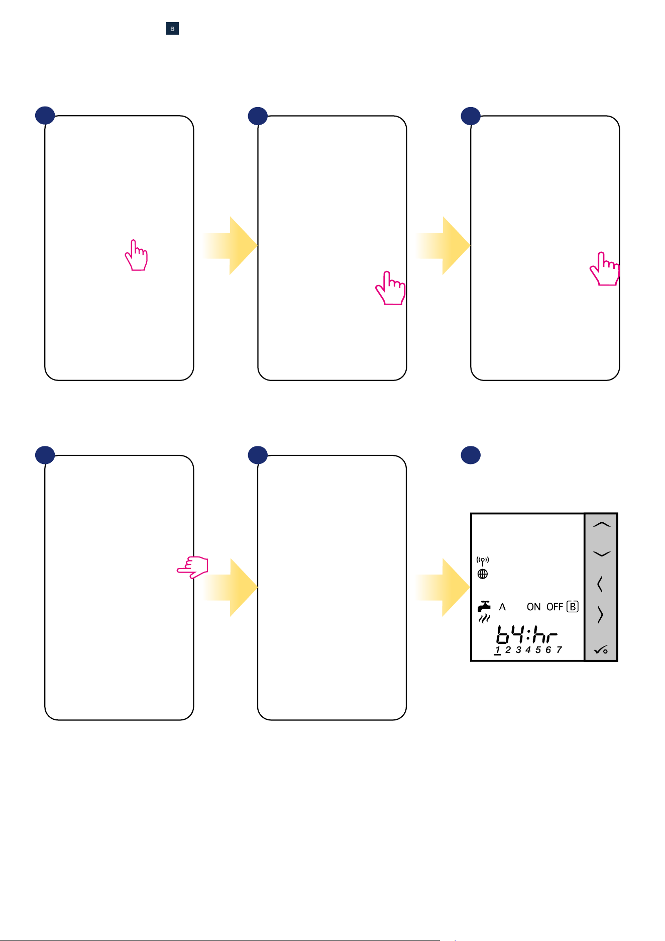
6.5.4 Temporarily ON mode - .........................................................................................................................................43

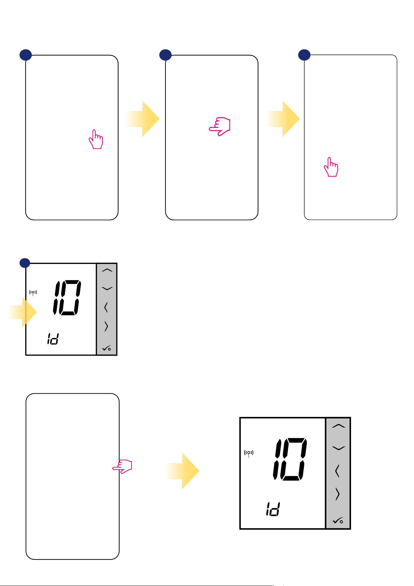
6.6 Identication mode .....................................................................................................................................................................44
6.7 Pinning/unpinning thermostat to/from application dashboard ..................................................................................................45
6.8 User settings (basic settings) .......................................................................................................................................................46
6.9 Admin settings (installer parameters) .........................................................................................................................................47
6.10 OneTouch rules (add/edit) ........................................................................................................................................................48
6.11 Error codes (exclamation mark in app) ......................................................................................................................................52
6.12 Wireless signal strength test ......................................................................................................................................................53
6.13 Factory reset (removing thermostat from the app and ZigBee network) ...................................................................................54
7. Installation in OFFLINE MODE without SALUS SmartHome application ..........................................................................56
7.1 General informations .................................................................................................................................................................56
7.2 Pairing with underoor heating wiring centre (KL08RF/Control Box) ..........................................................................................57
7.2.1 Available operation modes .........................................................................................................................................57
7.2.2 Grouping - installation of the thermostat as a group controller - MASTER - or as a group thermostat (SLAVE) ...........60
7.2.3 Installation as a programmable thermostat ...............................................................................................................62
7.2.4 Replace the zone assigned to another thermostat .....................................................................................................63
7.3 Pairing with wireless TRV radiator head ......................................................................................................................................64
7.4 Pairing with RX10RF receiver .......................................................................................................................................................66
7.5 Conguration as a Hot Water timer .............................................................................................................................................67
7.5.1 Pairing with Room Extension Receiver (RX2) .............................................................................................................67
8. OPERATING in OFFLINE MODE ......................................................................................................................................69
8.1 Work as a programmable thermostat ..........................................................................................................................................69
8.1.1 Work modes ...............................................................................................................................................................69
8.1.2 Heat/cool mode change (KL08RF connection) ............................................................................................................70
8.2 Work as a hot water timer with RX10RF receiver .........................................................................................................................71
8.2.1 Work modes ...............................................................................................................................................................71
8.3 User settings (basic settings) .......................................................................................................................................................72
8.3.1 Schedule mode - programming schedule ...................................................................................................................72
8.3.2 Time/Date ..................................................................................................................................................................74
8.3.3 Thermostat calibration ...............................................................................................................................................75
8.3.4 Key lock function ........................................................................................................................................................76
9. Installer parameters .................................................................................................................................................77
10. Factory Reset ..........................................................................................................................................................79
11. Error codes (error codes description with possible solutions) ......................................................................................80
12. Cleaning and Maintenance ......................................................................................................................................83
13. Technical Informations ............................................................................................................................................83
14. Warranty ................................................................................................................................................................84


5
This product complies with the essential requirements and other relevant provisions of Directives 2014/53/EU and 2011/65/EU. The full text of the EU
Declaration of Conformity is available at the following internet address: www.saluslegal.com.
• Before starting installation work and before using the product, read the entire manual.
• The information contained in the instructions is essential for proper functioning.
• To avoid accidents resulting in personal injury and material damage, please follow all safety precautions, specied in this manual.
• The device should not be used by people with limited mental, sensory or mental abilities, without experience, of insucient knowledge as well as
children.
• Do not use an unassembled device (eg without a cover).
• The device may only be opened by a qualied person.
• Keep electrical devices out of the reach of children and ensure that they do not play with it. Children should not be left unattended. If necessary,
disconnect the control system for the entire room.
• Do not leave the packaging, cabinet, or any loose parts of the device unattended, as they pose a risk to children.
WARNING!
• Installation must be carried out by a qualied person with appropriate electrical qualications in accordance with standards and regulations in force in
the given country and in the EU.
• Never try to connect the device other than as described in the manual.
• Before assembly, repair or maintenance as well as during any connection works it is absolutely necessary disconnect the mains supply and make sure
that the terminals and electric wires are not live.
• The device may not be exposed to extreme temperatures, strong vibrations or subjected to mechanical shock.
• The device should not be used in unfavorable environmental conditions or in rooms where there is a concentration of ammable gases, fumes or dust.
WARNING!
• There may be additional protection requirements for the entire installation that the installer is responsible for maintaining.
1. Introduction
1.1 Product Compliance
1.2 Safety Informations
Care for the natural environment is of paramount importance to us. The awareness that we manufacture electronic devices obliges us
to dispose of used electronic components and devices safely. Therefore the company has received a registration number issued by the
Chief Inspector for Environmental Protection. The crossed out symbol the trash can on the product means that the product must not be
disposed of with ordinary waste containers. Sorting waste for recycling helps to protect the environment. It is the user’s responsibility
to surrender used equipment to a designated collection point for recycling waste from electrical and electronic equipment.

6
2.1 Montage
2.2 Package content
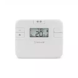
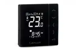
1) VS10WRF/VS10BRF thermostat
2) Short instructions
3) Mounting screws
2.3 Proper thermostat location
Please note:
Wall mounting
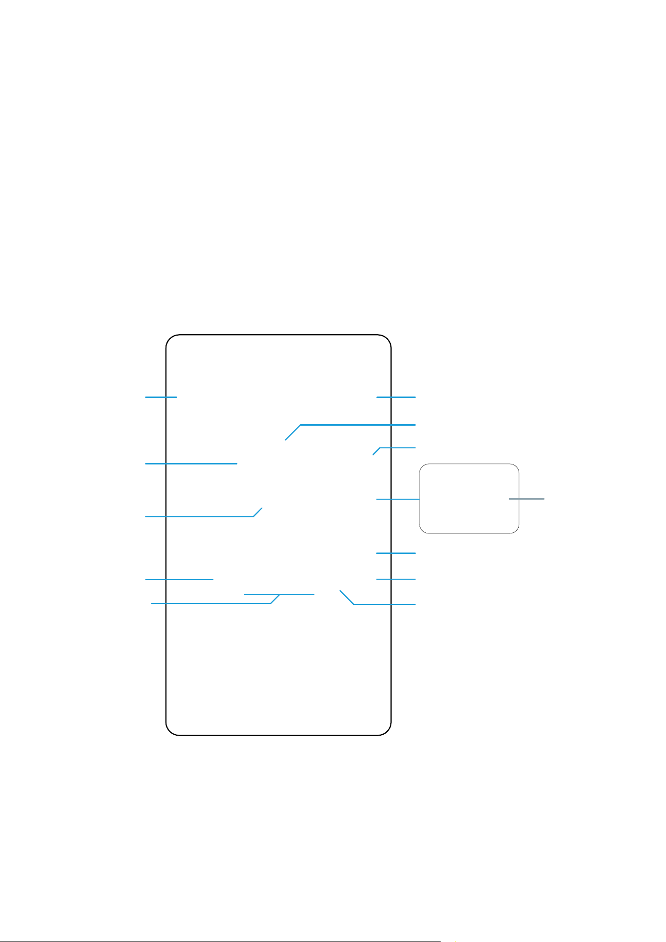
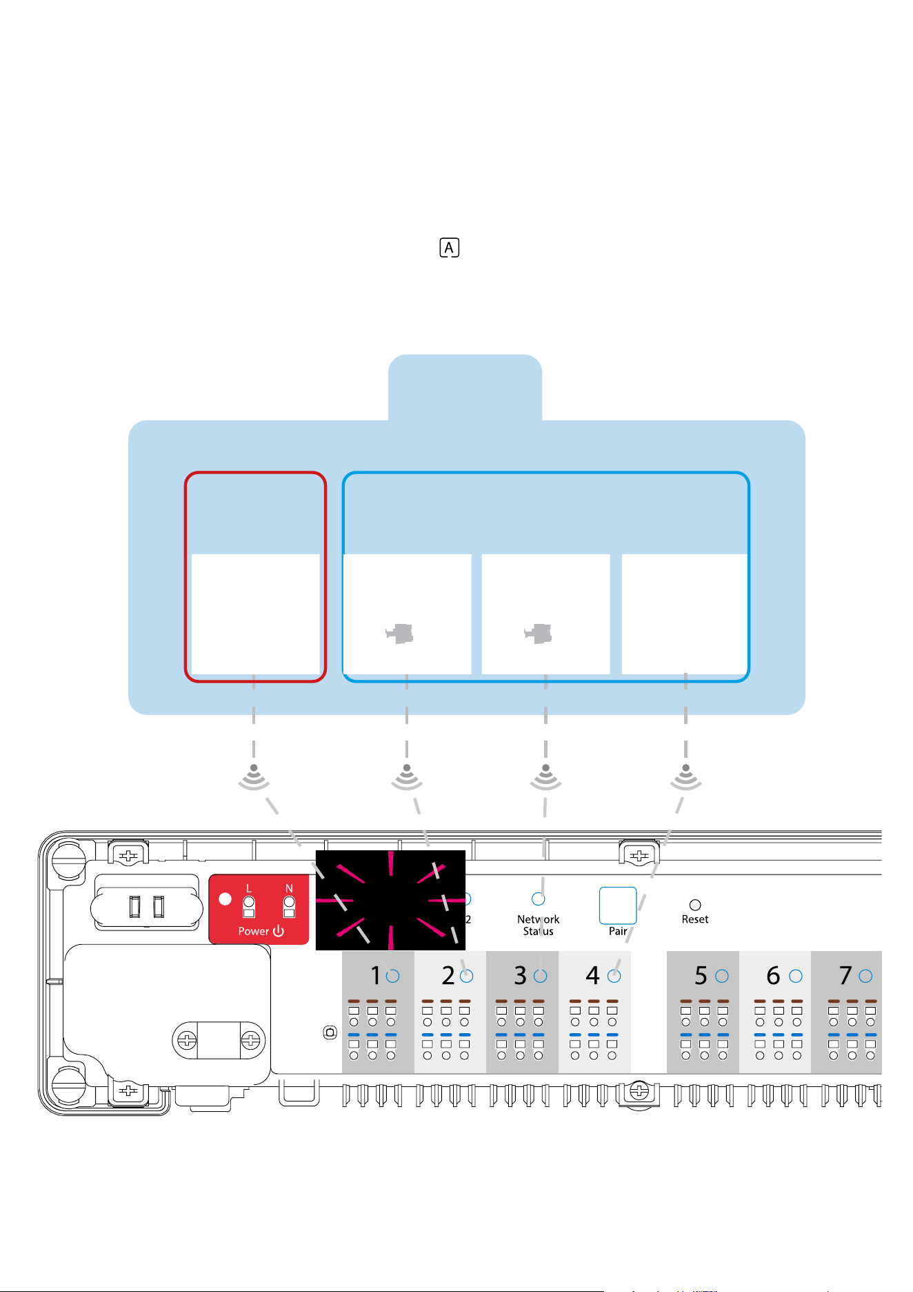
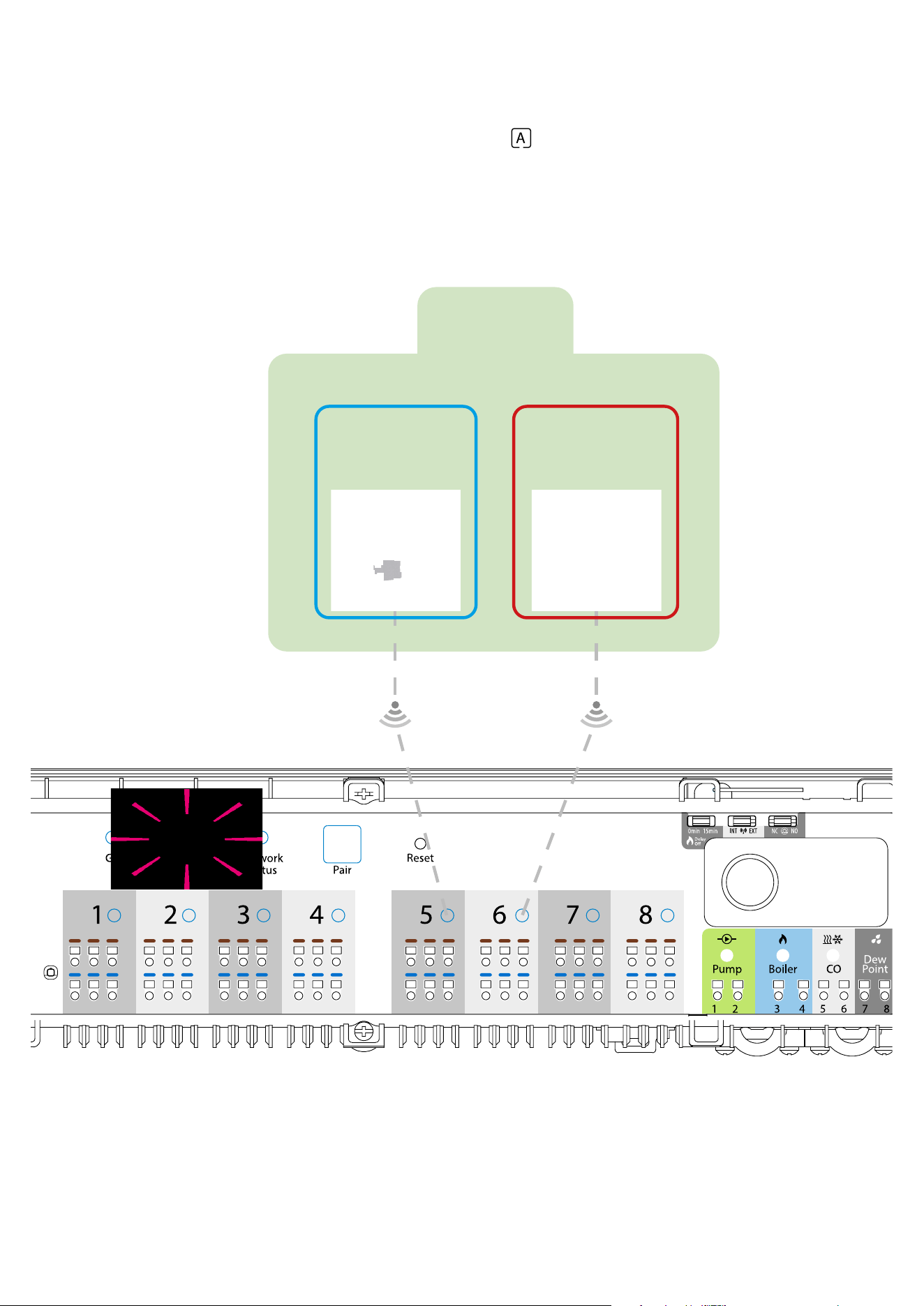
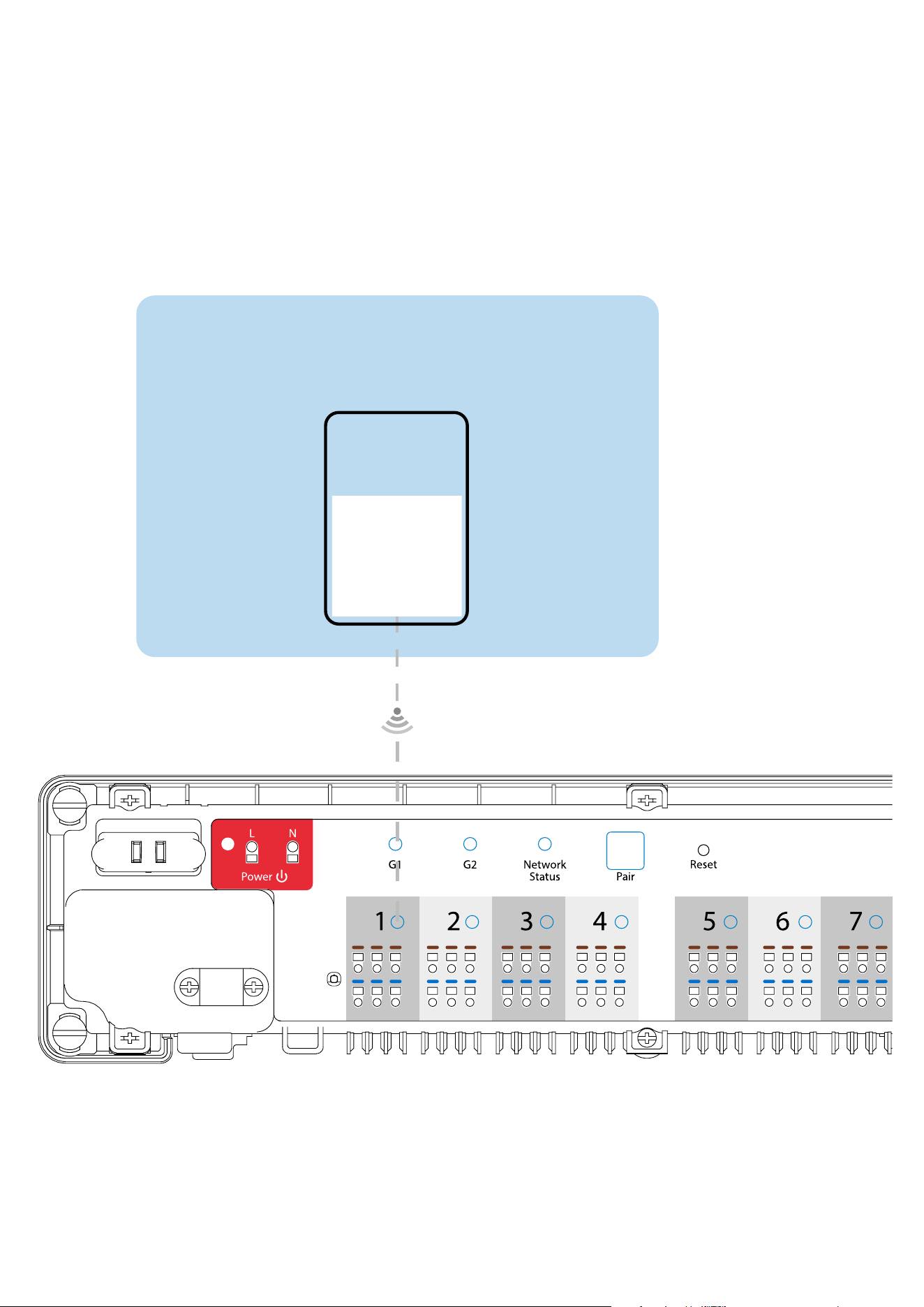
2.4 Connection Description (VS10WRF/VS10BRF thermostat)
1, 2 terminals:
- air or oor temperature sensor
- external volt-free contact to connect any ON/OFF switch or occupancy
sensor (Hotel card)
- external hot water thermostat
Symbols explanation:
S – volt-free contact
T – temperature sensor eg. FS300
L, N – power supply 230V AC
Mounting: to mount thermostat you can use accesories included with the set (mounting screws). Remove back cover to mount the plate to the wall.
Now please insert the batteries inside the thermostat. After this just attach thermostat to the plate right into designed holes in the plate.
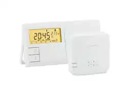
VS10WRF / VS10BRF is a room temperature thermostat that is used for wireless control of iT600 series devices such as: KL08RF wiring centre, TRV
radiator valve and RX10RF boiler receiver. In combination with Universal Gateway UGE600 this regulator can be controlled over the Internet using SALUS
SmartHome app (Online mode). Without Internet connection (Oine mode) thermostat works locally, but its communication with other devices must be
done through the coordinating unit - CO10RF.
The ideal position to thermostat mounting is about 1,5m under oor level far from heating or cooling sources. Thermostat can’t be
exposed to sunlight or any extreme conditions like for example draft.
Because of re and explosion risk there is not allowed to use thermostat in atmosphere of explosive gases and ammable liquids (eg coal dust). In case
if any of listed dangers occur you have to use additional protection measures – anti-dust and explosive gases (tight cover) or prevent their formation.
Furthermore, thermostat can’t be used in condensation of water vapor conditions and be exposed to water action.
1 2
3
2. Product Overview

7
3. About ZigBee network
3.1 ZigBee network - creation and work
ZigBee is a wireless network based on IEEE 802.15.4 standard and it’s communication takes place in the 2.4 GHz band. The network is based on a mesh
topology, which allows for a very large range and high reliability. The maximum range of direct communication between two network nodes (devices) is
about 100m in open space.
The devices included in the ZigBee network are divided into three types:
- coordinator - there can only be one such device in each network. It acts as a connection node for all devices;
- router (repeater) - this device is powered by 230VAC, with functionality similar to classic network routers, and it’s task is to forward data packets and
increase the range of the network;
- terminal device - battery powered, sends data to the coordinator (also through the router) to which it is connected. It is usually put to sleep tempora-
rily, which helps reduce energy consumption.
Built-in security in the ZigBee protocol (ISO-27001 and SSAE16 / ISAE 3402 Type II - SOC 2 certication) ensure high transmission reliability, detection and
removal of transmission errors, as well as connectivity between established priority devices.
Security measures include:
- devices authenticated using a unique key pair;
- encrypted communication between the mobile application and the device;
- data encryption - HTTPS encrypted using TLS, UDP channel with AES-128 encryption;
- layered access control to prevent tampering with one device threatening the entire system.
The ability to work many devices at a short distance from each other was achieved through the use of radio transmission of the spread spectrum signal.
The main advantages of devices working in the ZigBee system are two-way communication and minimization of energy consumption, which in many
cases allows them to be powered from 230V AC.
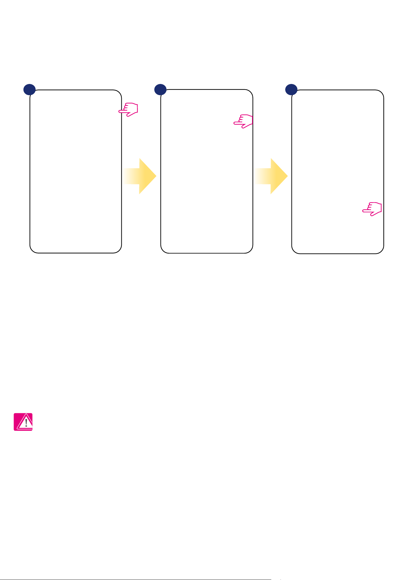
Four Simple steps to create ZigBee network:
1.
Coordinator Installation - Universal Gateway for
ONLINE and OFFLINE systems with internet application
or CO10RF for only OFFLINE systems without application.
2.
Now - add any device you want powered 230VAC.
Note to locate it as near coordinator as possible.
3.
Now you can increase range of ZigBee network
by adding more devices powered 230 VAC.
4.
To extend your network you can add more battery
devices and accesories.
8
3.2 Compatibility with SALUS devices (ONLINE AND OFFLINE)
COMPATIBILTY WITH OTHER SALUS CONTROLS DEVICES
VS10 thermostat can work in ONLINE or OFFLINE mode.
At rst step you need to decide in which mode your thermostat will work.
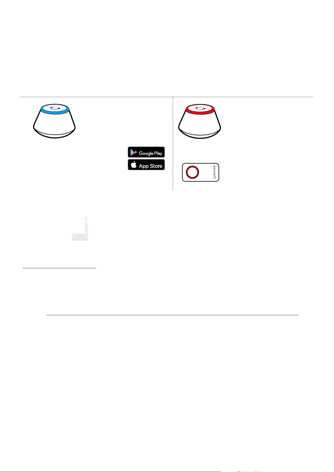
ONLINE MODE OFFLINE MODE
Universal Gateway is
CONNECTED TO THE INTERNET
You can congure and use all your
devices in the Smart Home App
Download the Smart Home App
on your iOS or Android device
for remote access to your SALUS
equipment.
SALUS
Smart Home
CO10RF Coordinator - You can use
standard ZigBee network coordinator
to install and use your devices.
Universal Gateway is NOT
CONNECTED TO THE INTERNET
You can use your devices locally
without the Smar tHome App. Gateway
works in this mode as standard ZigBee
coordinator.
Compatibile devices:
KL08RF wireless wiring
centre for 8-zone
underoor heating.
KL04RF extension
TRV
(Thermostatic
Radiator Valve) with
wireless communication.
RX10RF
receiver
SR600
Smart Relay
SPE600
Smart Plug
GET IT ON
Download on the
OR
Other SmartHome devices/accessories
Only with Online Mode
Water leak sensor
WLS600
Double/single OneTouch button
SB600/CSB600
Smoke detector
SD600
Window/door Sensor
SW600 or OS600
RS600
Roller shutter
RE600
ZigBee network signal repeater
(only with UGE600)
RE10RF
ZigBee network signal
repeater
9
4. Before you start (rst power up)
4.2 Button description
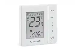
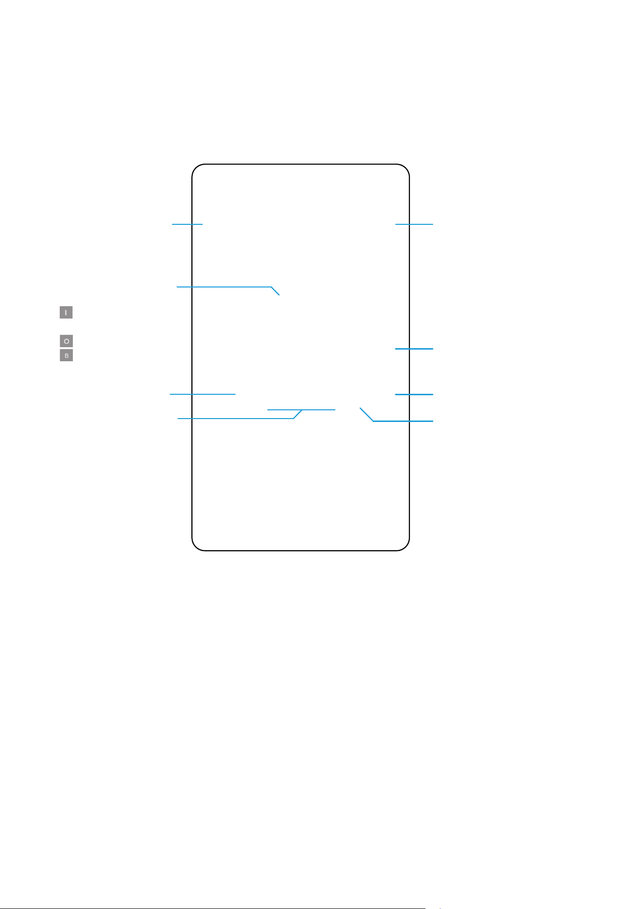
4.1 LCD icon description
1. Comfort temperature
2. Standard temperature
3. Economic temperature
4. Automatic mode
5. PARTY mode
6. Holiday mode
7. Frost protection mode
8. Temperature unit
9. Group controller
10. Manual mode / override temp.
11. Current / set temperature
12. Program number
13. AM / PM
14. Lock function
15. Clock
16. Day indicator
17. Settings
18. Low battery indicator
19. External temperature sensor
20. Hot water heating
21. Modes for Hot Water
22. Cooling mode ON
23. Internet connection indicator
24. Gateway wireless connection
25. Heating mode ON
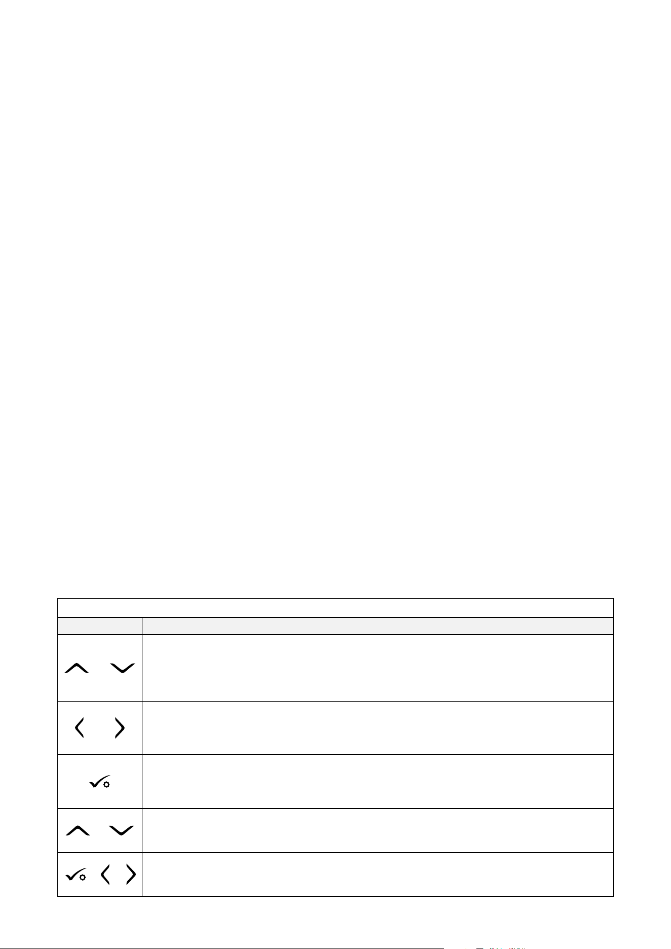
Button Description
Button Function
OR
1. Increase or decrease setpoint temperature.
2. Increase or decrease Day, Clock, Timer, Party, Holiday and Boost.
3. Select installer parameter value.
OR
1. Mode selection.
2. Moving between parameters.
1. OK key: Short press to conrm selection.
2. Long press to save and exit.
3. Long press to enter the user settings.
+
Hold down these buttons to lock or unlock the keyboard.
+ +
Hold down these buttons to enter installer parameter settings.
10
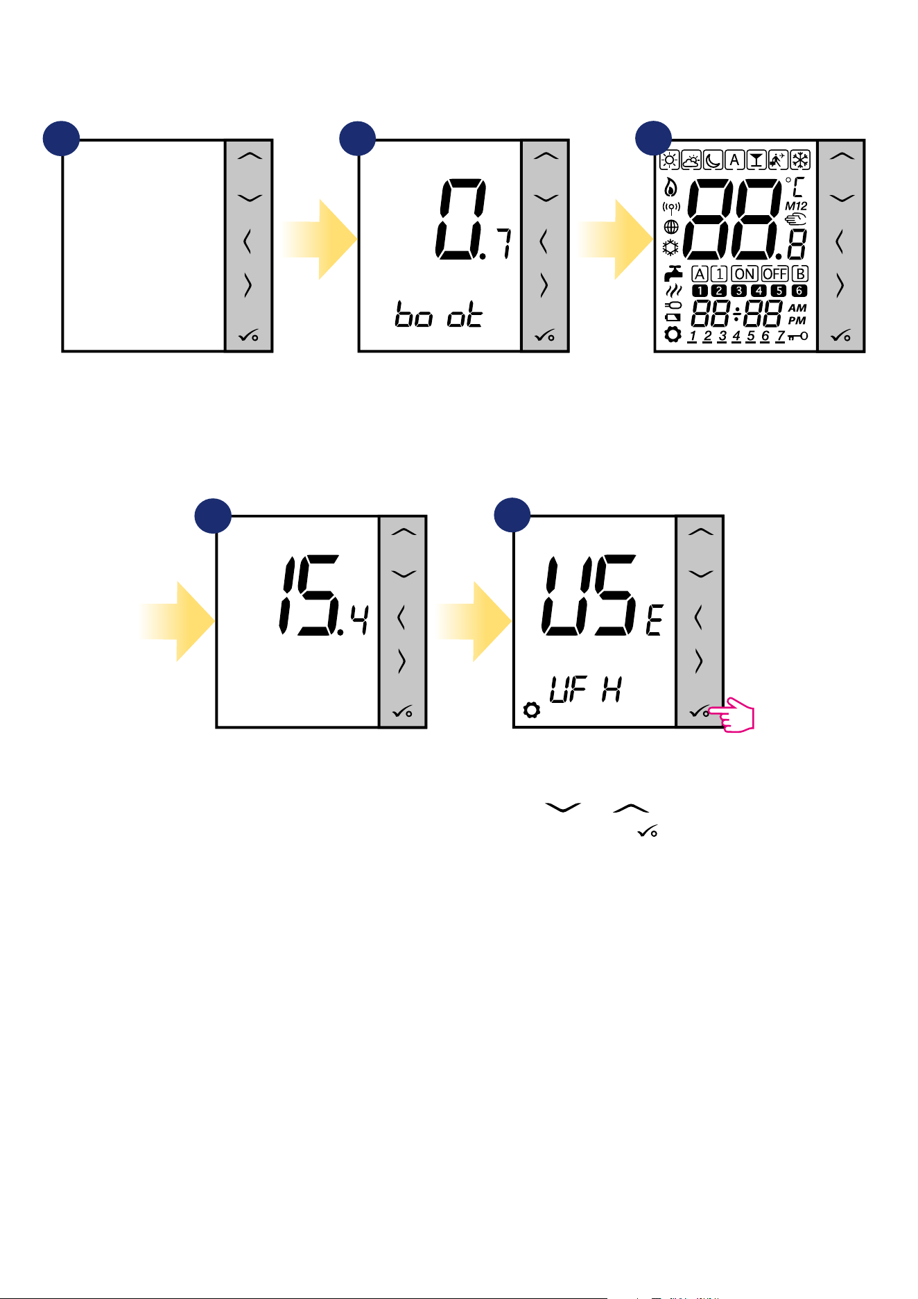
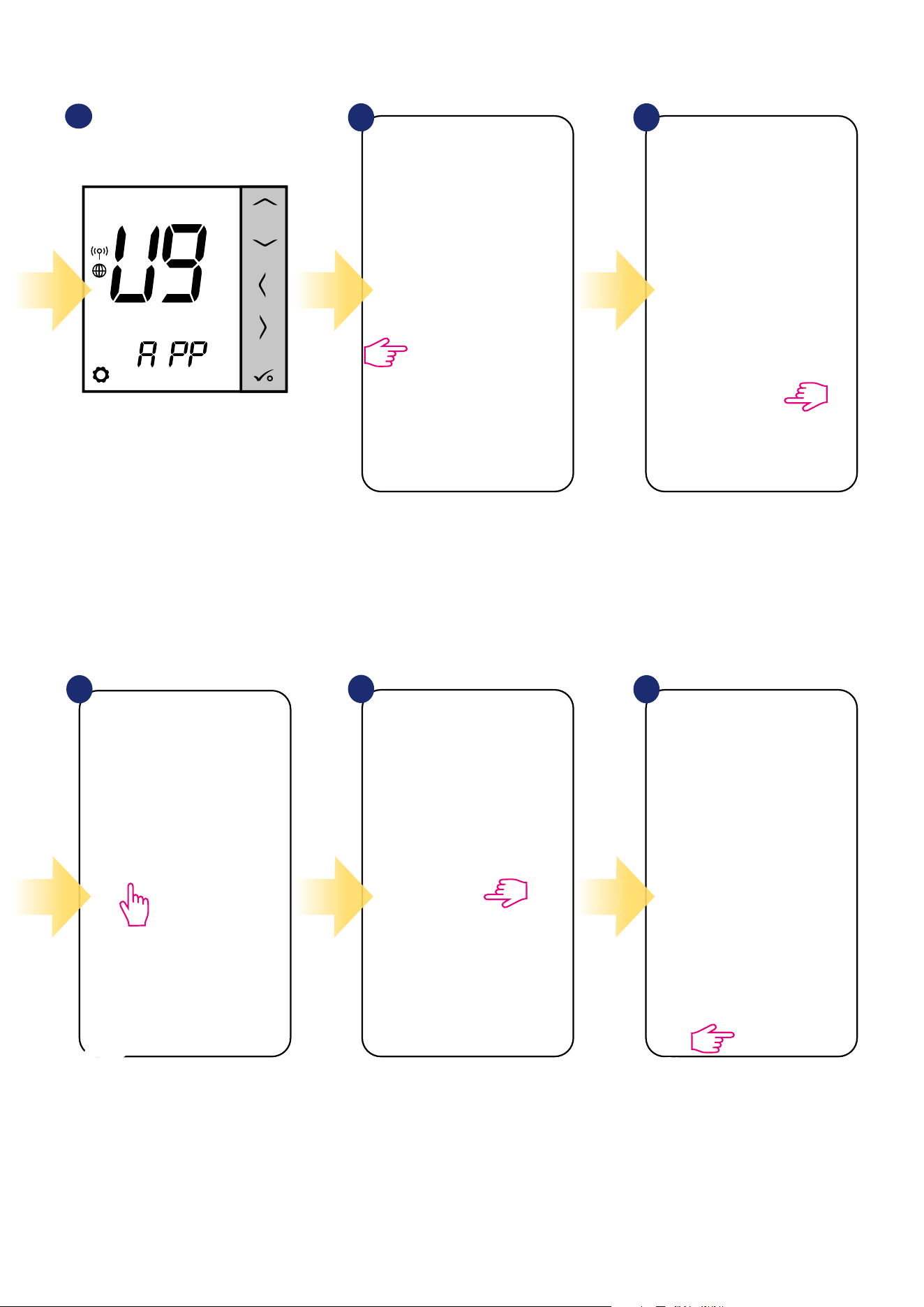
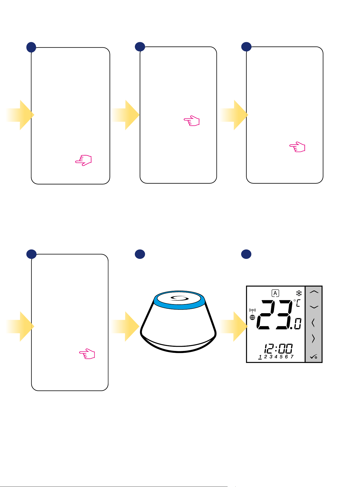
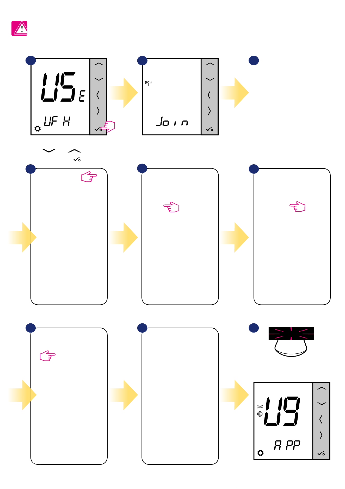
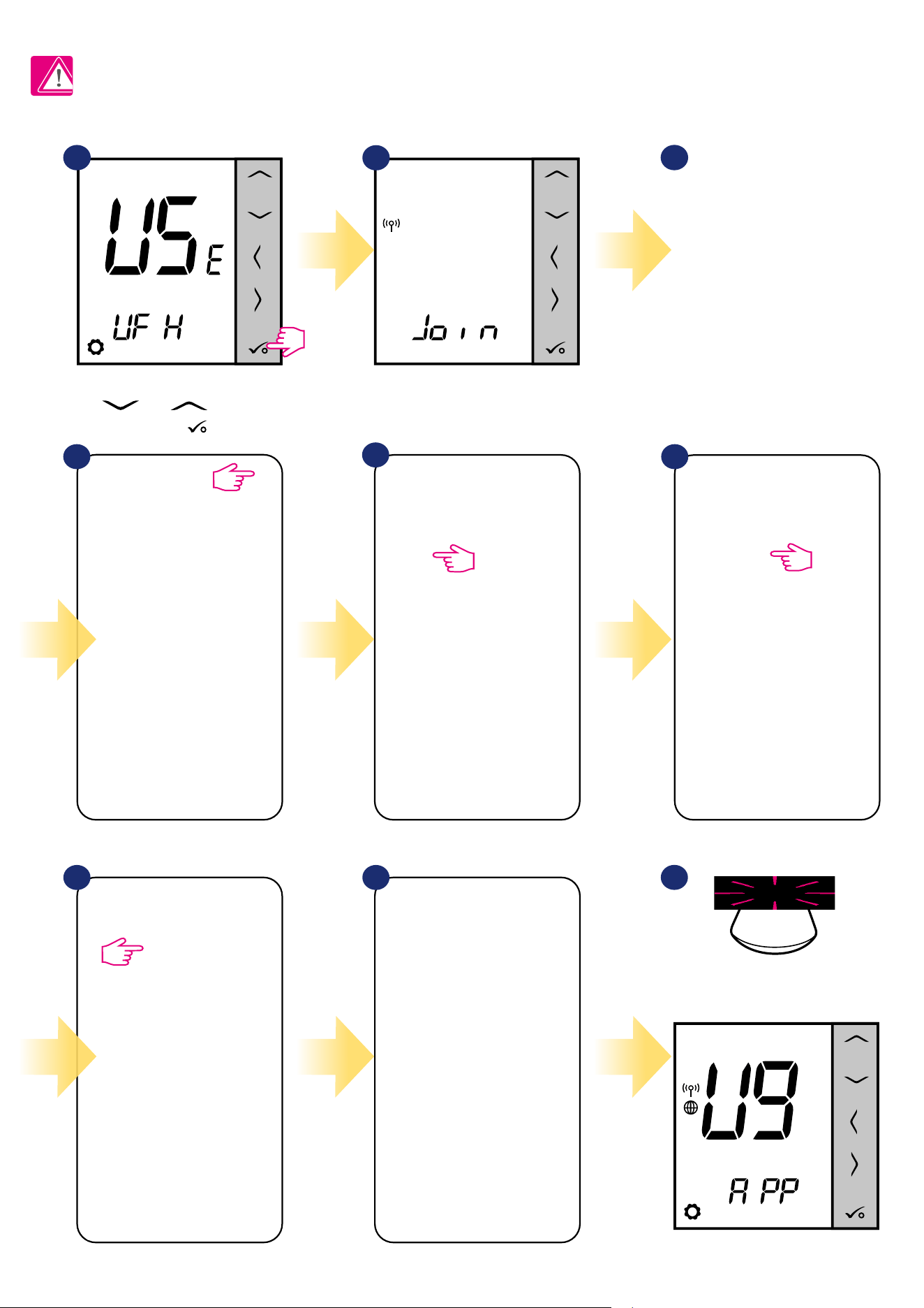
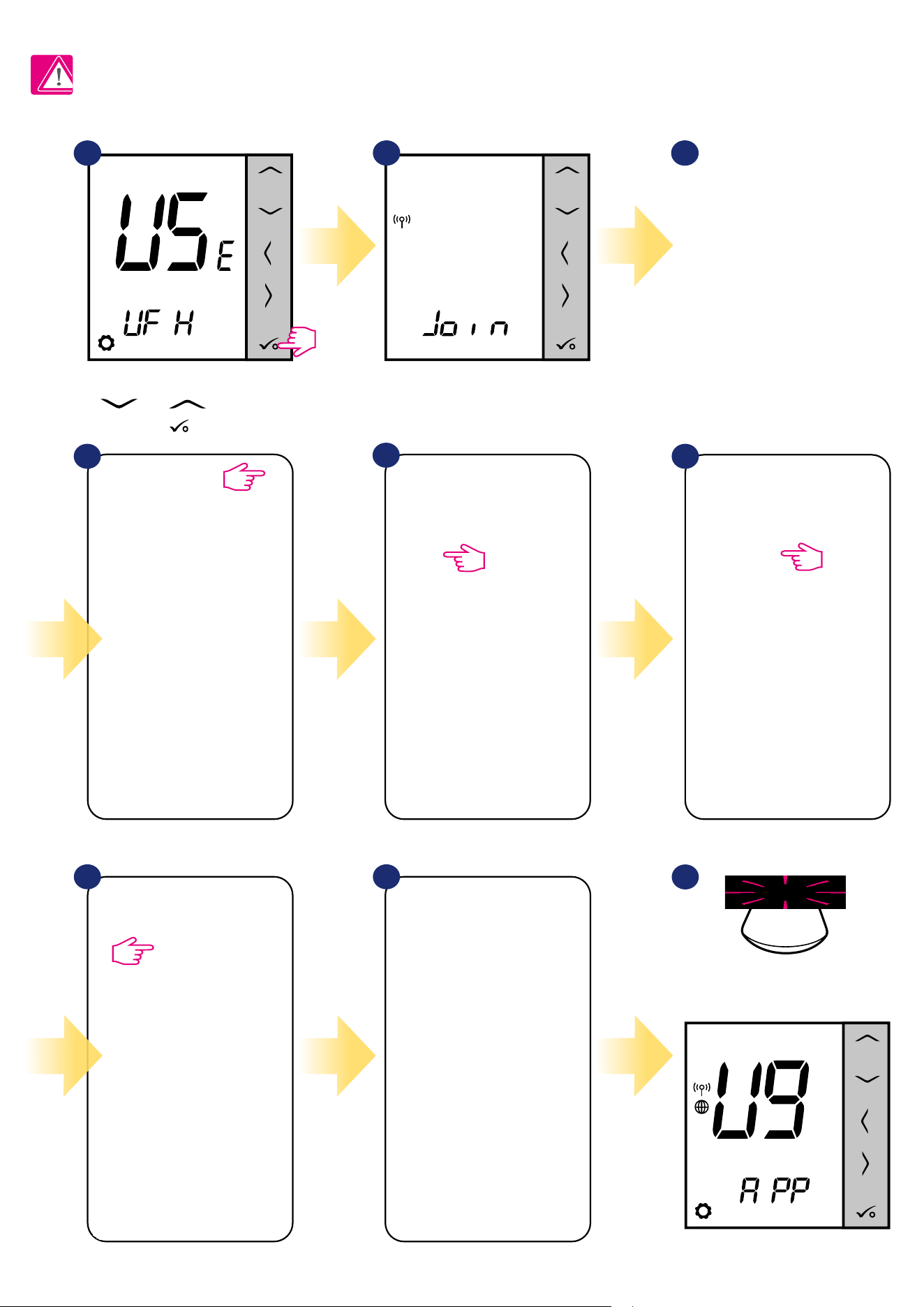
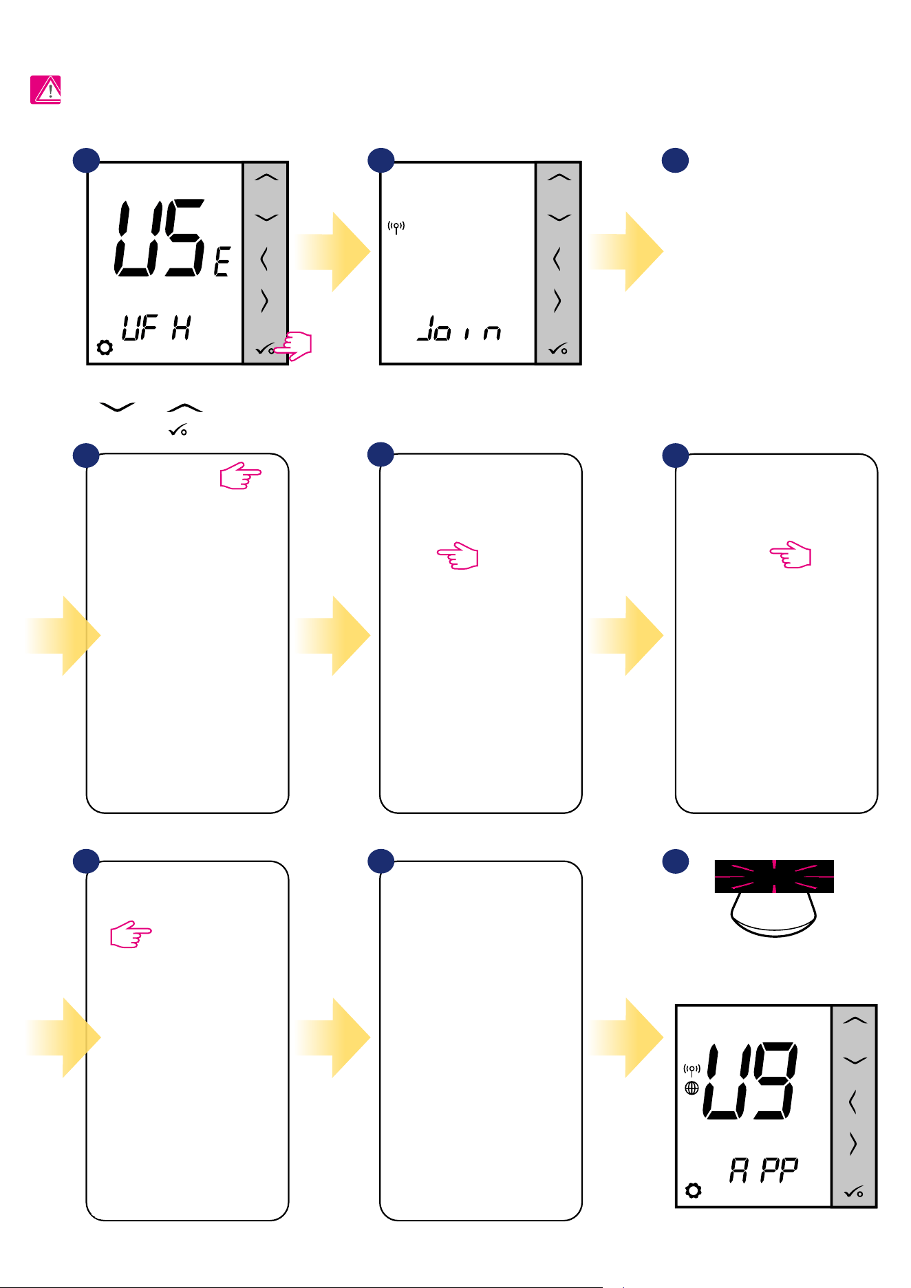
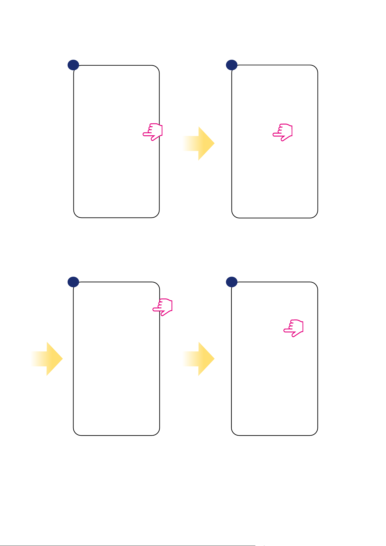
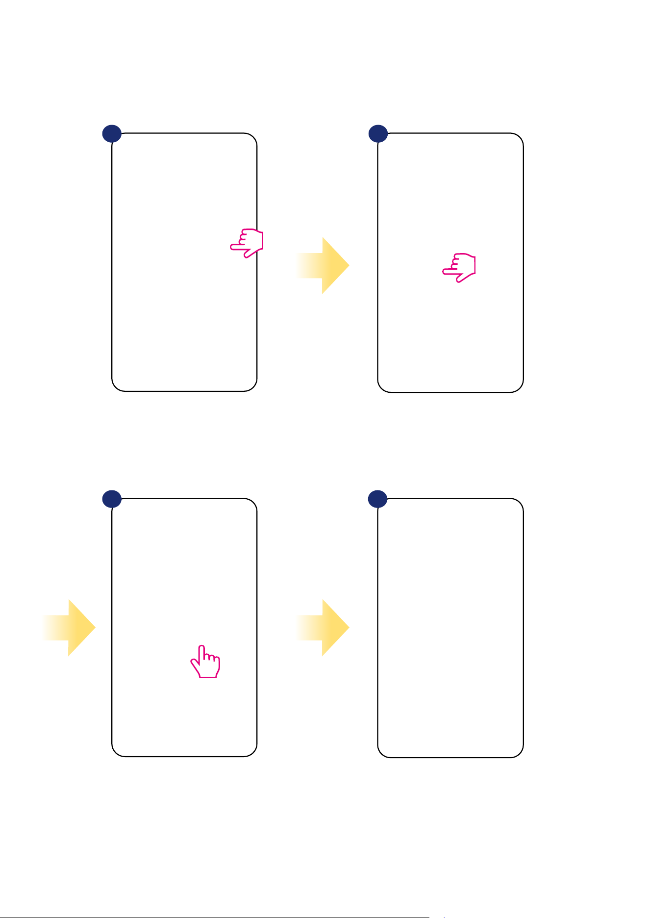
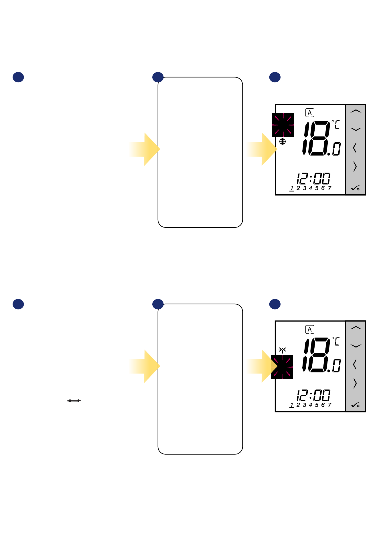
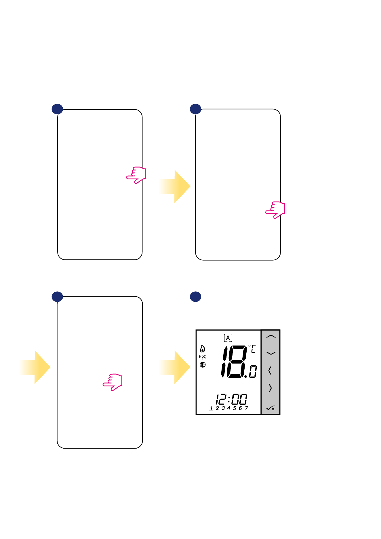
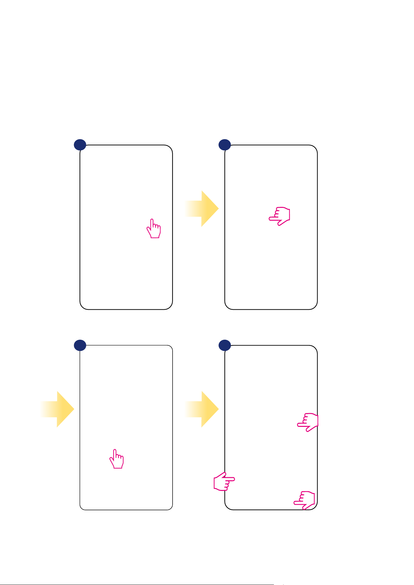
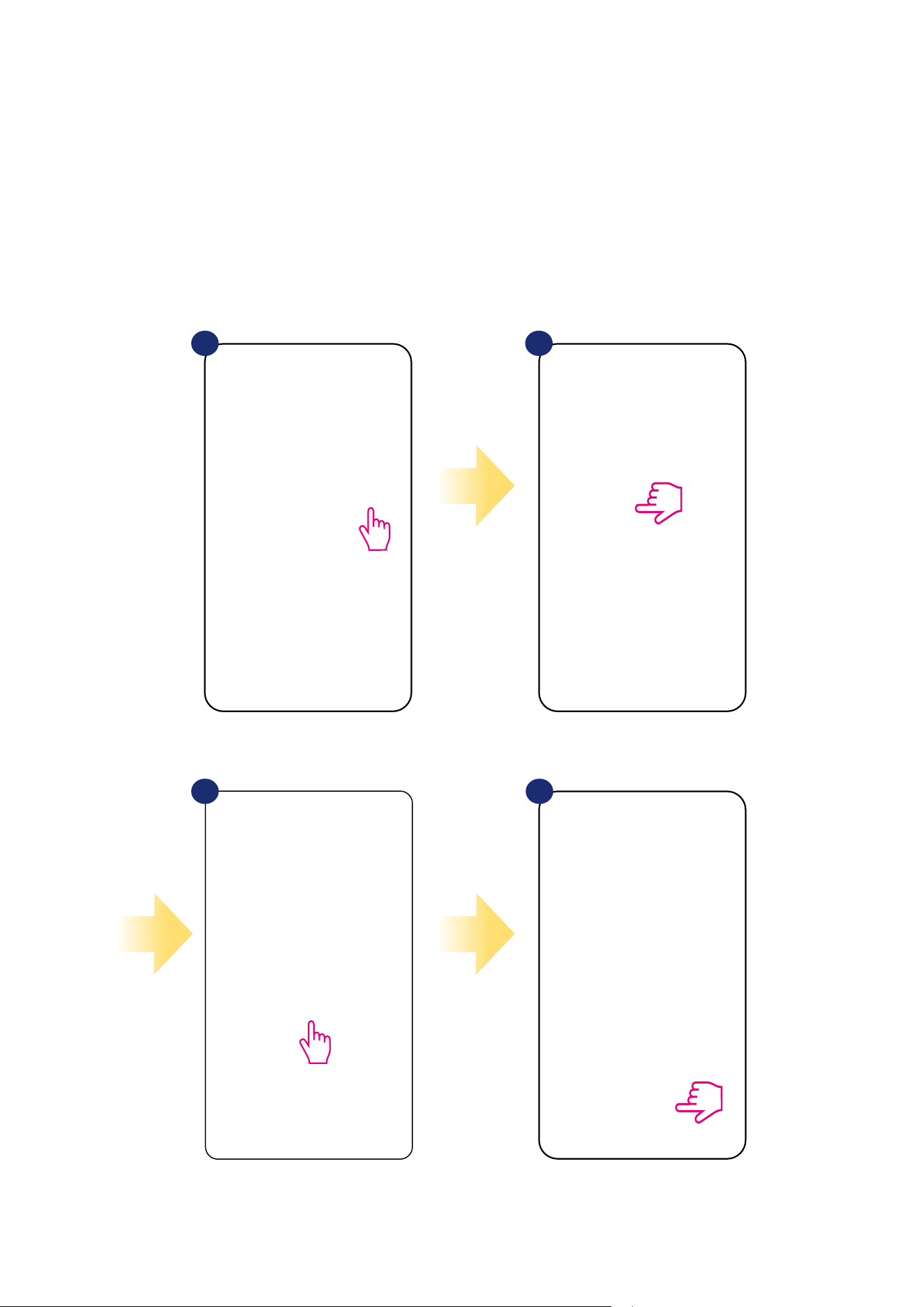
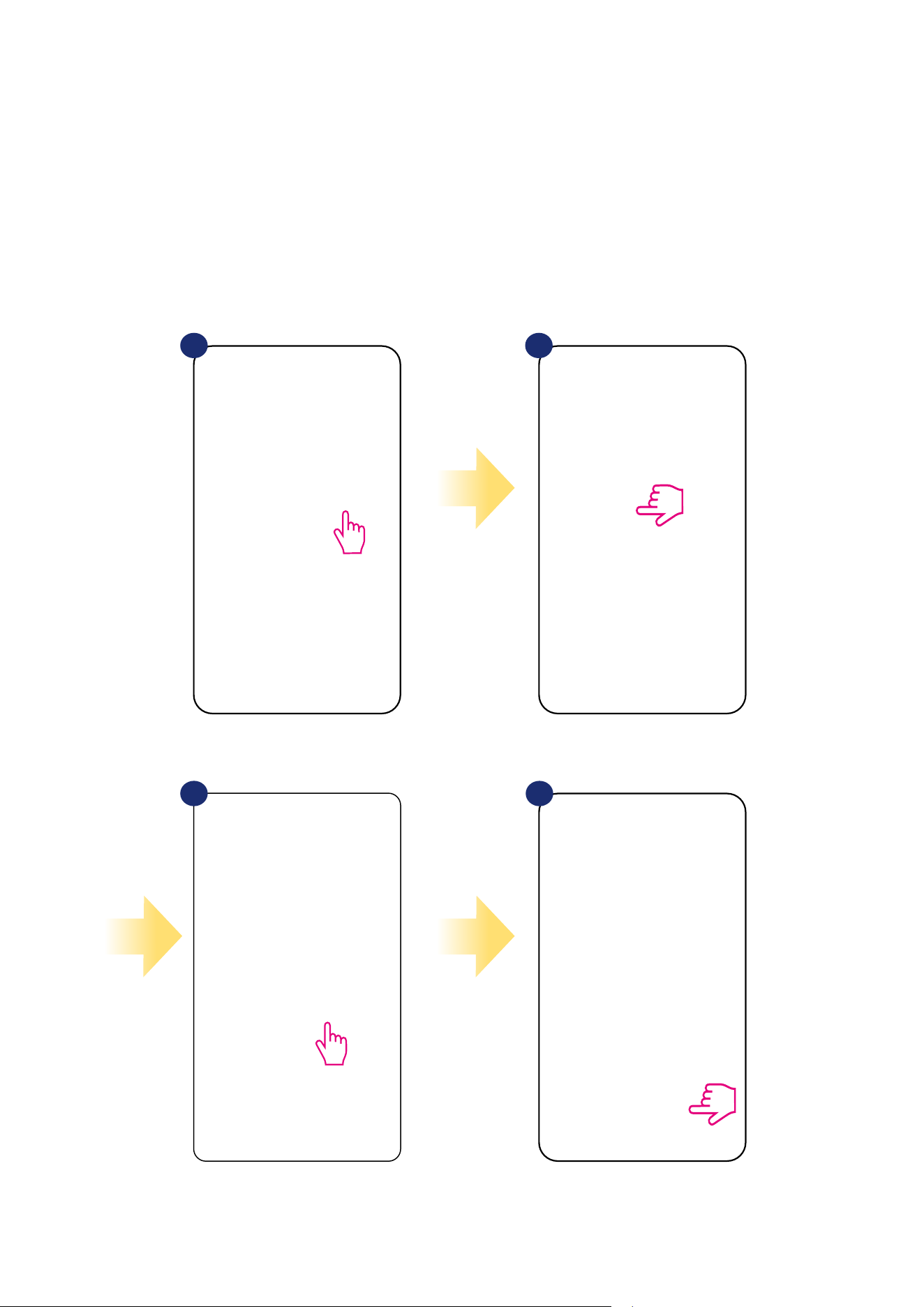
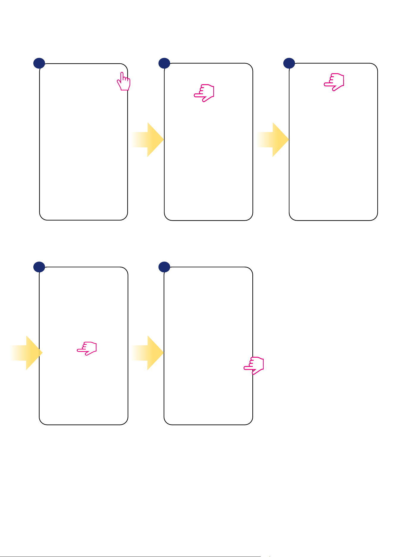
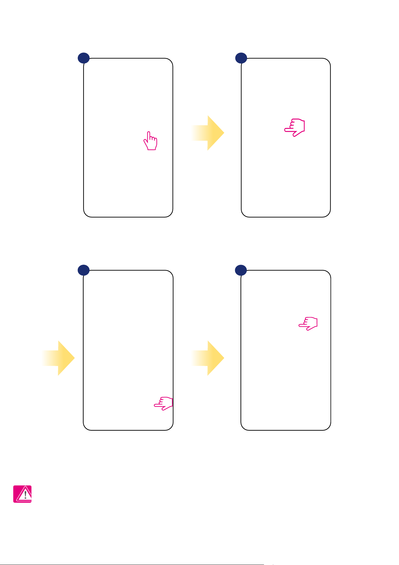
4.3 First power up sequence, language choice and preparing to the pair process
After that, thermostat will automatically power
up and start boot sequence...
Set your thermostat for underoor
heating or radiator heating by
„ ” or „ ” buttons.
Then conrm by button.
...it will display all icons...
...then thermostat will display the
software version.
To power on the thermostat you have
to connect it to the 230V power supply
then...
3
2
1
5
4
11
SALUS
Smart Home
GET IT ON
Download on the
3
2
5. Installation by SALUS Smart Home application (ONLINE MODE)
5.1 General informations about SALUS Smart Home application
Thanks to UGE600 Universal Gateway and SALUS Smart Home app system allows you to remote control of your heating system in any place you are
in the moment by smartphone, tablet or computer with Internet connection. Then you have also access to advanced functions of VS10WRF/VS10BRF
thermostat. You can also create OneTouch rules to customize system to your needs.
1
First make sure that you have downloaded the Salus Smart Home App from the Google Play or App
Store. You will need to follow a few easy steps to create an account and then link your thermostat to the
Universal Gateway and to the App.
You can also access the web version on:
http://eu.salusconnect.io/
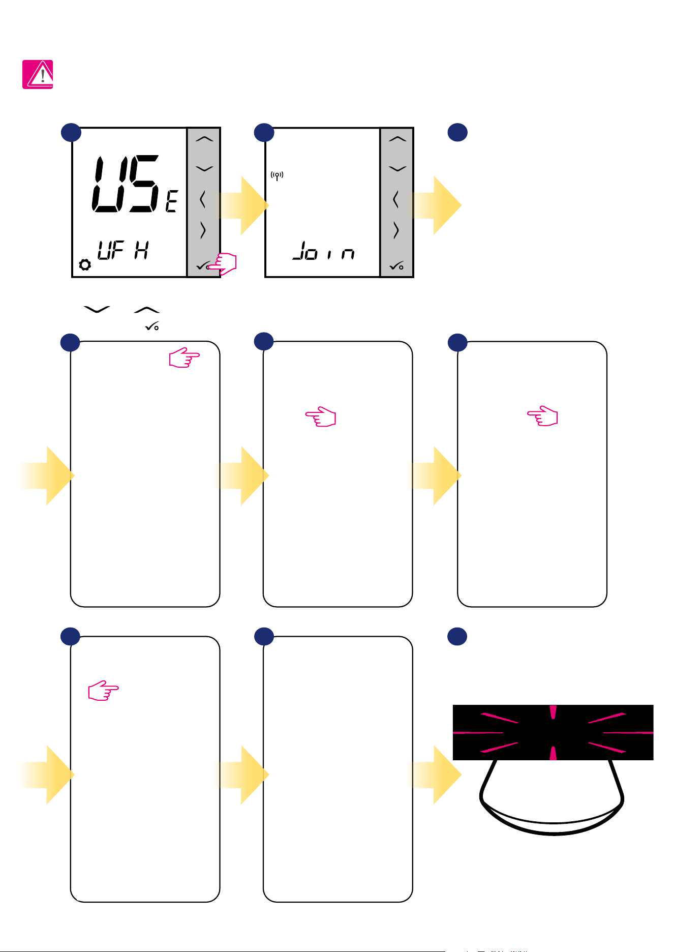
To begin the pairing process the Gateway should be plugged into the power supply and connected to the
Internet. Also, make sure that the UGE600 is added to your Salus Smart Home App. For the installation of
the Universal Gateway, please refer to the UGE600 manual on salus-manuals.com
Make sure that your UGE600 Universal Gateway is added to the App.
The LED of the Gateway should be steady blue. Then go to VS10WRF/
VS10BRF thermostat and begin paring process with the UGE600 and
add it to the App.
12
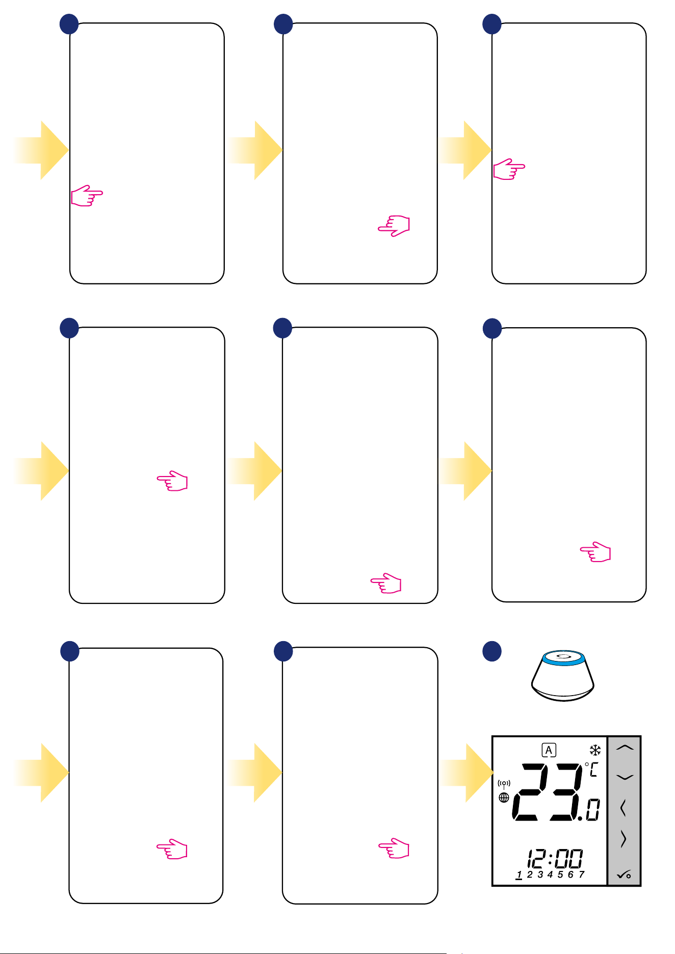
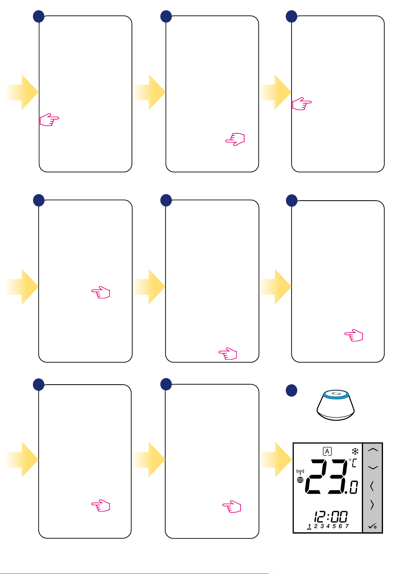
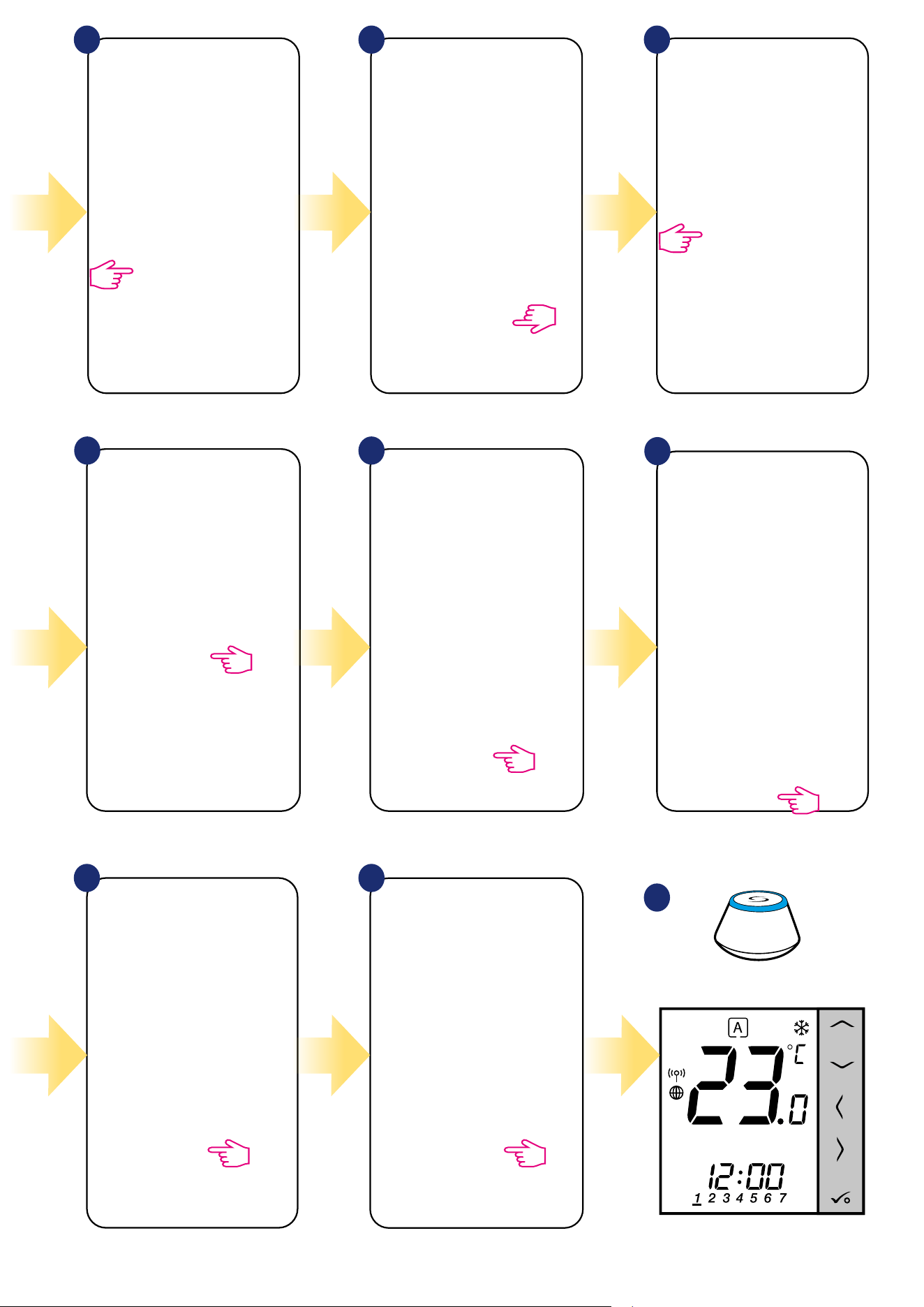
5.2.1 Pairing with underoor heating wiring centre (KL08RF/Control Box)
5.2 Conguration as a programmable thermostat
5
64
SALUS
SmartHome
Go to SALUS Smart Home app.
3
Now thermostat is looking for the
signal from the coordinator...
Open main menu. Select „Settings”. Now enter to the „Setup Equipment”.
Press „Scan for equipment” button.
7 8
App has started scanning...
1
2
For easier installation, please make sure you have already added underoor heating wiring centre (KL08RF/Control Box) to your ZigBee network (please
refer to the underoor heating wiring centre manual instruction).
Please note:
Set your thermostat for underoor heating
by „ ” or „ ” buttons. Then
conrm by button.
9
...Gateway has started ashing red and
searching for the thermostat...
13
Thermostat is connected. Go to the
Smart Home app to congure it.
10
Select your thermostat and press
„Connect equipment” button.
Name your thermostat and go
„Next”...
Press gear icon.
11 12
13
14
15
Select option „Programmable
Thermostat”.
Now choose
„UFH Wiring Centre” option.
14
17 18
2119
Choose „No” if you want to set your
own schedule later or „Yes” if default
now.
After that thermostat will display
main screen.
You succesfully congured
VS10WRF/VS10BRF
thermostat with KL08RF Control Box.
Select the zone which you want attribute to
your thermostat.
Press „Finish” button to end the set
up process in the app.
20
3
Gateway stop ashing and turn to steady
blue color which means pair process has
been nished.
16
Select your KL08RF/Control Box
added before.
15
5.2.2 Pairing with wireless TRV radiator head
1
SALUS
SmartHome
Go to SALUS Smart Home app.
3
Now thermostat is looking for the
signal from the coordinator...
5
64
Open main menu. Select „Settings”. Now enter to the „Setup Equipment”.
Thermostat is connected. Go to the
Smart Home app to congure it.
Press „Scan for equipment” button.
7 8
App has started scanning...
2
For easier installation, please make sure you have already added wireless TRV radiator heads to your ZigBee network (please refer to the wireless TRV
radiator head manual instruction).
Please note:
Set your thermostat for radiators by
„ ” or „ ” buttons.
Then conrm by button.
9
...Gateway has started ashing red and
searching for the thermostat...
16
After that thermostat will display main screen.
You succesfully congured VS10WRF/VS10BRF
thermostat with Wireless TRV radiator head.
1817
13
14 15
16
Now choose Smart Radiator Control.
Select your TRV radiator
head from the list.
Choose „No” if you want to set your own
schedule later or „Yes” if default now.
Select your thermostat and press
„Connect equipment” button.
Name your thermostat and go
„Next”...
Press gear icon.
10 11 12
Select option „Programmable Thermostat”.
Press „Finish” button to end the set
up process in the app.
3
Gateway stop ashing and turn to steady blue
color which means pair process has been nished.
17
5.2.3 Pairing with Smart Plug SPE600
1
SALUS
SmartHome
Go to SALUS Smart Home app.
3
Now thermostat is looking for the
signal from the coordinator...
5
64
Open main menu. Select „Settings”. Now enter to the „Setup Equipment”.
Press „Scan for equipment” button.
7 8
App has started scanning...
2
For easier installation, please make sure you have already added Smart Plug SPE600 to your ZigBee network (please refer to the Smart Plug SPE600
manual instruction).
Please note:
Set your thermostat for underoor heating
by „ ” or „ ” buttons. Then
conrm by button.
Thermostat is connected. Go to the
Smart Home app to congure it.
9
...Gateway has started ashing red and
searching for the thermostat...
18
Select your thermostat and press
„Connect equipment” button.
Name your thermostat and go
„Next”...
Press gear icon.
10 11 12
17
16
Choose „No” if you want to set your own
schedule later or „Yes” if default now.
13
Now choose Smart Plug.
Select your Smart Plug from the list.
14
15
Select option „Programmable Thermostat”.
Press „Finish” button to end the set
up process in the app.
After that thermostat will display main screen.
You succesfully congured VS10WRF/VS10BRF
thermostat with Smart Plug SPE600.
18
3
Gateway stop ashing and turn to steady blue
color which means pair process has been nished.
19
5.2.4 Pairing with Smart Relay SR600
1
SALUS
SmartHome
Go to SALUS Smart Home app.
3
Now thermostat is looking for the
signal from the coordinator...
5
64
Open main menu.
Select „Settings”.
Now enter to the „Setup Equipment”.
Press „Scan for equipment” button.
7 8
App has started scanning...
2
For easier installation, please make sure you have already added Smart Relay SR600 to your ZigBee network (please refer to the Smart Relay SR600
manual instruction).
Please note:
Set your thermostat for underoor heating
by „ ” or „ ” buttons. Then
conrm by button.
Thermostat is connected. Go to the
Smart Home app to congure it.
9
...Gateway has started ashing red and
searching for the thermostat...
20
Select your thermostat and press
„Connect equipment” button.
Name your thermostat and go
„Next”...
Press gear icon.
10 11 12
17
16
Choose „No” if you want to set your own
schedule later or „Yes” if default now.
13
Now choose Smart Relay.
Select your Smart Relay from the list.
14
15
Select option „Programmable Thermostat”.
Press „Finish” button to end the set
up process in the app.
After that thermostat will display main screen.
You succesfully congured VS10WRF/VS10BRF
thermostat with Smart Relay SR600.
18
3
Gateway stop ashing and turn to steady blue
color which means pair process has been nished.
21
5.2.5 Pairing with RX10RF receiver
1
SALUS
SmartHome
Go to SALUS Smart Home app
3
Now thermostat is looking for the
signal from the coordinator...
5 64
Open main menu.
Select „Settings”.
Now enter to the „Setup Equipment”.
Press „Scan for equipment” button.
7 8
App has started scanning...
2
For easier installation, please make sure you have already added RX10RF receiver to your ZigBee network (please refer to the RX10RF receiver manual
instruction).
Please note:
Set your thermostat for underoor heating
by „ ” or „ ” buttons. Conrm
by button.
Thermostat is connected. Go to the
Smart Home app to congure it.
9
...Gateway has started ashing red and
searching for the thermostat...
22
Select your thermostat and press
„Connect equipment” button.
Name your thermostat and go
„Next”...
Press gear icon.
10 11 12
17
16
Choose „No” if you want to set your own
schedule later or „Yes” if default now.
13
Choose „More” to expand the menu.
Now choose Boiler Receiver. If RX10RF is set as
„RX1” then choose option „Boiler Receiver”. If as a
„RX2” then select „Room Extension Receiver”.
14
15
Select option „Programmable Thermostat”.
Press „Finish” button to end the set
up process in the app.
After that thermostat will display main screen.
You succesfully congured VS10WRF/VS10BRF
thermostat with RX10RF receiver.
18
3
Gateway stop ashing and turn to steady blue
color which means pair process has been nished.
23
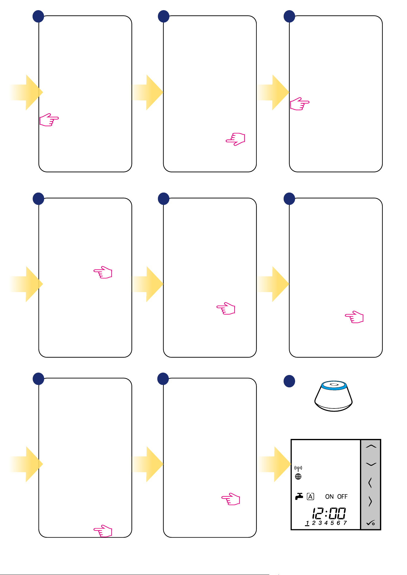
5.3 Conguration as a hot water timer
5.3.1 Pairing with Room Extension Receiver (RX2)
1
SALUS
SmartHome
Go to SALUS Smart Home app.
3
Now thermostat is looking for the
signal from the coordinator...
2
Set your thermostat for underoor heating
by „ ” or „ ” buttons. Conrm
by button.
5 64
Open main menu. Select „Settings”. Now enter to the „Setup Equipment”.
Press „Scan for equipment” button.
7 8
App has started scanning...
Thermostat is connected. Go to the
Smart Home app to congure it.
9
...Gateway has started ashing red and
searching for the thermostat...
PLEASE NOTE!
For easier installation, please make sure you have already added other devices to your ZigBee network, such as Underoor Heating Control Box (KL08RF)
or RX10RF.
24
Select your thermostat and press
„Connect equipment” button.
Name your thermostat and go
„Next”...
Press gear icon.
10 11 12
13
16 17
14
Press „More” to expand the menu.
Choose Room Extension Receiver. Press „Finish” button to end the set
up process in the app.
Select option „Hot Water Timer”.
Choose „More” to expand the menu.
15
After that thermostat will display main screen.
You succesfully congured VS10WRF/VS10BRF
thermostat as a hot water timer with RX10RF receiver.
18
3
Gateway stop ashing and turn to steady blue
color which means pair process has been nished.
25
6. OPERATING in ONLINE MODE (by app)
6.1 General informations
This section will show how to use your VS10WRF/VS10BRF thermostat with the UGE600 Universal Gateway and the Salus Smart Home App. In
order to do that, you will need a Salus UG600/UGE600 Universal Gateway, the Salus Smart Home App and Internet connection. Controlling your
thermostat via the App gives you a lot of freedom and the possibilities to manage the temperature in your house/oce remotely (Smart Home app is
available for Android/iOS mobile devices or Internet browser).
6.2 App icons description
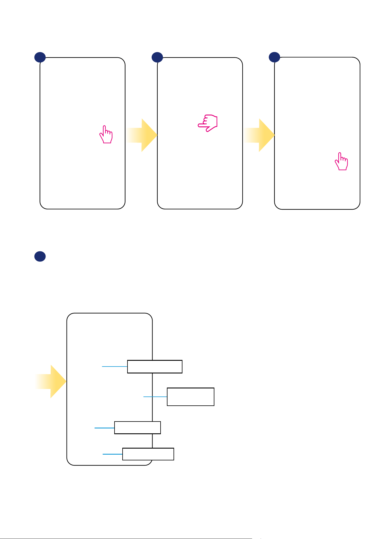
6.2.1 Programmable thermostat
Menu view of VS10WRF/VS10BRF thermostat set as a programmable thermostat in SALUS SmartHome application:
Thermostat mode
selection
Thermostat Heat/Cool mode indicator
Setpoint temperature slider
Thermostat name change tool
Thermostat locking/unlocking function
Pin/Unpin thermostat to/from
main application dashboard
Additional thermostat settings
(including advanced installer parameters)
Icons of devices like
window / door sensors
(OS600/SW600), Smart Plug
(SPE600) and SR600 smart
relay. You can see them
only when these devices are
paired with system.
Through these icons
you can pair VS10WRF/
VS10BRF thermostat fast
with selected device.
Room temperature
Identication tool
Thermostat name
Setpoint temperature
26
Menu view of VS10WRF/VS10BRF thermostat set as a Hot Water Timer in SALUS SmartHome application:
Thermostat name change tool
Thermostat locking/unlocking function
Pin/Unpin thermostat to/from
main application dashboard
Additional thermostat settings
(including advanced installer parameters)
Icons of devices like
window / door sensors
(OS600/SW600), Smart Plug
(SPE600) and SR600 smart
relay. You can see them only
when these devices are
paired with system.
Through these icons
you can pair VS10WRF/
VS10BRF thermostat fast
with selected device.
Hot Water Timer work mode
selection tool.
- Turned ON
- AUTO mode (schedule)
- Turned OFF
- Temporarily ON mode
Identication tool
Thermostat name
6.2.2 Hot Water Timer
27
6.3 Change thermostat name (pencil icon)
Name your termostat and
conrm it by „Save” button.
Click on the pencil icon.
Select the thermostat in
the main app menu.
1 2
3 4
Press the thermostat’s name.
28
6.4 Work as a programmable thermostat
6.4.1 Setpoint temperature change
You can change the setpoint by sliding the cursor to left/right on your App. On your App screen, the setpoint temperature is the number displayed in a
larger font.
Select the thermostat in
the main app menu.
1 2
3 4
Old setpoint value.
New setpoint value.
Thermostat has started heating
(ame icon changed colour from
white to orange).
29
6.4.2 Heat/Cool mode change (KL08RF connection)
VS10WRF/VS10BRF thermostat could be a heating device or cooling device. Default thermostat is set for heating. To set cool mode you have to
insert the jumper into „CO” terminal on KL08RF side. Look at the instructions below:
On the thermostat display you
will see „snowake” icon.
When thermostat is calling
for heating then ame icon is
displayed.
In the application you will see blue thermostat tile
with „snowake” icon when cooling mode is on.
1 2
When there is jumper at „CO” terminal KL08RF is
automatically working in cooling mode.
3
1 2 3
When there is no jumper at „CO” terminal KL08RF
is automatically working in heating mode.
In the application you will see orange thermostat
tile with „Flame” icon when heating mode is on.
COOLING MODE:
HEATING MODE:
30
Additionally, you can choose to set the Default schedule that already exist in the App, or to modify it according to your preferences. The schedule is
displayed at the bottom of screen of your App on the selected thermostat. You can activate the schedule by pressing the Follow Schedule icon on your App.
Once activated, the calendar icon will appear on your screen.
The VS10WRF/VS10BRF thermostat gives you the possibility to programm schedule. You can add up to 6 programs during one day by selecting the
program’s start time and temperature. You can choose from 3 dierent schedule congurations:
• Separate schedule for working days (Mo-Fri) and weekend (Sat-Sun)
• Individual schedules for each day at the week
• One schedule for whole week
Choose „Follow Schedule”
work mode.
6.4.3 Thermostat modes
6.4.3.1 Schedule mode
To activate schedule mode:
Select thermostat in the
main app menu.
Click on the work mode icon.
1 2
3
When Schedule Mode is activated
then
frame will move on the „A”
letter.
4
31
Select thermostat in the
main app menu.
1 2 3
Scroll down and press pencil button.
As you can see there is default
schedule. You can delete all default
intervals by button.
Choose for which days you want to
program your schedule:
• Working Week / MON - FRI and SAT + SUN
• Home most of the time / MON - SUN
• Daily
After days period selection use
„Add interval” option to add your
intervals to the schedule.
Then add a start time and
temperature setpoint, after all -
conrm by pressing „Add” button.
4 5 6
TO SET THE SCHEDULE IN THE APP:
Press thermostat’s name.
Please note:
You can add as many intervals as you wish by repeating the procedure described from steps 3 to 6. The procedure is the same for all 3 schedule
congurations. You can customize the programs on the thermostat in any way you want.
32
After you’ve added all the intervals,
tap „Save” to save it. Your schedule
has been saved and set.
7
10
8 9
PLEASE NOTE: To delete any interval in the schedule just use
button next to selected interval.
ADDITIONALLY: You can
duplicate the same schedule for
other thermostat’s. Click on the
„Duplicate schedule” option.
Select thermostat for which you
want to duplicate the schedule.
Now app is saving your choice and
after it you will have the same
schedule for thermostat’s you’ve
selected.
Please note:
When thermostat has no schedule (or it has been deleted) then it maintains a constant temperature 21 °C (in „Follow Schedule” mode).
33
To set default schedule use „Default schedule”
button. It will remove all current intervals and
it will set default schedule.
4
Select thermostat in the
main app menu.
1 2
3
Scroll down and press pencil icon.
TO SET DEFAULT SCHEDULE:
Press thermostat’s name.
34
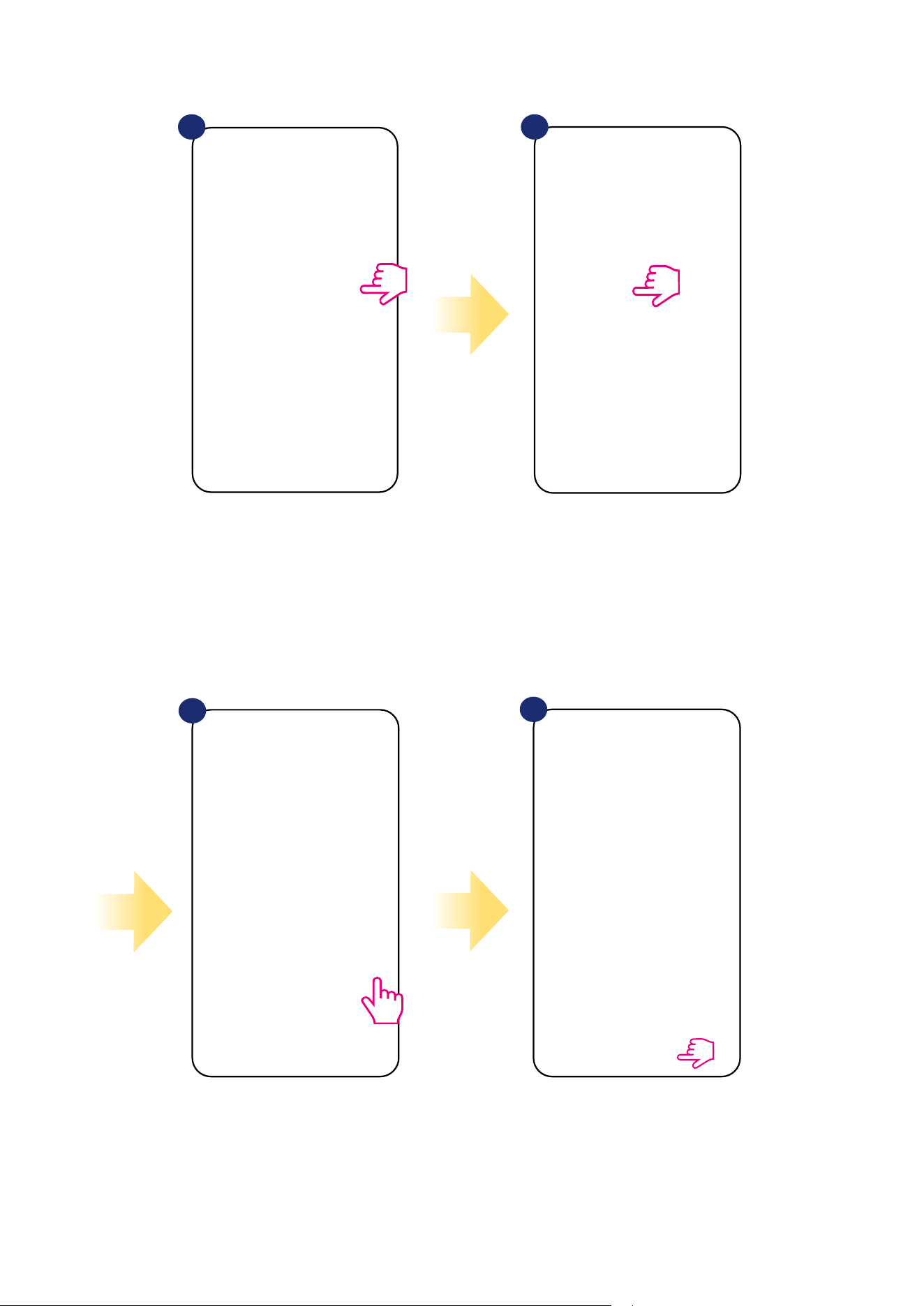
6.4.3.3 Manual mode
If the thermostat follows a schedule or is in frost protection mode, user can change the operating mode to the manual mode. In manual mode
thermostat will maintain setpoint temperature until user will manually change it to a new value or select a new operating mode. When thermostat works
in manual mode, the hand icon will be displayed in the app screen.
Click thermostat’s work modes icon. Select „Permanent Hold” mode. Hand icon conrms that thermostat
is in manual mode.
1 2 2
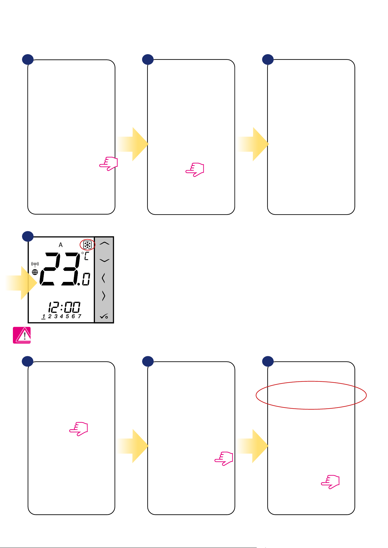
6.4.3.2 Temporary override mode
Temporary override mode means manual temperature change during active schedule mode:
NOTE: Temporary override mode will be maintained until next program will come, as it has been set in the schedule.
When „Follow schedule” mode is active,
use slider to set new setpoint
temperature.
When you have overwritten the temperature
then hand icon will appear next to calendar
which means that temporary override mode is
working until next schedule program.
When you overwrote schedule’s setpoint
temperature then on the thermostat’s
display you will see
the hand icon.
31 2
35
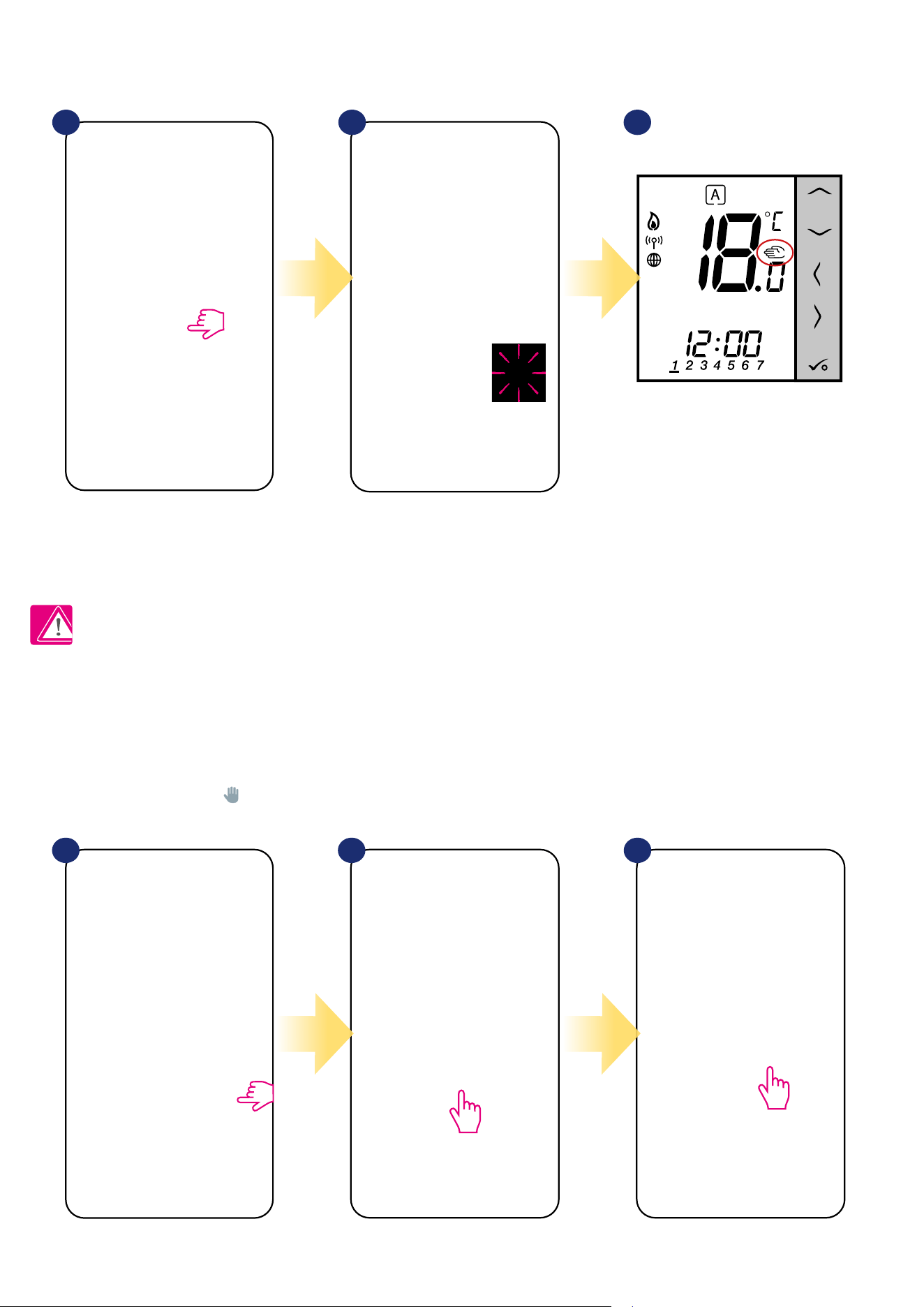
6.4.3.4 Frost protection
In Frost protection mode the thermostat is displaying actual room temperature and maintain „frost protection” setpoint temperature specied in
thermostat settings (please refer to chapter 8.3). When thermostat works in Frost protection mode then you have no possibilities to change
temperature setpoint. To activate Frost protection mode online please followe steps below:
Note: When the thermostat exits frost protection mode, previous mode will be restored.
PLEASE NOTE: You can change frost protection mode temperature setpoint from the application level (D08 parameter). Follow steps below:
Press thermostat’s work modes icon.
Click in the thermostat’s name. Select thermostat’s settings. Set frost setpoint temperature and
conrm by „Save” button.
Select „OFF” mode.
Also on the thermostat’s display you
can see that frost protection mode is
activated by „Snow” icon.
Thermostat is in frost protection mode.
1
1 2 3
2 3
4
36
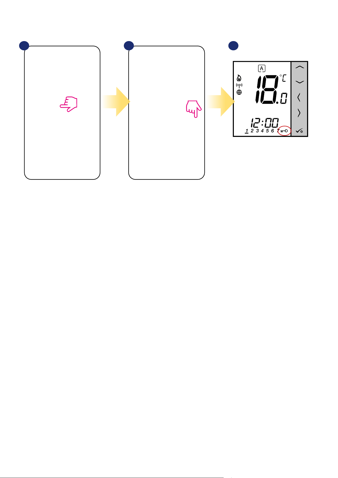
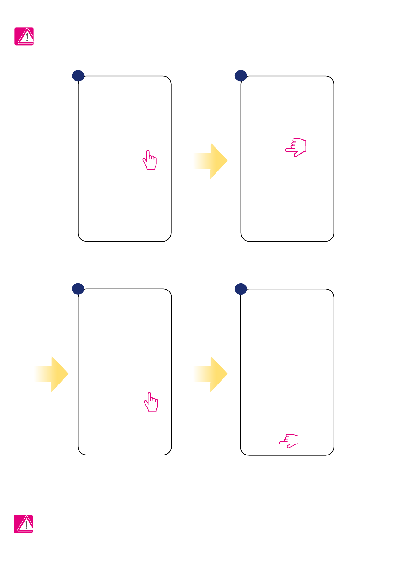
6.4.4 Key lock function
You can lock/unlock buttons in your thermostat by application.
When buttons are locked then also you
can see on the thermostat display „key”
icon.
Click on the „padlock” icon to
lock/unlock thermostat buttons.
1
2 3
Click in the thermostat’s name.
37
6.4.5 Compatibility with window/door sensor OS600 / SW600
VS10WRF/VS10BRF thermostat paired with window/door sensor OS600/SW600 allows to create
OneTouch rules when window/door is opened or closed. If thermostat will receive information from
window/door sensor (that window has been opened for example) then OneTouch rule will turn o heating
until window close. If you want to have acces to this function then rst you have to add window/door sensor
OS600 or SW600 (please refer to the OS600 or SW600 manual instruction).
To pair window/door sensor OS600/SW600 with VS10WRF/VS10BRF thermostat please follow steps below:
Mark sensors which you want to link together with the
thermostat. You can additionaly lock buttons on thermostat
when window is opened by marking option above.
Press „Save” button to nish pair process...
1 2
3
4
Select the thermostat in
the main app menu.
Press thermostat’s name.
Choose the window icon.
38
6.4.6 Compatibility with Smart Plug SPE600
VS10WRF/VS10BRF thermostat paired with SPE600 Smart Plug allows to turn on/o any electric
device eg. pump, radiator or valve with actuator. When thermostat starts heating then plug will turn on
device (or turn o when there is no need to heat). If you want to have acces to this function then rst
you have to add SPE600 Smart Plug to the SALUS SmartHome system (please refer to the SPE600
manual instruction).
To pair SPE600 Smart Plug with VS10WRF/VS10BRF thermostat please follow steps below:
Choose plugs which you want to add to the
thermostat. Press „Save” button to nish pair
process...
Choose the plug icon.
1 2
Select the thermostat in
the main app menu.
3 4
Press thermostat’s name.
39
6.4.7 Compatibility with Smart Relay SR600
VS10WRF/VS10BRF thermostat paired with Smart Relay SR600 allows to wireless control of eg. radiator,
pump, boiler. When thermostat start heating then SR600 Smart Relay will turn on device (or turn o
when there is no need to heat). If you want to have acces to this function then rst you have to add SR600
Smart Relay to the SALUS SmartHome system (please refer to the SR600 manual instruction).
To pair SR600 Smart Relay with VS10WRF/VS10BRF thermostat please follow steps below:
Choose SR600 relays which you want to add
to the thermostat. Press „Save” button to
nish pair process...
Press the relay icon.
1 2
Select the thermostat in
the main app menu.
3
4
Press thermostat’s name.
40
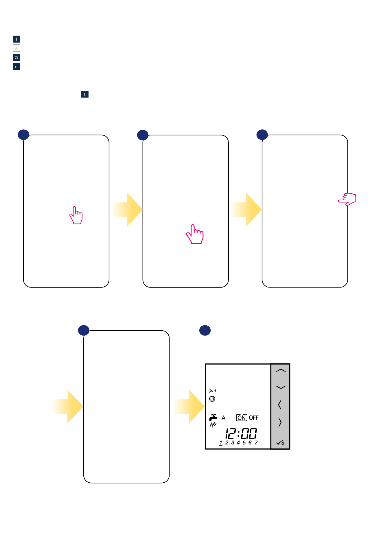
1
3
4 5
2
Select the thermostat in the main
app menu.
Close thermostat’s tile.
Now you can see thermostat’s tile in
orange colour which means it has
started call for heating.
Also on thermostat’s display you can
see the current mode.
Turn ON the hot water timer.
6.5 Work as a hot water timer (work modes)
6.5.1 Turned ON mode -
Thermostat is manually turned on and work as long as you change this mode to another or switch it o. To set this mode on, please follow steps below:
VS10WRF/VS10BRF thermostat has 4 work modes as a hot water timer:
- Turned ON - (thermostat is manually turned on and work as long as you change this mode to another or switch it o),
- AUTO mode - (thermostat is following schedule which you programmed - look at chapter 6.4.3.1 Schedule mode, page 30),
- Turned OFF - (thermostat is manually turned o as long as you select other mode),
- Temporarily ON mode - (you can fast set the water heating time in this mode in limited hour period (from 1 to 4 hours)).
41
6.5.2 AUTO mode -
Thermostat is following schedule which you programmed - look at chapter 6.4.3.1 Schedule mode, page 29. To set this mode on, please follow steps below:
1 3
4 5
2
Select the thermostat in the main
app menu.
Close thermostat’s tile.
Thermostat is in auto mode
(it is following schedule).
Select AUTO mode.
Also on thermostat’s display you can
see the current mode.
42
Thermostat is manually turned o as long as you select other mode. To set this mode on, please follow steps below:
6.5.3 Turned OFF mode -
1 3
4 5
2
Select the thermostat in the main
app menu.
Close thermostat’s tile.
Thermostat is turned o.
Tile is in green colour.
Turn OFF thermostat.
Also on thermostat’s display you can
see the current mode.
43
6.5.4 Temporarily ON mode -
1
4 5 6
2 3
Select the thermostat in the main
app menu.
Close thermostat’s tile. Thermostat is in temporarily mode
(for 4 hours in this case). You can
turn it o by choosing other mode.
Select temporarily mode (B letter). Choose hour value.
You can fast set the water heating time in this mode in limited hour period (from 1 to 4 hours). To set this mode on, please follow steps below:
Also on thermostat’s display you can
see the current mode.
44
6.6 Identication mode
Identication mode can be useful when we are pairing more than one device in one moment and we don’t know which device is which. Beyond, if our
system include more that one UGE600 Universal Gateway then we can easily identify which device is paired with which gateway.
In the Identication mode thermostat’s
display will start ashing „Id” information for
10 minutes.
You can also identify your device during thermostat’s pairing process:
4
Use the magnifying glass icon.
Click on the magnifying glass icon.
1 2
Select the thermostat in
the main app menu.
3
Press thermostat’s name.
45
6.7 Pinning/unpinning thermostat to/from application dashboard
To pin/unpin thermostat from dashboard in Smart Home application please follow steps below:
1 2 3
Open main menu in the app. Select equipment. Select All equipment option.
Select your VS10WRF/VS10BRF
thermostat.
Press on the „Pin” icon to pin/unpin
thermostat to/from the app dashboard.
4 5
46
User settings of VS10WRF/VS10BRF thermostat determine basic thermostat parameters. Please see below how to enter those settings:
6.8 User settings (basic settings)
Select the thermostat in
the main app menu.
Select thermostat’s settings.
1 2
3
Press thermostat’s name.
Select the hour format
for the thermostat.
Set the frost protection
setpoint temperature.
Turn on or turn o the
display on the thermostat.
Installer (administration)
settings.
BASIC SETTINGS:
4
Scroll down to the settings section.
47
6.9 Admin settings (installer parameters)
PLEASE NOTE: Admin settings are mainly for qualied installers or knowledgeable users.
Scroll down to enter
„Admin settings”.
Select the thermostat in
the main app menu.
Select thermostat’s settings.
1 2
3
4
Press thermostat’s name.
All service parameters with detailed admin settings are described on page 74!
Please Note:
48
6.10 OneTouch rules (add/edit)
OneTouch - function that distinguish SALUS Smart Home system in terms of functionality. OneTouch rules are pre-congured set of actions dened
in the interface easy in use. You can switch it on or o anytime. OneTouch informs thermostat or other device how it has to work according to pre-set
settings. In application are 4 pre-dened OneTouch rules:
• Party Mode - set thermostat temperature to 21 °C for 2 hours
• Comfort Temperature - set thermostat temperature to 21°C
• Frost Protection Mode - set thermostat to the Frost Mode (temperature setpoint can be set in the user settings) - 5°C by default
• Holiday Mode - set thermostat to the Holiday Mode
To activate OneTouch rules please follow steps below (example on Party Mode):
Party Mode has been activated.
You can check how it works by
pressing „Run now” button.
Choose „Party Mode” as a one
of the built-in OneTouch rules.
Click „Add OneTouch” to add it.
Select thermostats which you
want to congure with this rule.
Press „Apply” to conrm.
1 2 3
Open main menu in the app. Select equipment. Select OneTouch option.
4 5 6
49
1
4 5 6
2 3
Open main menu in the app. Select equipment. Select OneTouch option.
You can also create your own OneTouch rule. As an example we will create OneTouch rule which activates „send me a notication” action under
„temperature is below 10 °C” condition. Please look at the steps below how to set this OneTouch rule.
Press „Add a AND OneTouch” button. Enter OneTouch rule name. At this step choose condition which
have to be fullll in order to activate
the rule.
50
Select which thermostat you want to
link up with your OneTouch rule.
Select „DO THIS” option to create
OneTouch rule action.
Choose e-mail or SMS
notication and enter the message
content. Conrm by pressing „Set”
button.
To nish OneTouch rule creation press
„Save” button.
Choose the condition details for your
thermostat. In this case select
„Temperature Below” option.
Enter a temperature setpoint trigger
for your OneTouch rule. Press „Set”
button to conrm.
7
10 11 12
8 9
51
OneTouch rule is now activated. In this
example SMS message will be send to
the user.
...and press it’s button.
As an option OneTouch rule tile can be
pinned to the dashboard.
Newly created OneTouch rule tile can be
found under OneTouch main menu...
... and on your dashboard.
To force OneTouch rule activation select
it tile...
13
17 18
14 15
16
Please note: SMS notications will be send to the user only if they are activated in the OneTouch settings and UGE600 Universal Gateway is
connected to the Internet.
52
6.11 Error codes (exclamation mark in app)
If there is any error in the Smart Home system which relates to the devices performance or functionality then the Smart Home app will inform user about
it by a red exclamation mark in the upper menu. Please look at the example below:
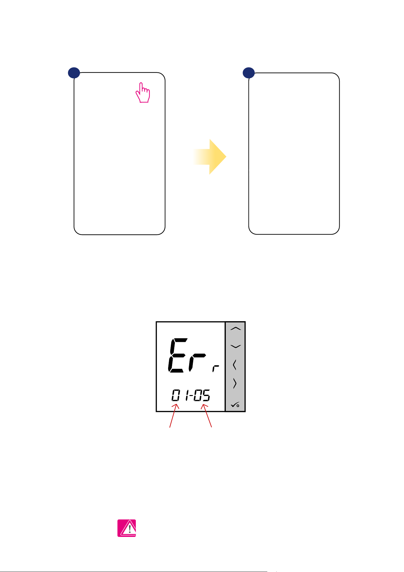
Errors are visible also on the thermostat’s LCD display.
ERR 01-03 (Floor Sensor Defect) means that there is a break in the circuit of the temperature sensor plugged
into the S1 / S2 contacts of the thermostat or the sensor has been activated and not connected to the thermostat.
When problem has been solved (sensor change or re-connection in this case) -
exclamation mark will disappear in application and thermostat will stop ashing error.
Full list of errors is in chapter 11.
1 2
Press the exclamation mark button. All current errors are displayed.
Number of errors Error code
53
6.12 Wireless signal strength test
Each wireless device has a limited range. Beyond distance there are many more elements which could aect on. For example - concrete walls, other
wireless network interferences, wooden walls, reinforced concrete ceilings, metal construction elements, pillars, aluminium foil for underoor heating etc.
Smart Home system has built-in function which allows to check wireless signal quality. If you want to check your system connectivity
and signal’s strength please follow steps below:
Signal quality is expressed in decibel units (db). Compare your value with scale below:
-50db to 0db - very good quality signal
-75db to -50db - good quality signal
-85db to -75db - low quality signal
-95db to -85db - bad quality signal, make wireless connection nearly impossible
PLEASE NOTE: Every Smart Home system device which is powered 230VAC is also working as a signal repeater of ZigBee network. If system is
based on battery devices there could be a need to use repeaters like Salus RE600, Salus RE10RF or any other device of Salus Smart Home series
which is powered by 230V AC.
Press the gear icon in upper right
corner of the background image.
Select „Scan my home” option. Here you can check wireless
signal quality of given devices.
1 2 3
54
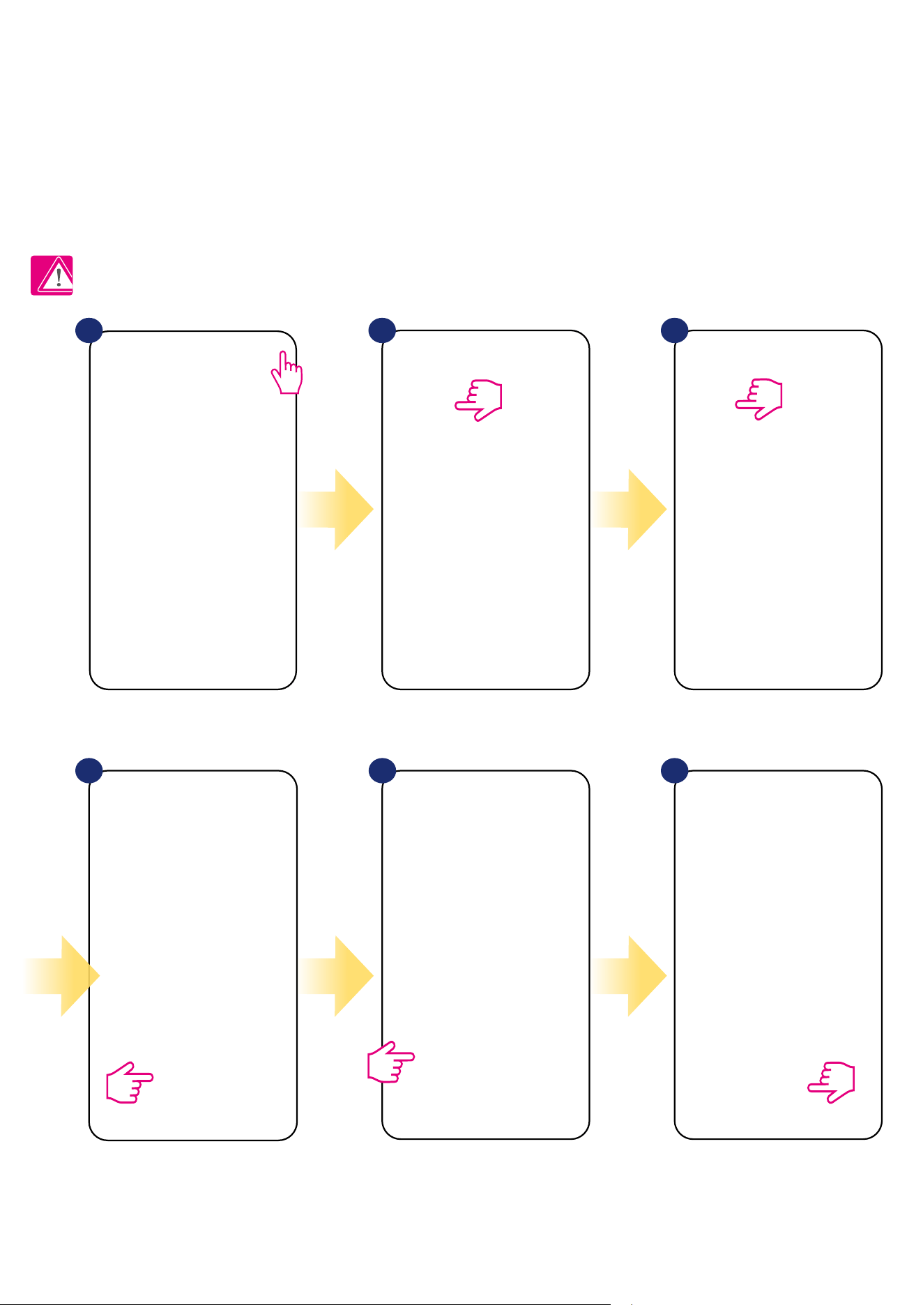
6.13 Factory reset (removing thermostat from the app and ZigBee network)
To make thermostat factory reset and remove it from the ZigBee network please follow steps below:
NOTE: Factory reset function removes thermostat from the ZigBee network. This means that thermostat is not visible anymore in the „My equipment” list.
At the very bottom of
thermostat’s menu choose
„Remove” option.
Press „Delete” button to remove
your thermostat from the app
and conrm factory reset.
1 2
Select the thermostat in
the main app menu.
3
4
Press thermostat’s name.
55
At the very bottom of thermostat’s
menu choose „Remove” option.
Press „Delete” button to remove your
thermostat from the app and conrm
factory reset.
Select the thermostat in
the main app menu.
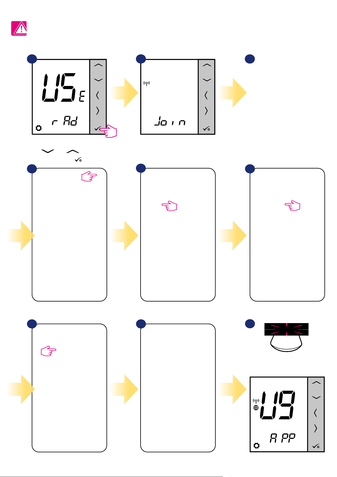
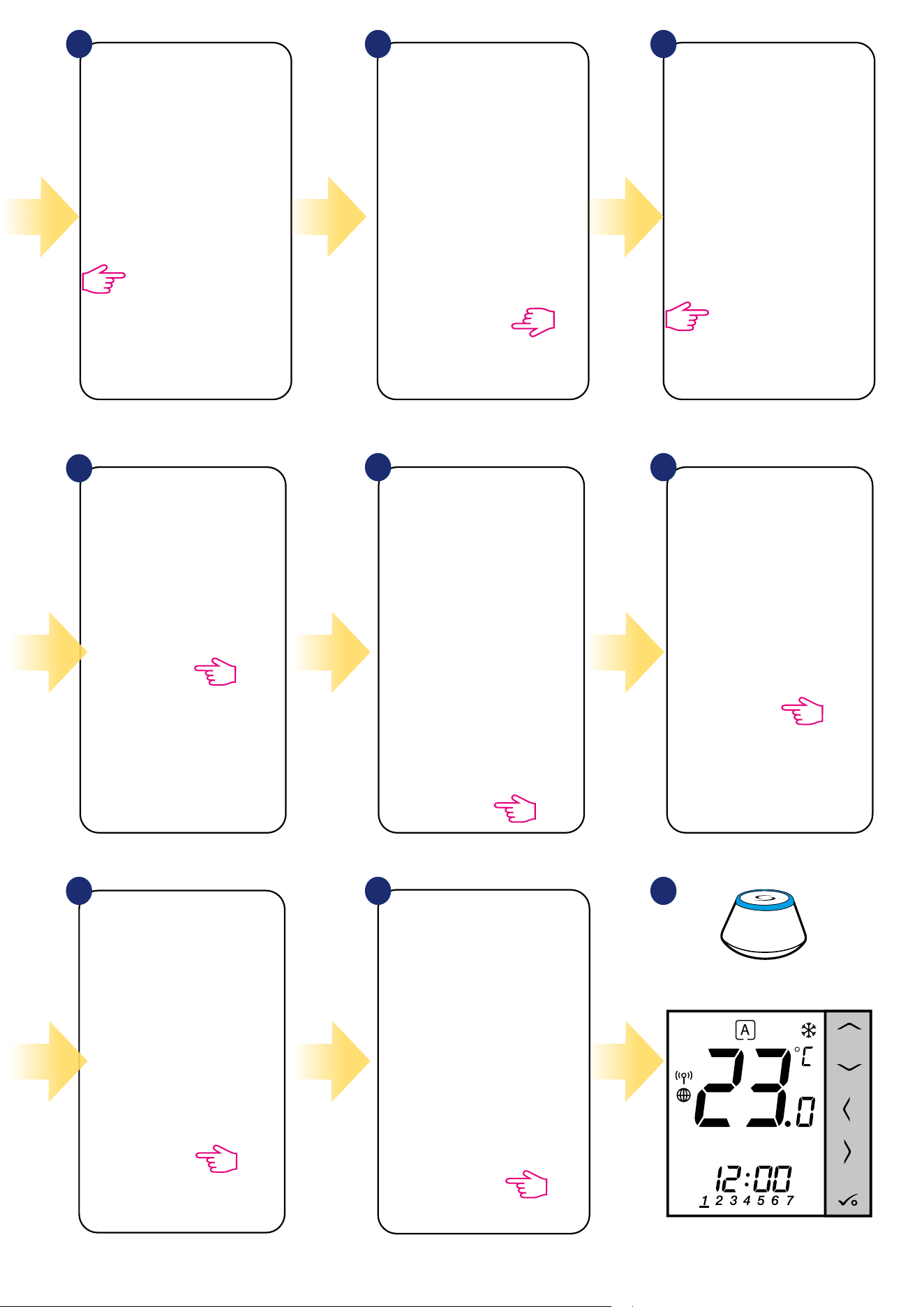
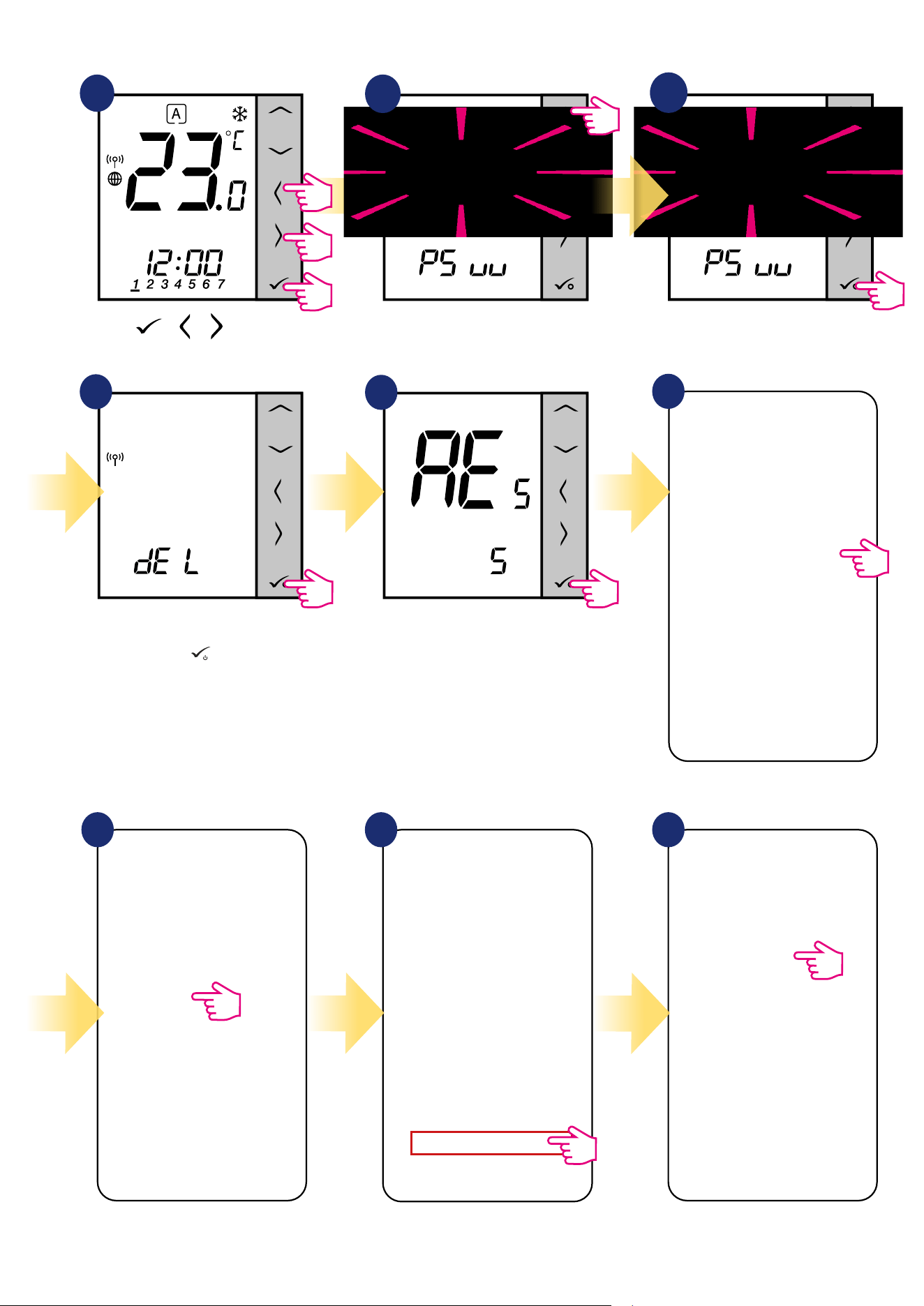
You can also do factory reset from the thermostat directly. It will also remove your thermostat from the Zigbee network but you still will be able
to see thermostat’s tile. After factory reset thermostat tile will change to dark grey colour.
1
2
3
4
5
Wait few moments to nish factory
reset procedure. Now you can
remove thermostat from the app.
Go to the Admin Settings.
Press buttons for 5
seconds to enter the installer mode.
Choose „Factory Reset” option.
Select „del” and conrm choice by
pressing
button
.
6
7 8 9
Press thermostat’s name.
5 sec.
5 sec.
5 sec.
+ +
56
7. Installation in OFFLINE MODE without SALUS SmartHome application
7.1 General informations
In OFFLINE mode (without application), you can use the UGE600 Universal Gateway or CO10RF coordinator to congure the system. Please note
that you cannot use both devices at the same time. Before installing the system you have to decide:
- to create a network using the UGE600 Universal Gateway (you can connect it to the Internet in the future)
- to create a network using the CO10RF coordinator (you can’t connect it to the Internet)
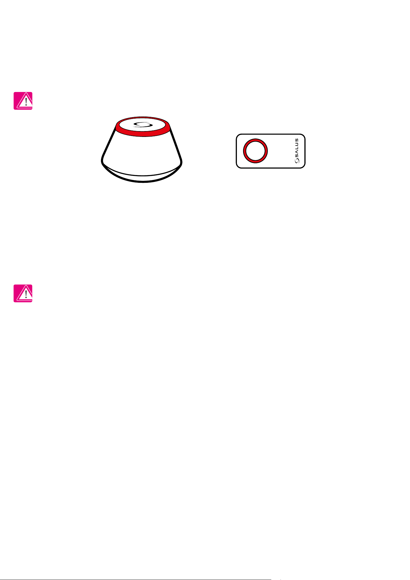
REMEMBER! The UGE600 Universal Gateway and CO10RF coordinator are two dierent devices.
Each device creates and operates it’s own network.
Universal Gateway - - CO10RF Coordinator
Please note! If your system has been installed in the OFFLINE mode using the UGE600 Universal Gateway and then connected to the Internet,
all devices should be found in the SALUS Smart Home application (using „Scan for equipment” button). All devices found in the application don’t
need to be recongured, because all settings are automatically copied from the gateway.
Please note! If your system was created using the CO10RF coordinator and you would like to control the devices via the Internet, then all
devices should be reinstalled using the UGE600 Universal Gateway.
CO10RF Coordinator
You can use standard ZigBee network coordinator to install and use your
devices.
NOTE: CO10RF Coordinator is included in the set with the KL08RF
Control Box.
Universal Gateway is
NOT CONNECTED TO THE INTERNET
You can use your devices locally without the Smart Home App. Gateway
works in this mode as standard ZigBee coordinator.
KL08RF - Wiring Centre for 8-zone
underoor heating (UFH).
+ extension KL04RF
TRV
(Thermostatic Radiator Valve)
- with wireless communication.
RX10RF
receiver
57
7.2 Pairing with underoor heating wiring centre (KL08RF/Control Box)
7.2.1 Available operation modes
CASE 1
GROUP 1 - consists of 4 thermostats (in addition, more thermostats can be assigned to a group in further zones located in the wiring centre). Managed by
1 weekly, programmable thermostat, congured as a MASTER (group 1), e.g. VS10WRF. The other 3 thermostats are daily, non-programmable, congured
as a SLAVE (group 1), e.g. VS10WRF, VS20WRF or HTRS-RF(30). The MASTER thermostat can aect the SLAVE thermostats (VS10WRF, VS20WRF or
HTRS-RF(30)), which will follow the schedule set on the VS10WRF thermostat. Remember - if you want MASTER thermostat to control the SLAVE
thermostats, then all SLAVE thermostats have to be set to AUTO mode - . The VS10WRF thermostat is congured as a MASTER or SLAVE thermostat
during pairing with the KL08RF underoor heating wiring centre (see section 7.2.2).
GRUPA 2
Regulator programowany
VS10WRF (Master gr 1)
- zasilany 230V
Programowany regulator
VS20WRF - zasilany bateryjnie
Regulator grupowy
(Slave) VS20WRF
- zasilany bateryjnie
Regulator grupowy
(Slave) VS20WRF
- zasilany bateryjnie
Regulator grupowy
(Slave) VS10WRF
- zasilany 230V
Regulator grupowy
VS10WRF
- zasilany 230V
Regulator programowany
VS20WRF (Maste gr 2)
- zasilany bateryjnie
GRUPA 1
Regulator indywidualnej
strefy grzewczej
Zasilanie 230V AC
Przewód 1,5mm2,
Dostarcza instalator
VA
C
Rozdzielacz ogrzewania podłogowego
Moduł sterowania kotłem listwy KL08RF należy
podpiąć do kotła w miejsce zworki termostatu pokojowego.
NL
NL
Wyjście na czujnik punktu
rosy (opcjonalnie).
UWAGA: Przekaźnik modułu
sterowania pompy w listwie
KL08NSB jest beznapięciowy
- dlatego podłączając pompę
CO należy wykorzystać zewnętrzne
źródło zasilania pompy.
N
L
UWAGA: Przekaźnik modułu
sterowania pompy w listwie
KL08RF jest beznapięciowy
-dlatego podłączając pompę
CO należy wykorzystać
zewnętrzne źródło zasilania
pompy.
Przykład zastosowania regulatorów temperatury:
Do listwy KL08RF można podłączyć poniższe regulatory:
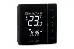
VS10WRF - Regulator podtynkowy, biały, zasilany 230V.
VS10BRF - Regulator podtynkowy, czarny, zasilany 230V.
VS20WRF - Regulator natynkowy, biały, zasilany bateryjnie (4xAAA)
VS20BRF - Regulator natynkowy, czarny, zasilany bateryjnie (4xAAA)
Powyższe regulatory mogą być stosowane wymiennie w różnych strefach.
Uwaga: Każde urządzenie w serii iT600RF, zasilane napięciem 230V jest
jednocześnie repeater'em sygnału (zwiększa zasięg sieci regulatorów)
GRUPA 2
Regulator programowany
VS10WRF (Master gr 1)
- zasilany 230V
Programowany regulator
VS20WRF - zasilany bateryjnie
Regulator grupowy
(Slave) VS20WRF
- zasilany bateryjnie
Regulator grupowy
(Slave) VS20WRF
- zasilany bateryjnie
Regulator grupowy
(Slave) VS10WRF
- zasilany 230V
Regulator grupowy
VS10WRF
- zasilany 230V
Regulator programowany
VS20WRF (Maste gr 2)
- zasilany bateryjnie
GRUPA 1
Regulator indywidualnej
strefy grzewczej
Zasilanie 230V AC
Przewód 1,5mm2,
Dostarcza instalator
VA
C
Rozdzielacz ogrzewania podłogowego
Moduł sterowania kotłem listwy KL08RF należy
podpiąć do kotła w miejsce zworki termostatu pokojowego.
NL
NL
Wyjście na czujnik punktu
rosy (opcjonalnie).
UWAGA: Przekaźnik modułu
sterowania pompy w listwie
KL08NSB jest beznapięciowy
- dlatego podłączając pompę
CO należy wykorzystać zewnętrzne
źródło zasilania pompy.
N
L
UWAGA: Przekaźnik modułu
sterowania pompy w listwie
KL08RF jest beznapięciowy
-dlatego podłączając pompę
CO należy wykorzystać
zewnętrzne źródło zasilania
pompy.
Przykład zastosowania regulatorów temperatury:
Do listwy KL08RF można podłączyć poniższe regulatory:
VS10WRF - Regulator podtynkowy, biały, zasilany 230V.
VS10BRF - Regulator podtynkowy, czarny, zasilany 230V.
VS20WRF - Regulator natynkowy, biały, zasilany bateryjnie (4xAAA)
VS20BRF - Regulator natynkowy, czarny, zasilany bateryjnie (4xAAA)
Powyższe regulatory mogą być stosowane wymiennie w różnych strefach.
Uwaga: Każde urządzenie w serii iT600RF, zasilane napięciem 230V jest
jednocześnie repeater'em sygnału (zwiększa zasięg sieci regulatorów)
SLAVEMASTER
GROUP 1
.
Daily group
thermostat
eg. VS10WRF
Programmable
thermostat
eg. VS10WRF
Daily group
thermostat
eg. VS20WRF
Daily group
thermostat
eg. HTRS-RF(30)
58
CASE 2
GROUP 2 - consists of 2 thermostats. The rst thermostat is a daily, non-programmable thermostat, congured as a SLAVE (group 2), e.g. VS10WRF.
The second thermostat is a weekly, programmable thermostat, congured as a MASTER (group 2), e.g. VS10WRF. The MASTER thermostat can aect the
SLAVE thermostats (VS10WRF), which will follow the schedule set on the VS10WRF thermostat. Remember - if you want MASTER thermostat to control
the SLAVE thermostats, then all SLAVE thermostats have to be set to AUTO mode - . The VS10WRF thermostat is congured as a MASTER or SLAVE
thermostat during pairing with the KL08RF underoor heating wiring centre (see section 7.2.2).
NOTE - you can also create the second group on the same wiring centre. The groups will operate independently of each other.
GRUPA 2
Regulator programowany
VS10WRF (Master gr 1)
- zasilany 230V
Programowany regulator
VS20WRF - zasilany bateryjnie
Regulator grupowy
(Slave) VS20WRF
- zasilany bateryjnie
Regulator grupowy
(Slave) VS20WRF
- zasilany bateryjnie
Regulator grupowy
(Slave) VS10WRF
- zasilany 230V
Regulator grupowy
VS10WRF
- zasilany 230V
Regulator programowany
VS20WRF (Maste gr 2)
- zasilany bateryjnie
GRUPA 1
Regulator indywidualnej
strefy grzewczej
Zasilanie 230V AC
Przewód 1,5mm2,
Dostarcza instalator
VA
C
Rozdzielacz ogrzewania podłogowego
Moduł sterowania kotłem listwy KL08RF należy
podpiąć do kotła w miejsce zworki termostatu pokojowego.
NL
NL
Wyjście na czujnik punktu
rosy (opcjonalnie).
UWAGA: Przekaźnik modułu
sterowania pompy w listwie
KL08NSB jest beznapięciowy
- dlatego podłączając pompę
CO należy wykorzystać zewnętrzne
źródło zasilania pompy.
N
L
UWAGA: Przekaźnik modułu
sterowania pompy w listwie
KL08RF jest beznapięciowy
-dlatego podłączając pompę
CO należy wykorzystać
zewnętrzne źródło zasilania
pompy.
Przykład zastosowania regulatorów temperatury:
Do listwy KL08RF można podłączyć poniższe regulatory:
VS10WRF - Regulator podtynkowy, biały, zasilany 230V.
VS10BRF - Regulator podtynkowy, czarny, zasilany 230V.
VS20WRF - Regulator natynkowy, biały, zasilany bateryjnie (4xAAA)
VS20BRF - Regulator natynkowy, czarny, zasilany bateryjnie (4xAAA)
Powyższe regulatory mogą być stosowane wymiennie w różnych strefach.
Uwaga: Każde urządzenie w serii iT600RF, zasilane napięciem 230V jest
jednocześnie repeater'em sygnału (zwiększa zasięg sieci regulatorów)
SLAVE
MASTER
GROUP 2
.
Programmable
thermostat
eg. VS10WRF
Daily group
thermostat
eg. VS10WRF
59
Programmable temperature thermostat - this is a single, independent thermostat assigned to any zone on the wiring centre, congured as a
regular weekly, programmable thermostat (not MASTER, not SLAVE). In Oine mode it is possible to set a weekly schedule and the set temperature can
be changed automatically according to the time programs. The thermostat’s menu allows you to set three predened temperature setpoints (see chapter
8.1. „Work modes”) that are used as part of the programmable schedule. It also has the ability to work separately in manual mode, not related to the
schedule. Conguration of the VS10WRF thermostat as a programmable temperature thermostat occurs during pairing with the KL08RF underoor
heating wiring centre (see section 7.2.3).
GRUPA 2
Regulator programowany
VS10WRF (Master gr 1)
- zasilany 230V
Programowany regulator
VS20WRF - zasilany bateryjnie
Regulator grupowy
(Slave) VS20WRF
- zasilany bateryjnie
Regulator grupowy
(Slave) VS20WRF
- zasilany bateryjnie
Regulator grupowy
(Slave) VS10WRF
- zasilany 230V
Regulator grupowy
VS10WRF
- zasilany 230V
Regulator programowany
VS20WRF (Maste gr 2)
- zasilany bateryjnie
GRUPA 1
Regulator indywidualnej
strefy grzewczej
Zasilanie 230V AC
Przewód 1,5mm2,
Dostarcza instalator
VA
C
Rozdzielacz ogrzewania podłogowego
Moduł sterowania kotłem listwy KL08RF należy
podpiąć do kotła w miejsce zworki termostatu pokojowego.
NL
NL
Wyjście na czujnik punktu
rosy (opcjonalnie).
UWAGA: Przekaźnik modułu
sterowania pompy w listwie
KL08NSB jest beznapięciowy
- dlatego podłączając pompę
CO należy wykorzystać zewnętrzne
źródło zasilania pompy.
N
L
UWAGA: Przekaźnik modułu
sterowania pompy w listwie
KL08RF jest beznapięciowy
-dlatego podłączając pompę
CO należy wykorzystać
zewnętrzne źródło zasilania
pompy.
Przykład zastosowania regulatorów temperatury:
Do listwy KL08RF można podłączyć poniższe regulatory:
VS10WRF - Regulator podtynkowy, biały, zasilany 230V.
VS10BRF - Regulator podtynkowy, czarny, zasilany 230V.
VS20WRF - Regulator natynkowy, biały, zasilany bateryjnie (4xAAA)
VS20BRF - Regulator natynkowy, czarny, zasilany bateryjnie (4xAAA)
Powyższe regulatory mogą być stosowane wymiennie w różnych strefach.
Uwaga: Każde urządzenie w serii iT600RF, zasilane napięciem 230V jest
jednocześnie repeater'em sygnału (zwiększa zasięg sieci regulatorów)
Programmable temperature thermostat
CASE 3
Programmable
thermostat
eg. VS10WRF
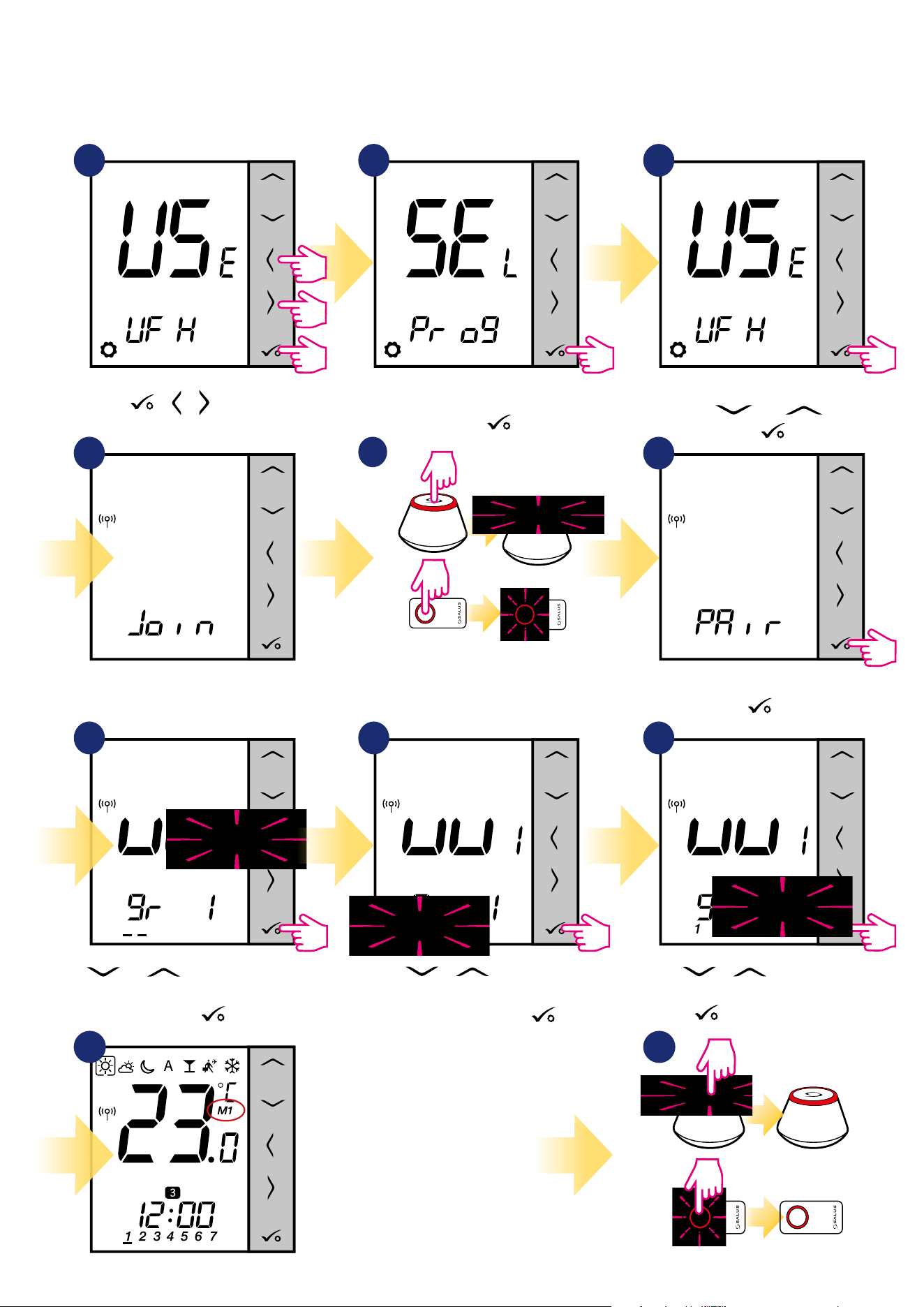
60
3
Set your thermostat for underoor
heating by „ ” or „ ” buttons.
Conrm by button.
In this chapter you will learn how to set VS10WRF/VS10BRF thermostat as a group controller (MASTER) or group thermostat (SLAVE). Please look at the
instructions below:
VS10WRF/VS10BRF AS A GROUP CONTROLLER (MASTER):
7.2.2 Grouping - installation of the thermostat as a group controller - MASTER - or as a group thermostat (SLAVE)
1 2
5 sec.
5 sec.
5 sec.
Hold buttons for 5
seconds to expand menu.
Set thermostat as a programmable
and conrm by
button.
+ +
4
Now thermostat is looking for the
signal from the coordinator...
5
Open the ZigBee network.
OR
5 sec.
5 sec.
6
7 98
Using and buttons select the KL08RF
number (press PAIR button on the KL08RF to see
its address number). Press button to conrm.
Use or buttons to set
thermostat as a group controller „MASTER”
(choose number 1).
Conrm by
button.
Thermostat has caught the signal from the
coordinator.
Press button to conrm.
Use or buttons to select
the KL08RF zone number and press
button to conrm.
1110
Close the ZigBee network.
Thermostat has been set as
a MASTER controller of the
group. You can see “M1” next
to temperature on the display
as a conrmation.
OR
3
3
5 sec.
5 sec.
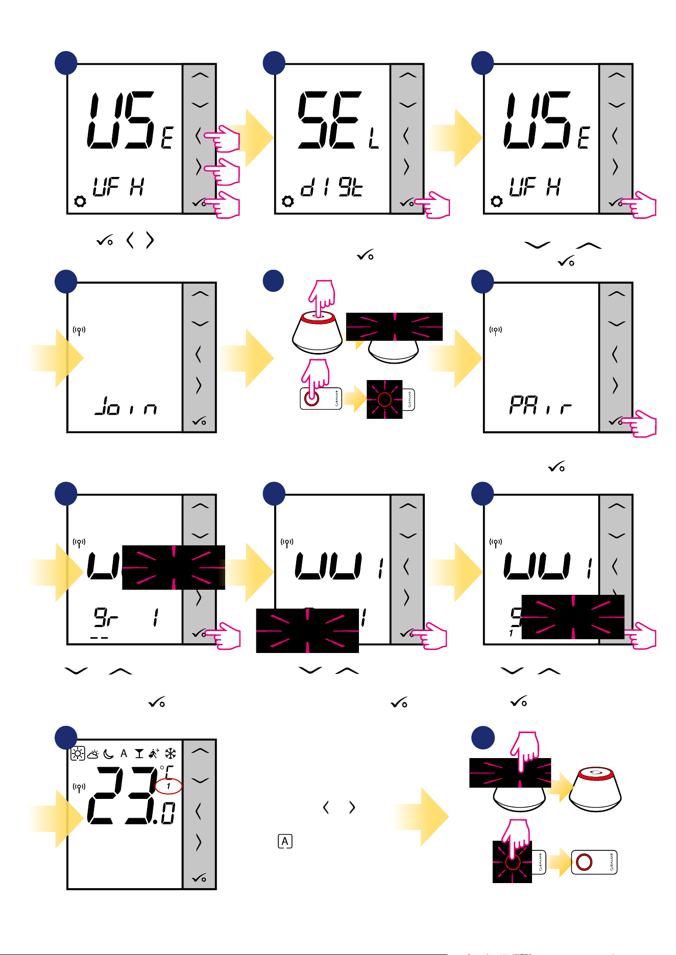
61
3
Set your thermostat for underoor
heating by „ ” or „ ” buttons.
Conrm by button.
Now you have to set dierent VS10WRF/VS10BRF as a slave thermostat:
1 2
5 sec.
5 sec.
5 sec.
Hold buttons for 5
seconds to expand menu.
Set thermostat as a non-programmable
and conrm by
button.
+ +
4
Now thermostat is looking for the
signal from the coordinator...
5
Open the ZigBee network.
OR
5 sec.
5 sec.
6
7 98
Using and buttons select the KL08RF
number (press PAIR button on the KL08RF to see
its address number). Press button to conrm.
Thermostat has caught the signal from the
coordinator.
Press button to conrm.
Use or buttons to select
the KL08RF zone number and press
button to conrm.
11
Close the ZigBee network.
Thermostat has been set as a
SLAVE thermostat. You can see “1”
next to temperature on
the display and lack of clock as
a conrmation. Use or
buttons and
choose - then SLAVE
thermostat will follow MASTER
goup controller.
OR
3
3
5 sec.
5 sec.
Use or buttons to set
thermostat as a group thermostat „SLAVE”
(choose number 2).
Conrm by
button.
10
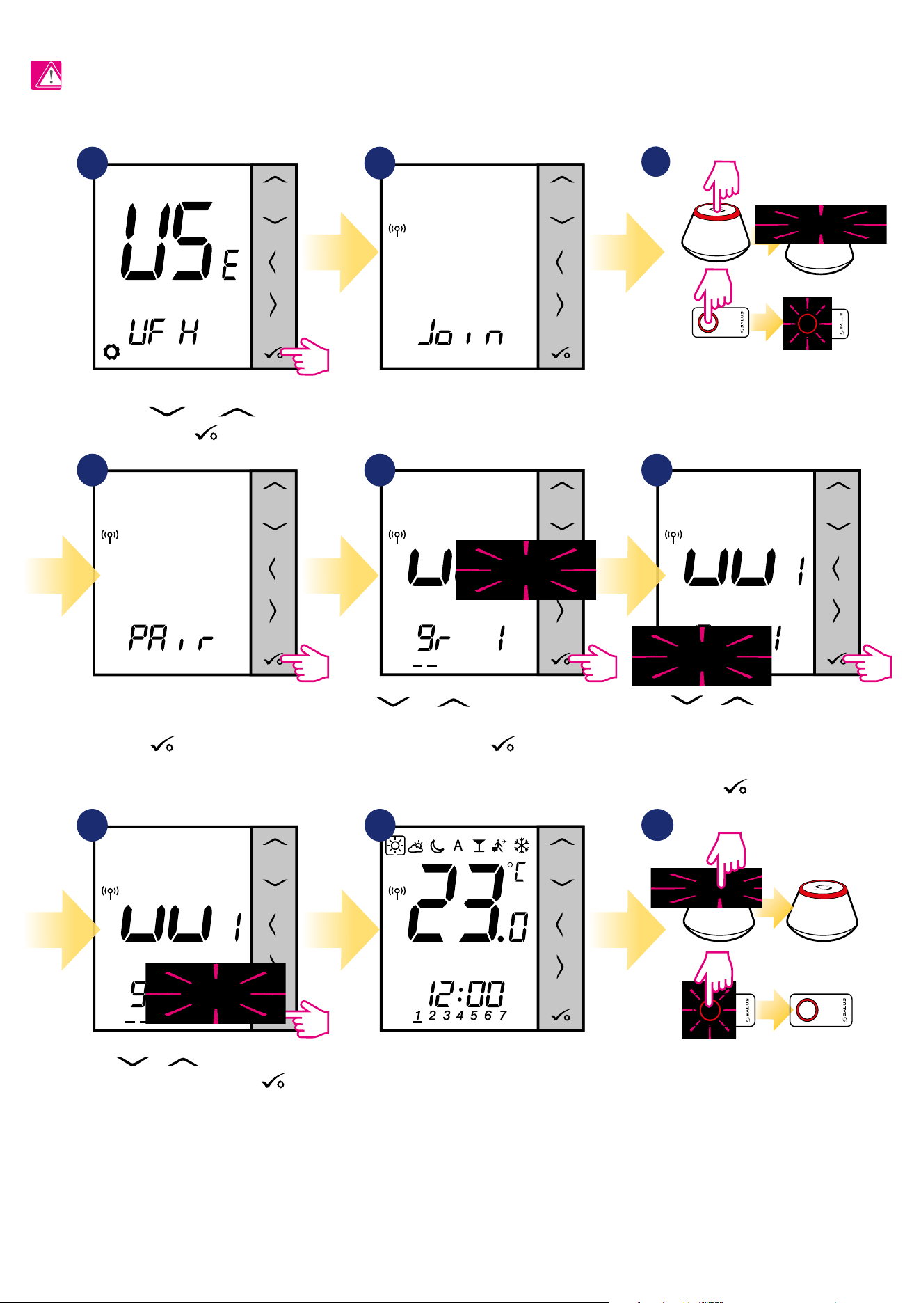
62
7.2.3 Installation as a programmable thermostat
1
4 5
7 8
6
2
Using and buttons select the KL08RF
number (press PAIR button on the KL08RF to see
its address number). Press button to conrm.
Use or buttons to group the
thermostat in the KL08RF as a one of two
areas with 4 zones (8 zones in control box
in total 2 areas, without KL04RF extension)
and press button to conrm.
Now thermostat is looking for the
signal from the coordinator...
Thermostat has caught the
signal from the coordinator.
Press button to conrm.
When thermostat is succesfully
paired, main screen will be
displayed.
PLEASE NOTE!
For easier installation, please make sure you have already added Underoor Heating Wiring Centre / Control Box KL08RF to your ZigBee network (please
refer to the wiring centre manual instruction).
Set your thermostat for underoor
heating by „ ” or „ ” buttons.
Conrm by button.
3
Open the ZigBee network.
OR
5 sec.
5 sec.
Use or buttons to select
the zone number and press
button to conrm.
9
Close the ZigBee network.
OR
3
3
5 sec.
5 sec.
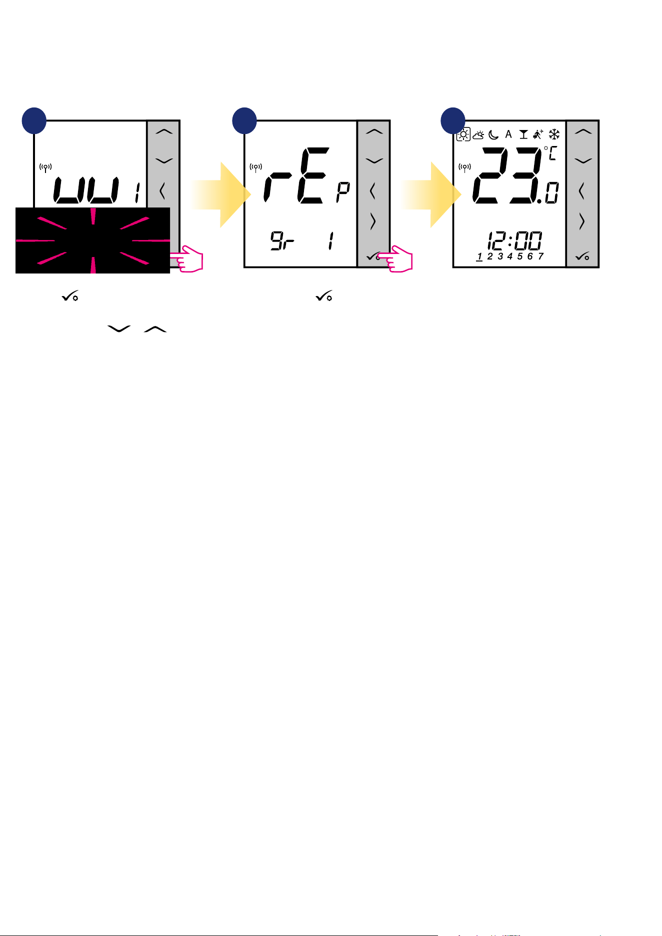
63
You can replace zone on the wiring centre, which is occupied by other thermostat (it will remove it from that zone). To do it follow steps below:
1 2 3
Press button to conrm zone
replacement. You can always change
the zone using or
buttons if you don’t want to replace
it.
Conrm by button.
When thermostat is succesfully
paired, main screen will be
displayed.
3
7.2.4 Replace the zone assigned to another thermostat
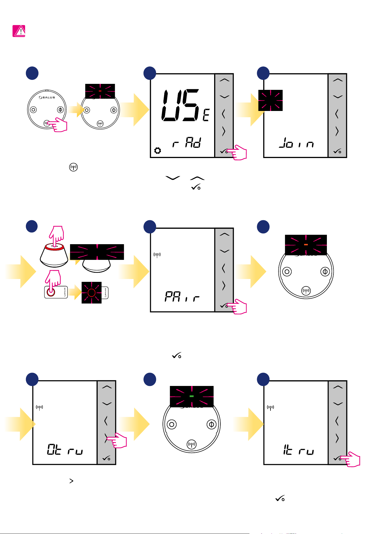
64
2
Set your thermostat for radiators
by or buttons.
Conrm by button.
7.3 Pairing with wireless TRV radiator head
On the LCD you will see the number of
paired TRV’s. Once all TRV’s are paired -
press button to nish the pairing
process.
PLEASE NOTE!
For easier installation, please make sure you have already added wireless TRV radiator heads to your ZigBee network (please refer to the wireless TRV
radiator head manual instruction).
5
9
3
Now thermostat is looking for the
signal from the coordinator...
4
Open the ZigBee network.
OR
5 sec.
5 sec.
The thermostat has been added to
the ZigBee network and paired with
the gateway/coordinator.
Press button to conrm.
Press button.
Thermostat is searching for TRVs
radiator heads...
7
1
8
6
Hold the button for 10 seconds,
The LED on the head should start
to blink red. You can pair up to 6 TRV’s with 1
thermostat. All TRV’s have to be within the
same room with thermostat.
10 sec
Device is paired with coordinator,
diode on the TRV will start to blink
orange.
Diode on the TRV will light up once
green and stop blinking.
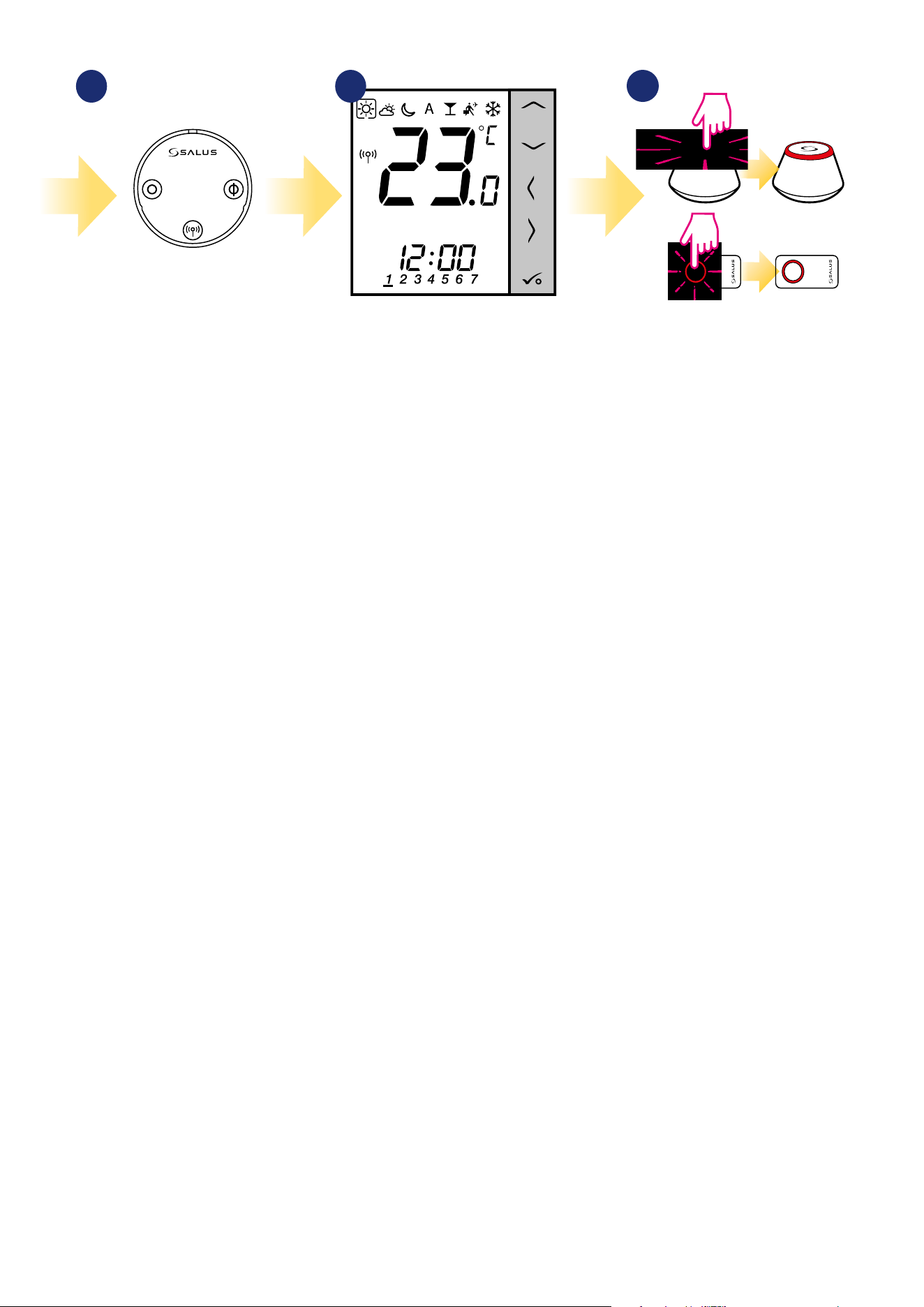
65
11
12
Close the ZigBee network.
OR
3
3
5 sec.
5 sec.
When thermostat is succesfully
paired main screen will be
displayed.
10
TRV has been added.
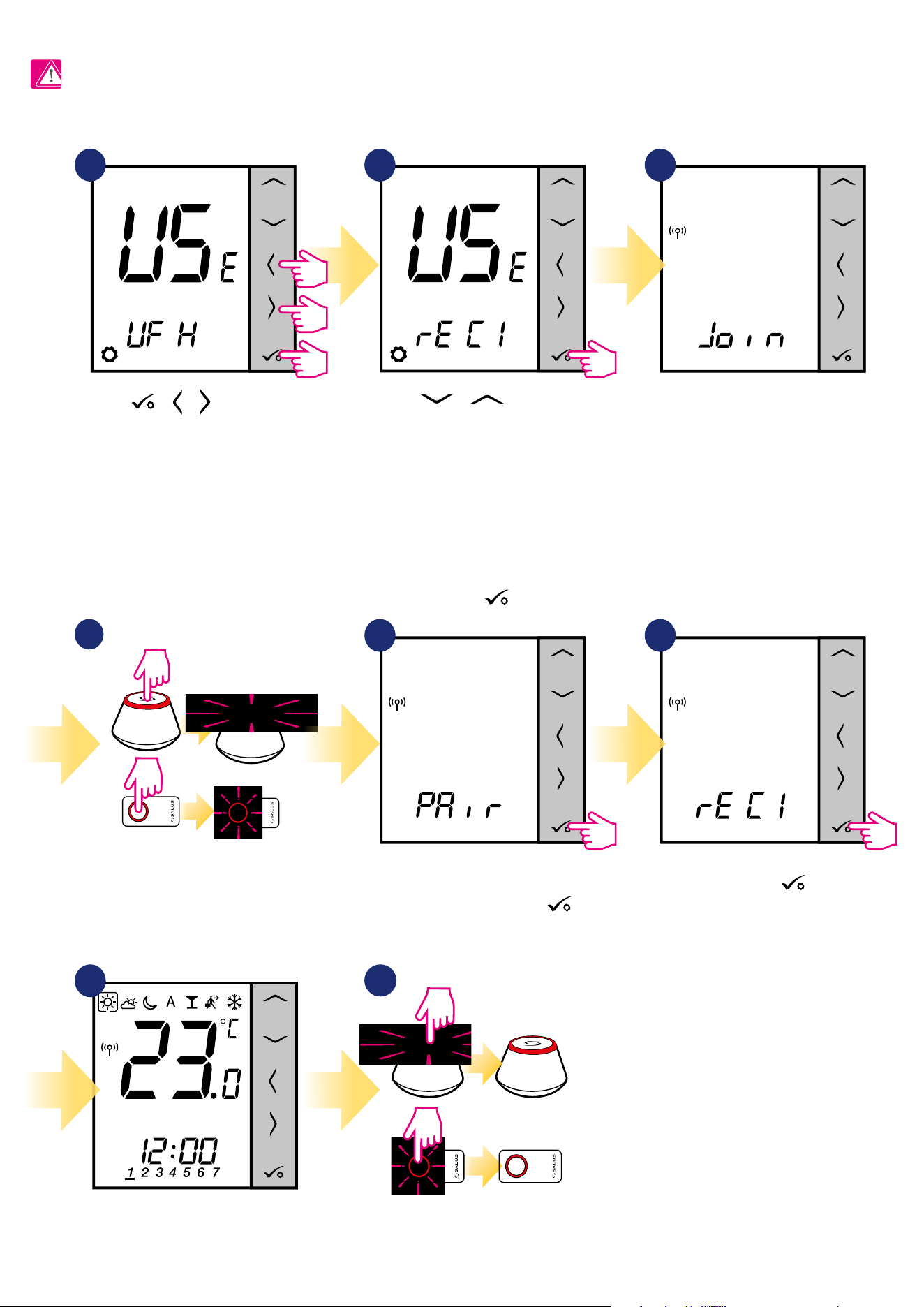
66
5
Thermostat has caught the signal
from the coordinator.
Press
button to conrm.
6
Conrm choice by
button.
7.4 Pairing with RX10RF receiver
Use or buttons to:
- choose pairing with the RX10RF receiver in
the „RX1” conguration, if the receiver is set as
RX1 (receiver responds to the heating signal
from any thermostat),
- choose pairing with the RX10RF receiver in
the „RX2” conguration, if the receiver is set as
RX2 (receiver responds to the heating signal
only from one thermostat).
Conrm by
button
PLEASE NOTE!
For easier installation, please make sure you have already added RX10RF receiver to your ZigBee network (please refer to the RX10RF receiver manual
instruction).
2 3
Now thermostat is looking for the
signal from the coordinator...
4
Open the ZigBee network.
OR
5 sec.
5 sec.
8
Close the ZigBee network.
OR
3
3
5 sec.
5 sec.
7
When thermostat is succesfully
paired main screen will be
displayed.
1
5 sec.
5 sec.
5 sec.
Hold buttons for 5
seconds to expand menu.
+ +
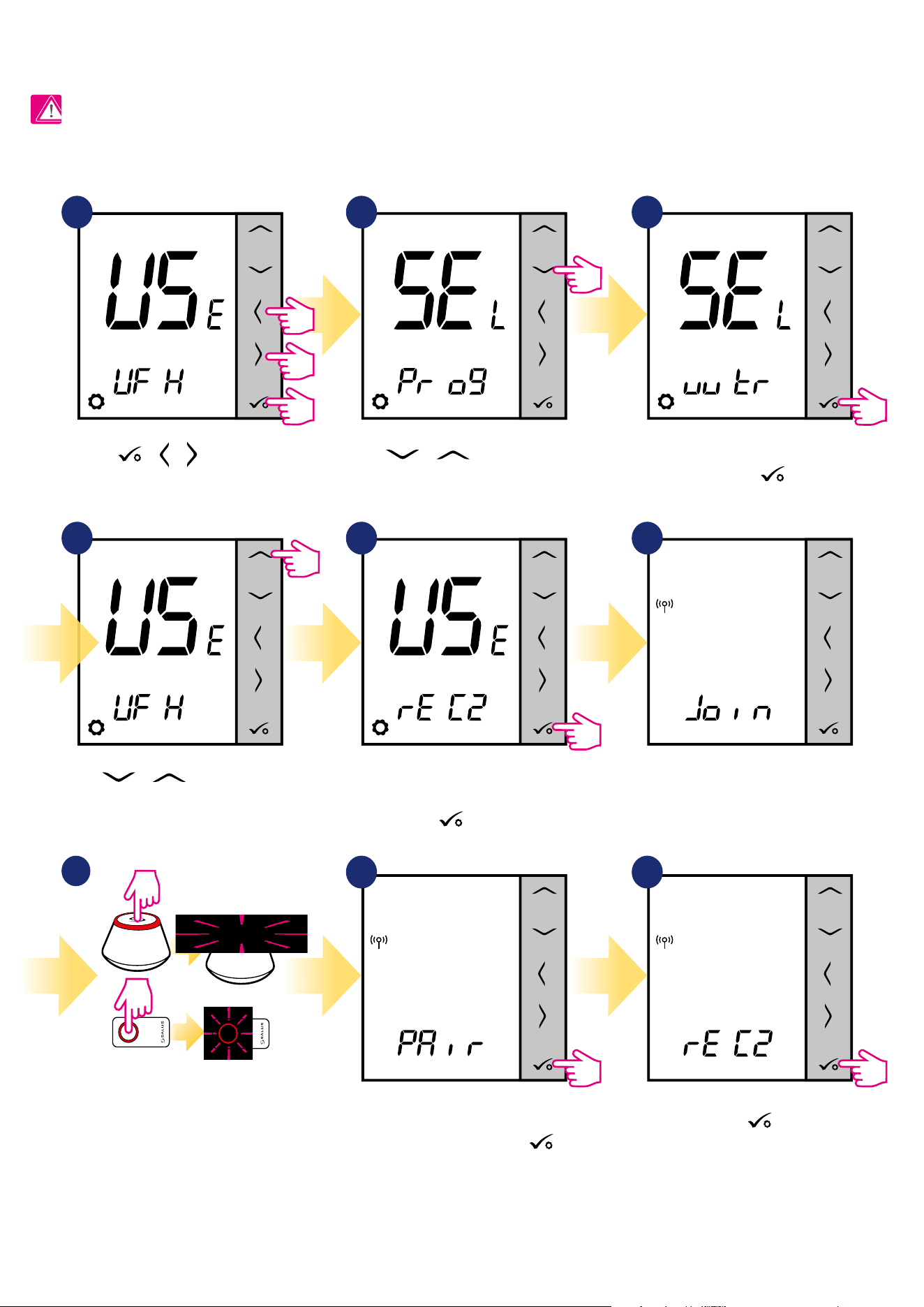
67
7.5 Conguration as a Hot Water timer
7.5.1 Pairing with Room Extension Receiver (RX2)
PLEASE NOTE!
For easier installation, please make sure you have already added other devices to your ZigBee network, such as Underoor Heating Control Box (KL08RF)
or RX10RF.
1
4
2
5 sec.
5 sec.
5 sec.
3
5 6
7
Open the ZigBee network.
OR
5 sec.
5 sec.
8 9
Thermostat has caught the signal
from the coordinator.
Press
button to conrm.
Conrm by button.
Hold buttons for 5
seconds to expand menu.
Use or buttons to move
between settings.
Use or buttons to move
between settings.
Pair thermostat with RX10RF
receiver as an RX2 option. Conrm
by
button.
Now thermostat is looking for the
signal from the coordinator...
Set thermostat as a hot water timer
and conrm by
button.
+ +
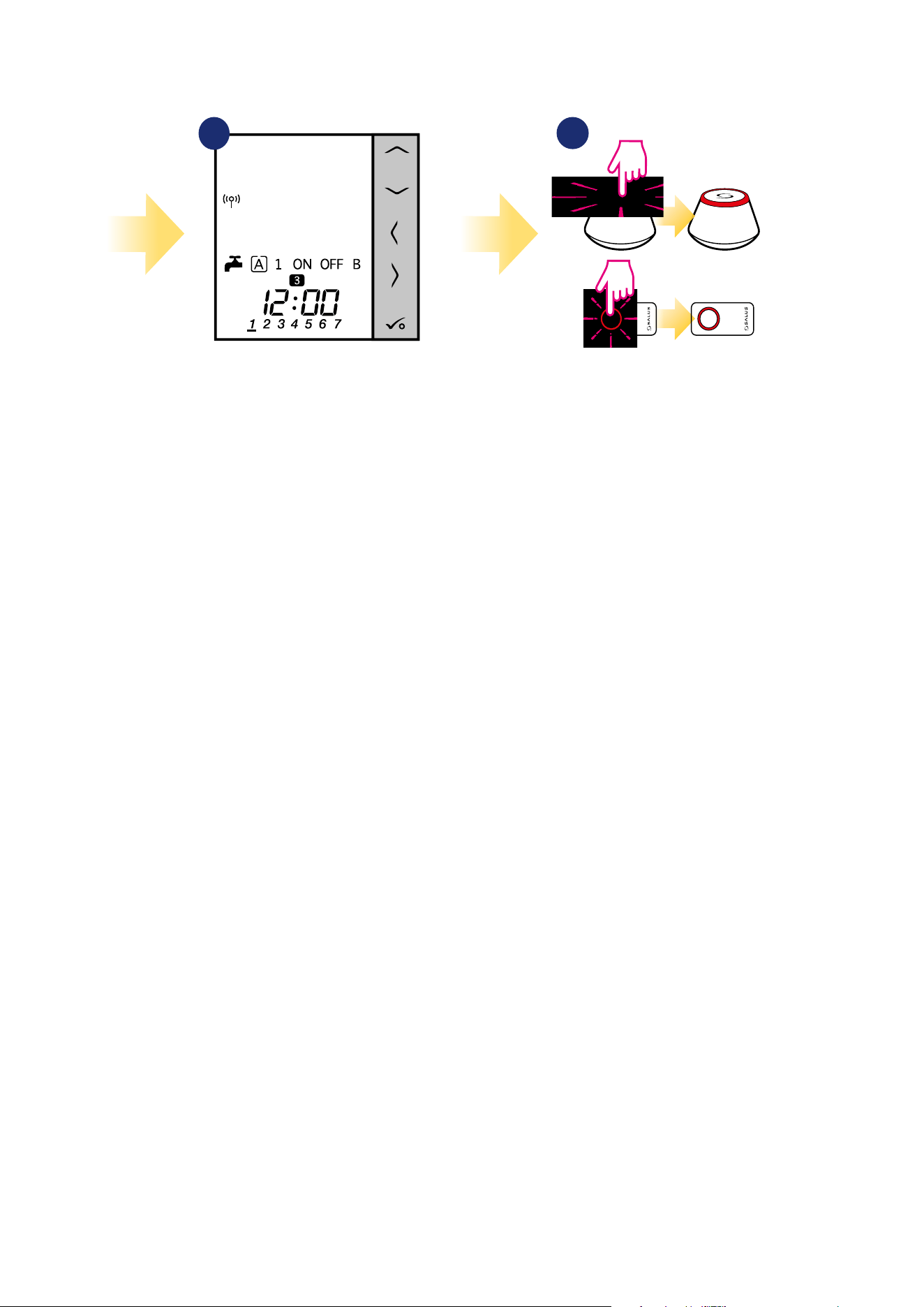
68
11
Close the ZigBee network.
OR
3
3
5 sec.
5 sec.
10
When thermostat is succesfully
paired main screen will be
displayed.
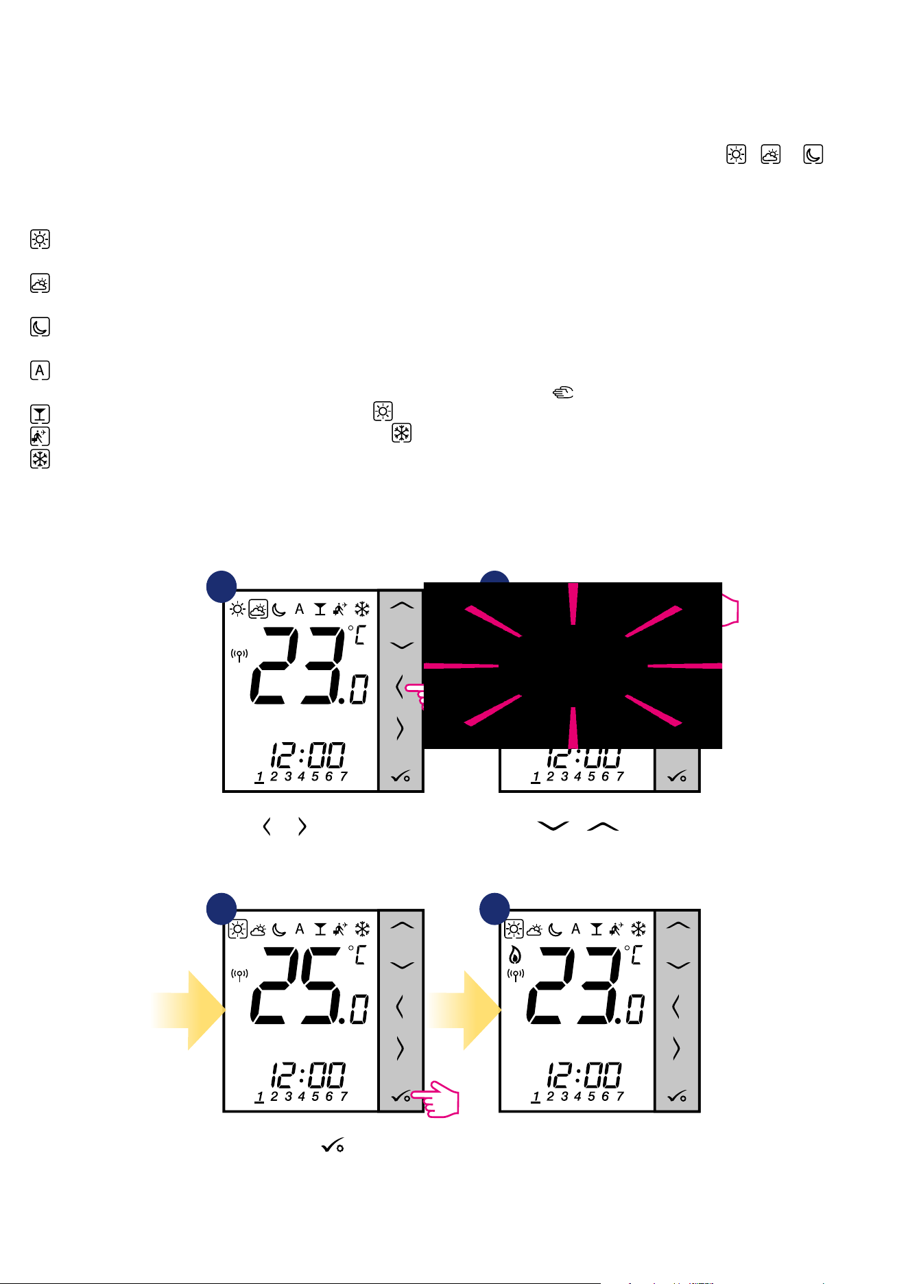
69
8. OPERATING in OFFLINE MODE
8.1 Work as a programmable thermostat
8.1.1 Work modes
Use or buttons to switch
between work modes.
1 2
43
Use or buttons set
temperature setpoint.
Conrm by button.
Thermostat will go back to the main
screen after saving the settings.
VS10WRF/VS10BRF oers few work modes. Frame on a given icon indicates which mode is currently active. In manual mode , or only one
temperature level is maintained. Thermostat follows programmed schedule when AUTO mode is active („A” icon). Detailed description of work modes is
located below:
Example - comfort temperature mode setpoint editing:
- Comfort temperature mode - pre-dened setpoint temperature. Usually set when we are indoors. The highest maintained temperature in
heating mode or the lowest if thermostat works in the cooling system. Acting alone works as a manual mode.
- Standard temperature mode - pre-dened setpoint temperature. Usually set during the day when we are around the house. Acting alone works
as a manual mode.
- Economic temperature mode - pre-dened setpoint temperature. Usually set at night or when we are out of the house. Acting alone works as a
manual mode.
- Automatic mode temperature (schedule) - follows programmed schedule. Schedule can be temporarily override with new setpoint
temperature (temporary override mode will be active to the next change forced by schedule, hand icon will be displayed).
- Party mode - this mode sets the comfort temperature for a user-dened time (maximum 9 hours 50 minutes).
- Holiday mode - this mode sets the frost protection mode for a user-dened time (maximum 99 days).
- Frost protection mode - usually used during extended periods of absence or during the holidays (only available in heating mode).
3
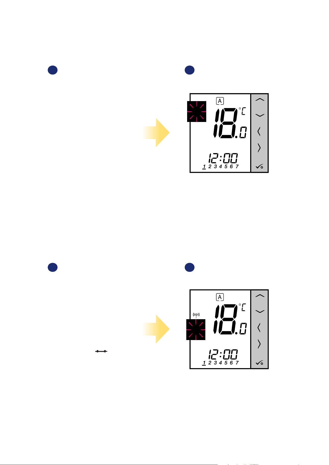
70
8.1.2 Heat/cool mode change (KL08RF connection)
VS10WRF/VS10BRF thermostat is designed to work in heating and cooling systems. By default thermostat is set to heating mode. To change from heating
to cooling mode it’s necessary to insert jumper into „CO” terminal (KL08RF wiring centre). Look at the instructions below:
When thermostat is calling for cooling,
then snowake icon is displayed.
When thermostat is calling for heating,
then ame icon is displayed.
1
„CO” terminal of the KL08RF wiring centre - if contacts are closed,
then all thermostats paired with KL08RF are in cooling mode.
2
1 2
„CO” terminal of the KL08RF wiring centre - if contacts are opened,
then all thermostats paired with KL08RF are in heating mode.
COOLING MODE:
HEATING MODE:
3
3
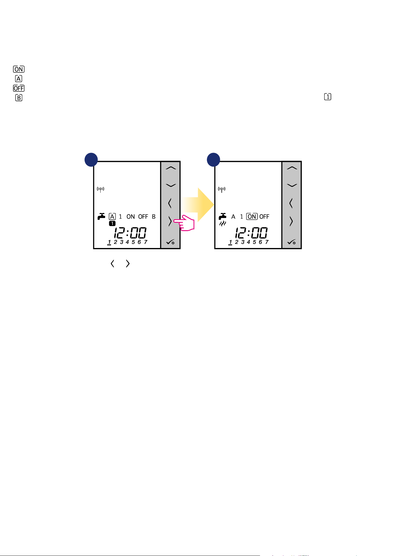
71
8.2 Work as a hot water timer with RX10RF receiver
8.2.1 Work modes
VS10WRF/VS10BRF thermostat as a Hot Water timer has 4 modes available:
- Turned ON - thermostat is manually turned on and work as long as you change this mode to another or switch it o,
- AUTO mode - thermostat is following schedule which you programmed - look at chapter 8.4.1 Schedule mode, page 65,
- Turned OFF - thermostat is manually turned o as long as you select other mode,
- Temporarily ON mode - you can fast set the water heating time in this mode in limited hour period (from 1 to 4 hours - ).
1 2
Use or buttons to switch
between work modes.
Thermostat has been set
to the selected mode.
Example - setting the „Turned ON” mode:
3
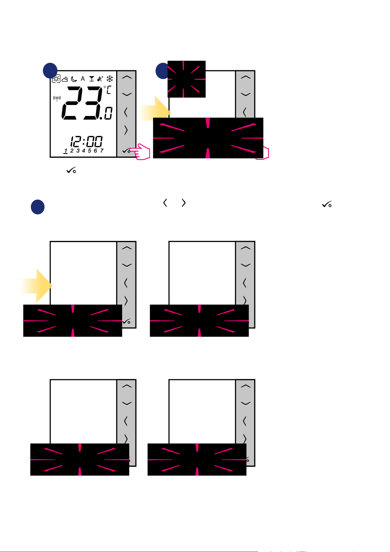
72
8.3 User settings (basic settings)
8.3.1 Schedule mode - programming schedule
To program schedule in oine mode please follow steps below:
There are 4 possible schedule variants. Use and buttons to select schedule variant and conrm by button:
Separate schedule for WORKING DAYS. Separate schedule for WEEKENDS.
One schedule for
WHOLE WEEK
Seven separate schedules for
SINGLE DAYS
1
2
3
Enter into the schedule settings.
Hold button for 3 seconds to
enter the menu.
3 sec.
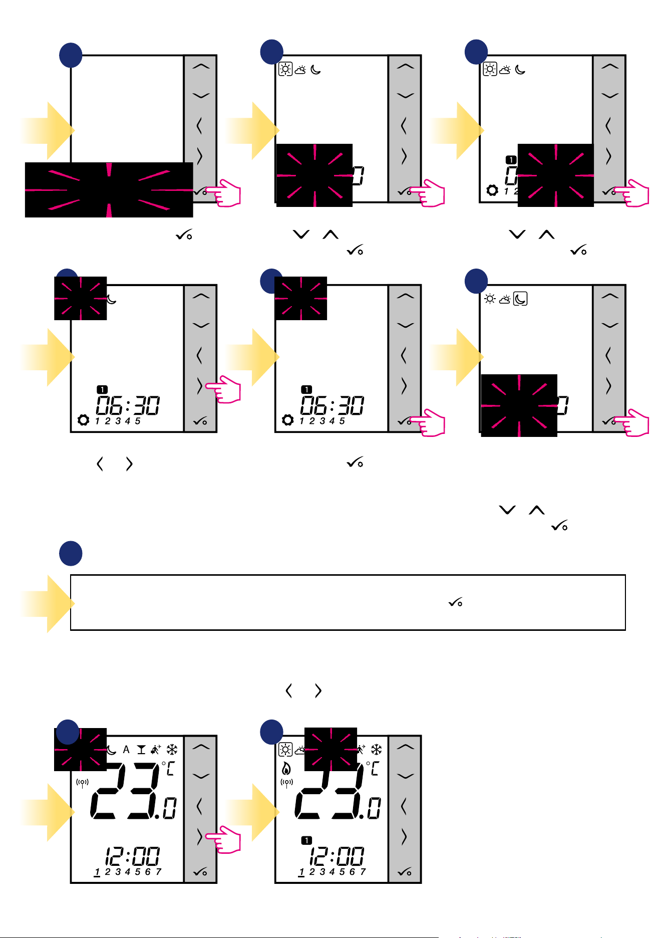
73
Select schedule variant by
button.
Use or buttons to set hour.
Conrm by button.
Use or buttons to set
minutes. Conrm by button.
Repeat steps 5 and 9 for the next time periods in the schedule to set whole program for selected variant. No time --:-- on the display
means given program is skipped. There are 6 programs/time periods in the schedule. Hold button for 3 seconds to save and exit
schedule editing.
To run the schedule (activate thermostat’s automatic mode), use and buttons to move the frame to the „A” icon.
Schedule programming example for the WORKING DAYS variant:
10
4
5 6
8 97
Use and buttons to choose
comfort, standard or economic
setpoint temperature.
Schedule editing will jump to the
next program’s time setting.
Set time for selected mode using
or buttons again.
Conrm by button.
Conrm by button.
1 2
3
3
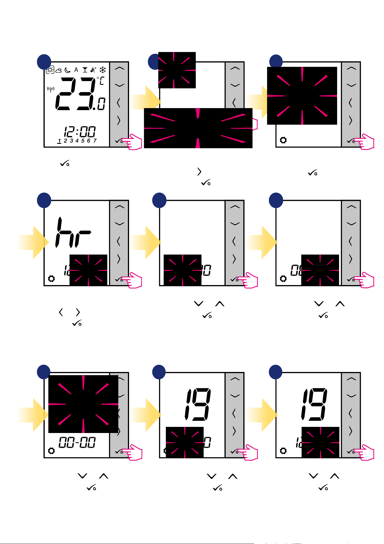
74
8.3.2 Time/Date
Time/date change or edit can be done only in Oine mode. In Online Mode thermostat will synchronise current time and date based on information
taken from the Internet. To set time/date follow steps below:
1
Set hour using and buttons.
Conrm by
button.
Set month using and
buttons. Conrm by
button.
Set year using and buttons.
Conrm by
button.
Set minutes using and buttons.
Conrm by
button.
Set day using and buttons.
Conrm by
button.
3
DATE settings will automatically appear after clock setup:
Hold button for 3 seconds to
enter the menu.
Go to the time and date settings
using button.
Conrm by button.
Choose time and date settings option
by button.
First, select time format (12/24h)
using and buttons. Conrm by
button.
7
8 9
3 sec.
4 5 6
2
3
3
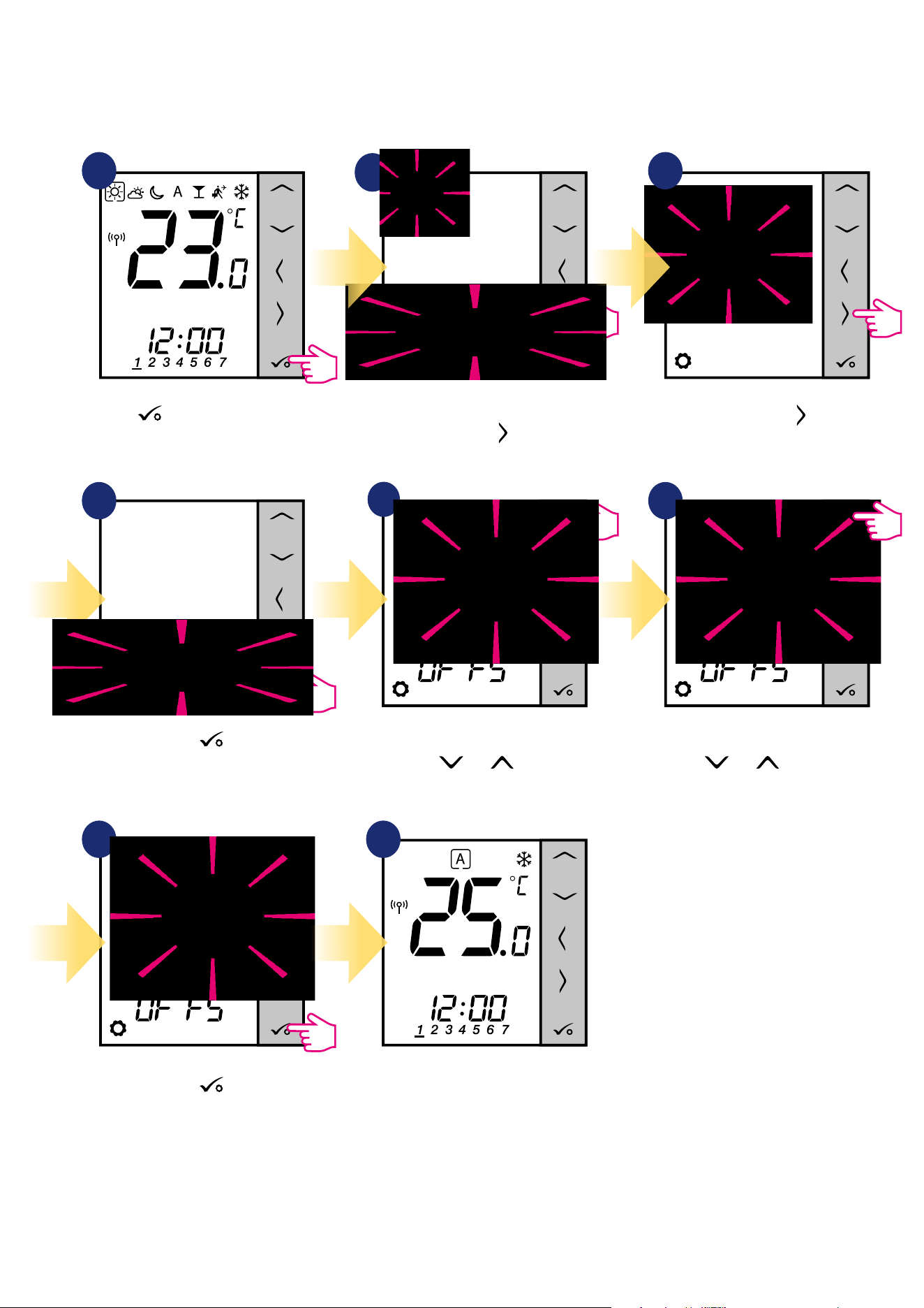
75
8.3.3 Thermostat calibration
Thermostat calibration is a function which allows user to recalibrate internal thermostat’s temperature sensor by a given number of degrees (in the range
from -3,0 °C to 3,0 °C in 0,5 °C steps). To calibrate thermostat’s temperature sensor please follow steps below:
1
4
7
6
Set temperature calibration value
using and buttons.
To increase/decrease value use
and buttons.
Go to the thermostat calibration
settings using button.
Move forward using button.
5
2
3
8
Hold button for 3 seconds to
enter the menu.
3 sec.
Conrm by button.
Conrm by button.
Thermostat will go back to the main
screen after saving the settings.
3
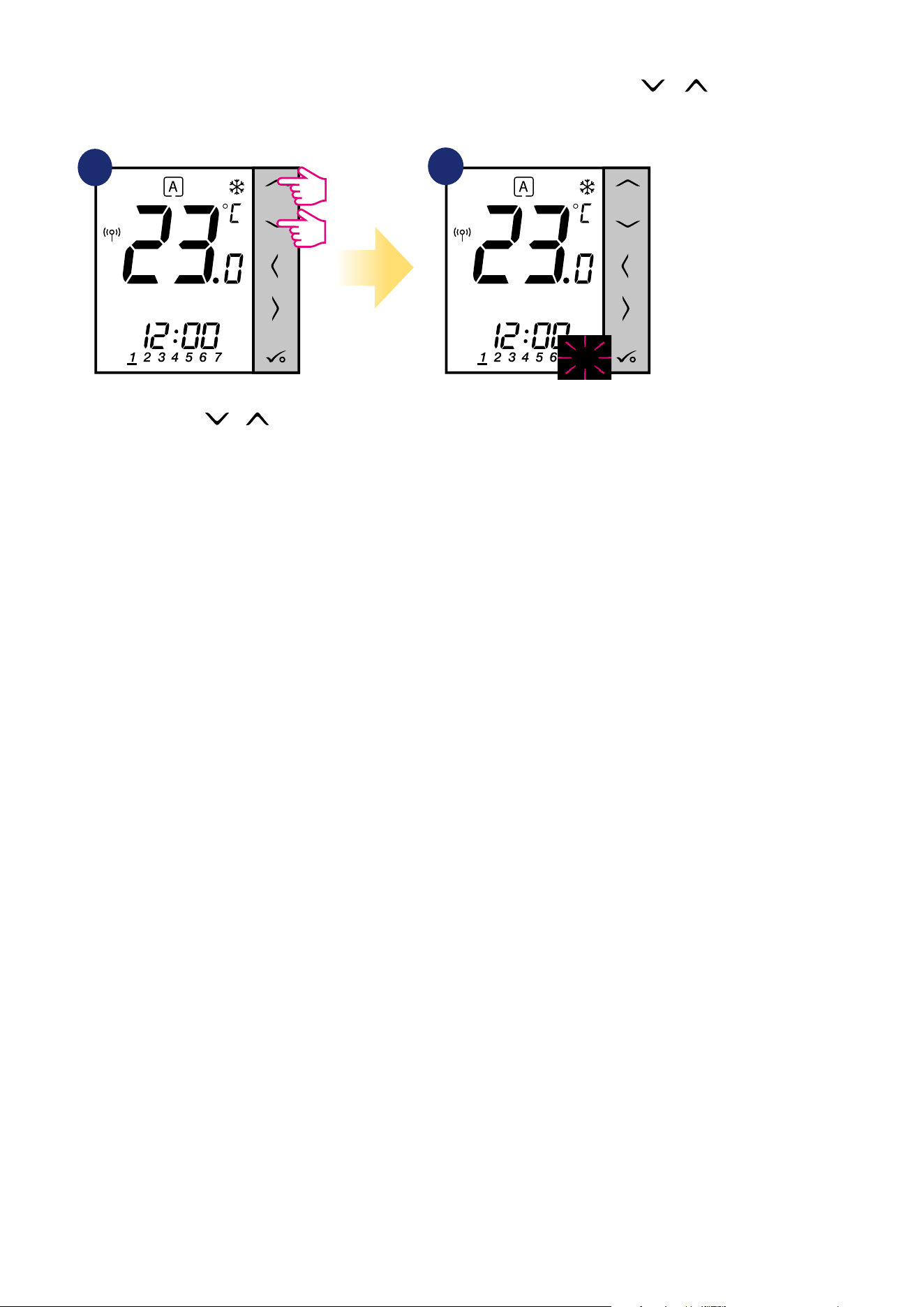
76
3 sec.
3 sec.
8.3.4 Key lock function
To LOCK/UNLOCK VS10WRF/VS10BRF thermostat keys in OFFLINE MODE you have to press and hold + buttons for 3 SECONDS. When
thermostat is locked, you will see padlock icon on the display. When thermostat is unlocked padlock icon is not visible.
1
2
3
Press and hold
+
buttons for 3 seconds.
Thermostat is locked and key icon is
displaying.
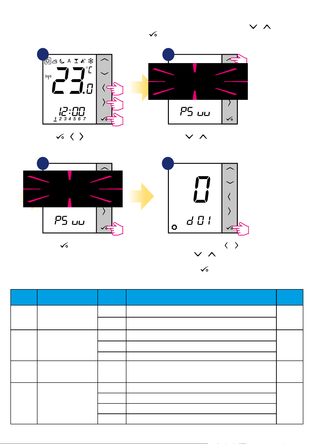
77
9. Installer parameters
To enter installer parameters please follow steps below. Please refer to parameters table description before any changes. Use or buttons to move
up or down between all parameters. Every change/selection conrm by button:
1
3
Use or to choose
code „49”.
Press button to conrm.
Select installer parameter by or
buttons. Use or buttons to
change parameter value. Conrm
choice by button.
5 sec. 5 sec. 5 sec.
4
2
Hold buttons for 5
seconds to enter the installer mode.
+ +
dXX Function
Parameter
Values
Description
Default
Values
d00 Temperature unit
0 Celsius [°C]
0
1 Fahrenheit [°F]
d01
The method of controlling the
temperature of the heating
system
0 by TPI algorithm
0
1 SPAN ±0.5°C
2 SPAN ±1.0°C
d02
Correction of the displayed
temperature
from -3.0°C
to +3.0°C
If the thermostat indicates an incorrect temperature,
it can be corrected by ± 3.0°C
0°C
d03
Floor temperature sensor use
(S1,S2)
0 No sensor
0
1 Temperature sensor connected
2 Dew point sensor connected (only in UFH)
3 Occupancy sensor connected
3
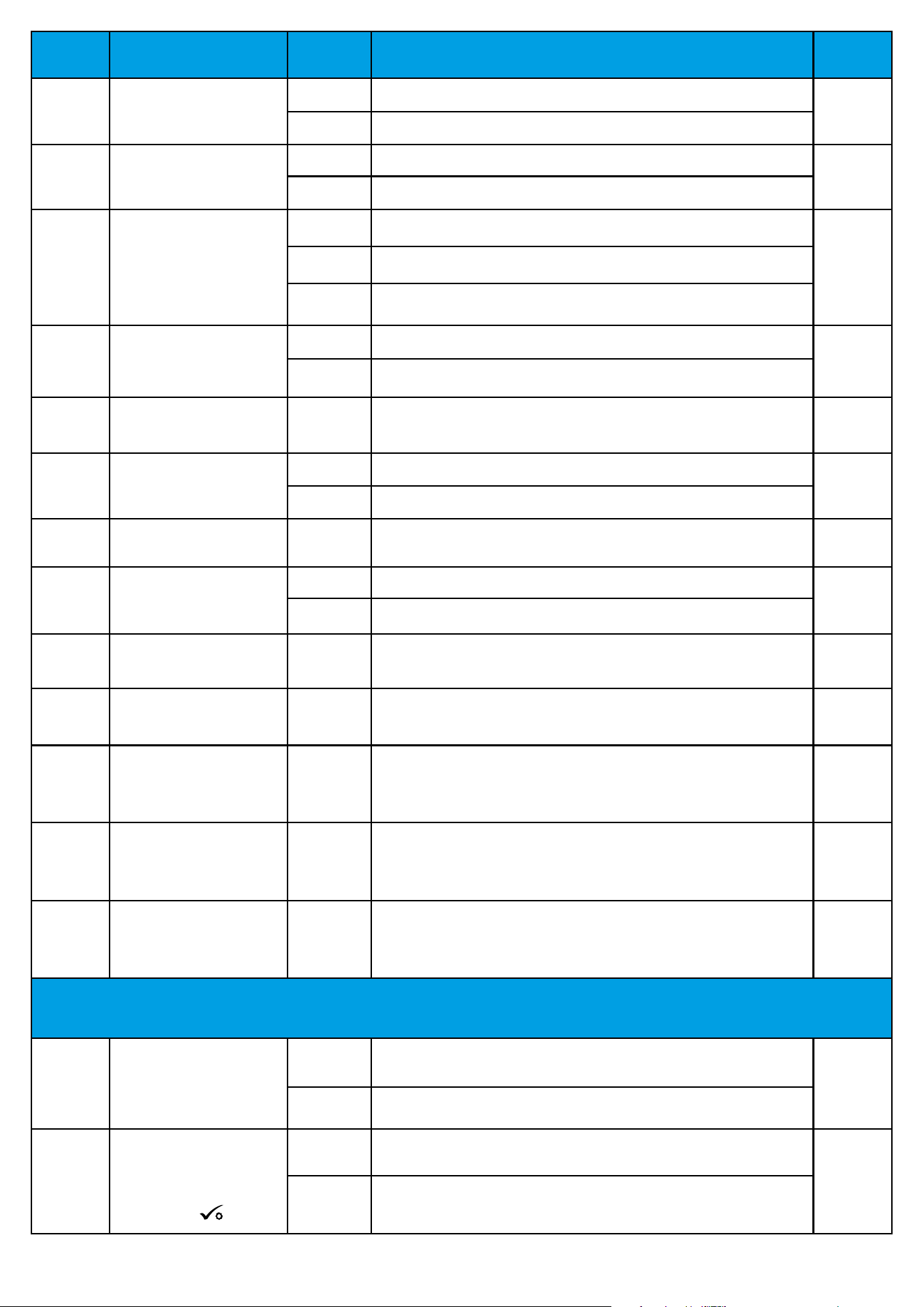
78
dXX Function
Parameter
Values
Description
Default
Values
d04
Internal relay
(active when d03=1)
0 The controller measures the temperature only at the external sensor
0
1 The sensor is used as a protection against overheating of the oor
d05 (only
in UFH)
Control of the cooling mode
1
SPAN ±0.5°C
2
2
SPAN ±1.0°C
d06 (only
with TRV)
TRV control algorithm
0
Standard ON/OFF algorithm
1
1
Automatic selection
2
Advanced self-learning algorithm
d07 Valve protection
0 Disable
1
1 Enable
d08 Frost protection temperature 5-17°C Frost protection temperature (and for holiday mode) 5°C
d09 Time format
0 12 hours
1
1 24 hours
d10
Time zone (reserved for
internet wireless)
from -13 to
+13 hours
It gives you the possibility to t the thermostat time zone to yours
(every 1 hour step).
0
d11 Summer time change
0 Disabled
1
1 Enabled
d12 Heating temperature limit 5-35°C Maximum heating/cooling temperature that can be set by the user 35°C
d13 Cooling temperature limit 5-40°C Minimum heating/cooling temperature that can be set by the user 5°C
d14
Max oor temperature
(active in heating mode when
d04=1)
6-45°C
To protect the oor against overheating, the heating will be switched o when
the maximum temperature of the oor sensor is reached.
27°C
d15
Min oor temperature
(active in heating mode when
d04=1)
6-45°C
To protect the oor, heating will be activated when the minimum oor sensor
temperature has been reached.
10°C
d16
Lower oor temperature limit
for cooling (Function active
when d04 = 1).
6-45°C
To protect the oor, cooling will be switched o when the set minimum
temperature is reached.
6°C
FEATURES AVAILABLE ONLY FROM THE APPLICATION LEVEL:
d17
Allow buttons to be unlocked
from the thermostat
0 OFF
1
1 ON
d18
Deactivate the need to
conrm the change of the
temperature setpoint by
pressing the button.
0 OFF
0
1 ON
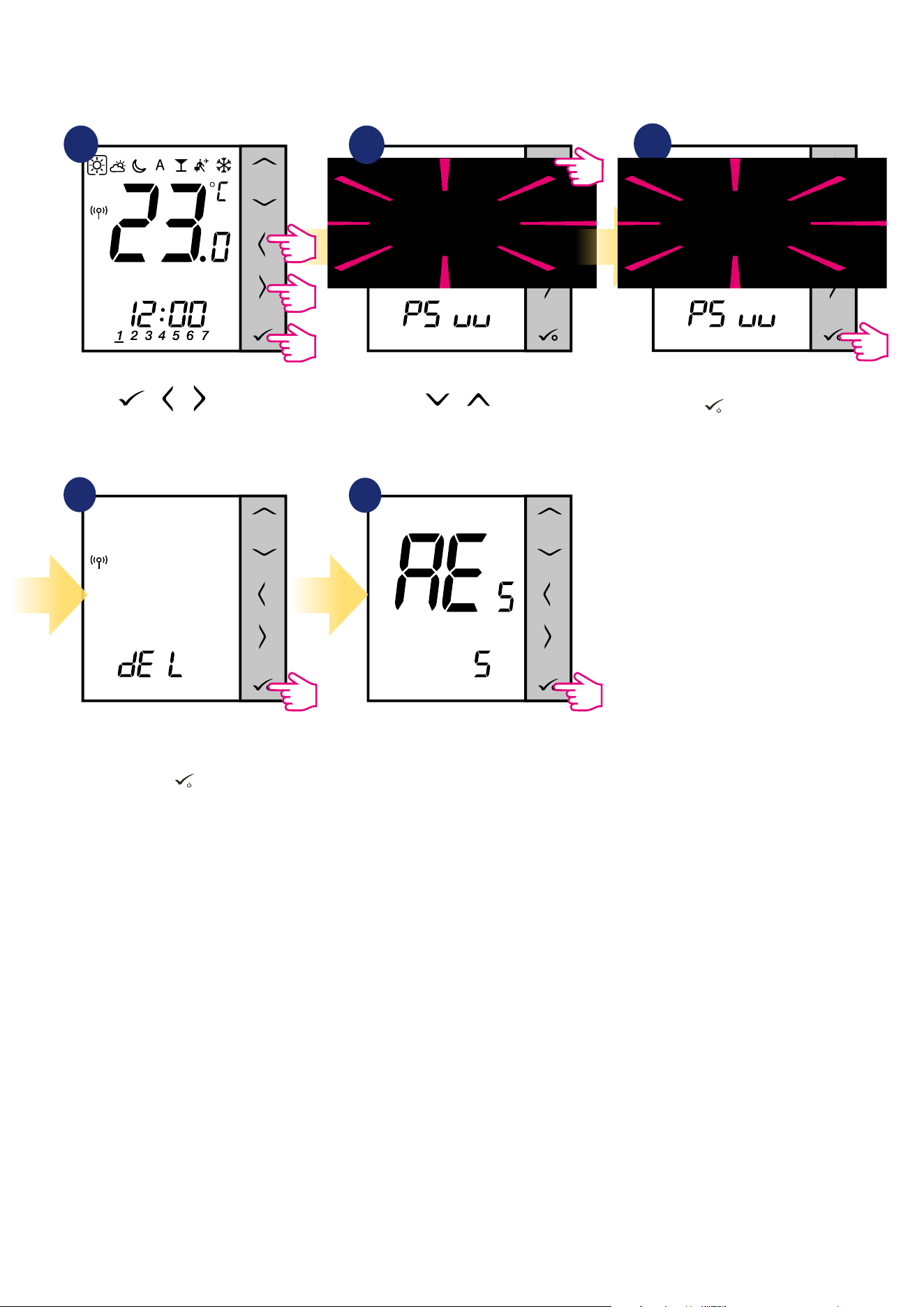
79
10. Factory Reset
To RESET VS10WRF/VS10BRF thermostat to it’s factory default settings please follow steps below:
1
2
3
4
5
Wait few moments to nish factory
reset procedure.
Use or buttons
to choose code „47”.
Hold buttons for 5
seconds to enter the installer mode.
Press
button to conrm.
Select „del” and conrm choice by
pressing
button
.
5 sec.
5 sec.
5 sec.
+ +
3
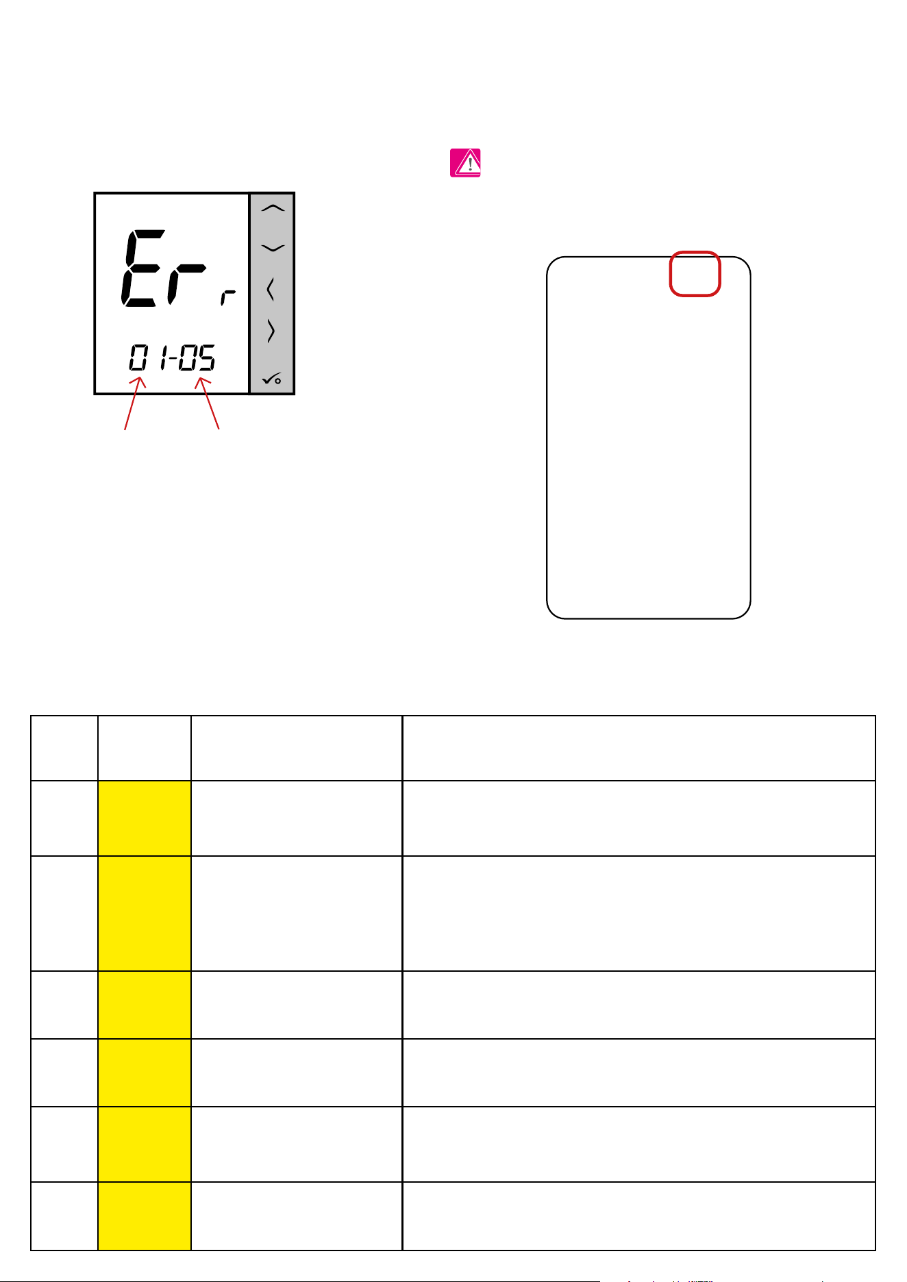
80
11. Error codes (error codes description with possible solutions)
Error codes description with possible solutions:
ERROR
CODE
DISPLAY
DESCRIPTION
ERROR DESCRIPTION TROUBLESHOOTING
1.
Err
XX-01
TRV paired with thermostat - TRV
hardware error.
• Reinstall the TRV head or replace it. If necessary, contact with the
SALUS Technical Department.
2.
Err
XX-02
Floor is overheated (heating mode).
/ Floor is overcooled (in cooling
mode).
• Set the heating medium temperature or change D14 parameter.
• Set the cooling medium temperature or change D16 parameter.
3.
Err
XX-03
Floor sensor is broken.
• If oor sensor is connected to S1/S2 input, check the wiring.
• If oor sensor is not connected, check the D03/D04 parameters settings.
4.
Err
XX-04
Floor sensor is shorted.
• Check oor sensor wire insulation for any damages. Sensor resistance for
25°C=10kΩ.
5.
Err
XX-05
Thermostat lost contact with the
CO10RF network coordinator or the
UGE600 internet gateway.
• Check the coordinator/gateway power supply connection.
• Force identication process from the coordinator/gateway or thermostat.
6.
Err
XX-06
Thermostat lost connection with the
wiring centre.
Is the wiring centre turned ON and Status Network LED diode solid?
• If yes, send the heating signal from thermostat to the wiring centre
Thermostat constantly monitors the network status, wireless connection status and the operation of connected sensors or paired devices. If it detects any
failure then following error codes can be displayed alternately with the current room temperature value.
Number of errors Error code
In Online mode error is also shown in the Smart Home application (with
detailed description). Exclamation mark informs user about existing errors.
PLEASE NOTE!

81
(change setpoint temperature).
• If LED diode of the Network Status is ashing, pair the wiring centre with
the system in accordance to the manual instruction and pair thermostat
with wiring centre.
7.
Err
XX-07
Thermostat lost contact with the TRV
head.
• Check TRV head batteries.
• Send the heating signal from thermostat and check if the TRV
head is working.
• If the LED diode on the TRV head is ashing, repeat the pairing
procedure with thermostat according to the manual instructions.
8.
Err
XX-08
Thermostat has lost connection with
the RX10RF receiver (RX1 mode).
• Is the RX10RF receiver plugged to the power supply and the top
LED diode is red? The Auto/Manual switch has to be set to AUTO
position.
• Force identication process from the coordinator/gateway side
and check if the devices are within the network.
• Send the heating signal from thermostat
• If the top LED diode is ashing, perform the pairing procedure
according to the RX10RF manual instruction.
9.
Err
XX-09
Thermostat has lost connection with
the RX10RF receiver (RX2 mode).
• Is the RX10RF receiver plugged to the power supply and the top
LED diode is red? The Auto/Manual switch has to be set to AUTO
position.
• Force identication process from the coordinator/gateway side
and check if the devices are within the network.
• Send the heating signal from thermostat
• If the top LED diode is ashing, perform the pairing procedure
according to the RX10RF manual instruction.
10.
Err
XX-10
KL10RF wiring centre has lost
connection with the DHW time
programmer. Error is displayed on
all thermostats and on the DHW
programmer.
Is the wiring centre turned ON and Status Network LED diode solid?
• If yes, send the heating signal from DHW programmer to the
wiring centre.
• If LED diode of the Network Status is ashing, pair the wiring
centre with the system in accordance to the manual instruction and
pair DHW timer with wiring centre.
11-18.
Err
XX-11
XX-18
Wiring centre has lost connection
with thermostat of the given zone:
e.g. 11 = with zone 1; 12 = with the
zone 2 etc. Error is displayed on all
thermostats.
• Check the thermostat power supply.
• Send the heating signal from thermostat.
• If necessary, reinstall the thermostat.
19.
Err
XX-19
Wiring centre has lost connection
with the CO10RF coordinator/UGE600
internet gateway.
Error is displayed on all thermostats.
• Is the wiring centre turned ON and Status Network LED diode
solid?
• Force identication process from the coordinator/gateway side
and check if wiring centre is within the network.
• If LED diode of the Network Status is ashing, pair the wiring
centre with the system in accordance to the manual instruction and
pair all thermostats with wiring centre.
ERROR
CODE
DISPLAY
DESCRIPTION
ERROR DESCRIPTION TROUBLESHOOTING
82
22.
Err
XX-22
Low battery level in the TRV head.
• Replace TRV head batteries.
23.
Err
XX-23
TRV head’s pairing error or head is
incompatible with the system.
• Remove TRV head from the system and repeat pairing procedure with
thermostat.
24.
Err
XX-24
Thermostat was rejected by the
wiring centre.
• Perform the thermostat’s pairing procedure again.
25.
Err
XX-25
Thermostat has lost connection with
the nearest 230V powered device.
• Check the power supply of the nearest 230V device. If there is problem
with RF signal range, install the ZigBee Network Repeater and pair
thermostat with the receiver again (wiring centre, TRV head etc.)
26-29.
Err
XX-26
XX-29
Wiring centre has lost connection
with thermostat of the given zone:
e.g. 26 = with zone 9; 27 = with
zone 10; 28 = with zone 11, 29 =
with zone 12. Error is displayed on all
thermostats.
• Check the thermostat’s power supply.
• Send the heating signal from thermostat.
• If necessary, reinstall the thermostat.
30.
Err
XX-30
TRV head has a problem with the
internal gear mechanism.
• Reinstall the TRV head or replace it. If necessary, contact with the
SALUS Technical Department.
31.
Err
XX-31
Adaptation error of the TRV head
assembled on the radiator valve
insert.
• Check assembly of the TRV head on radiator valve insert and reinstall
the TRV head.
• Check the compatibility of the TRV head and radiator valve insert;
replace the valve insert if necessary.
33.
Err
XX-33
The RX10RF receiver has lost
connection with thermostat.
• Force identication process from the coordinator/gateway side and
check if devices are within the network.
• Send the heating signal from thermostat side and check if RX10RF
receiver is turning ON.
• If the top LED diode is ashing, perform the pairing procedure
according to the RX10RF manual instruction.
• Pair thermostat with the RX10RF receiver again according to the ther-
mostat’s manual instruction.
ERROR
CODE
DISPLAY
DESCRIPTION
ERROR DESCRIPTION TROUBLESHOOTING
20.
Err
XX-20
Wiring centre has lost connection
with the RX10RF receiver operating in
RX1 mode.
Error is displayed on all thermostats.
• Is the wiring centre turned on? Status Network LED diode should be
solid.
• Force identication process from the coordinator/gateway side and
check if devices are within the network.
• If the LED diode of the AUTO/MANUAL receiver switch is ashing, follow
the RX10RF manual instruction for pairing.
21.
Err
XX-21
TRV head has lost connection with
CO10RF coordinator/UGE600 internet
gateway.
• Check TRV head batteries (replace if necessary).
• Check if the coordinator/ internet gateway is connected to the power
supply.
• Force identication process from the coordinator/gateway side and
check if devices are within the network.
• Send the heating signal from thermostat.
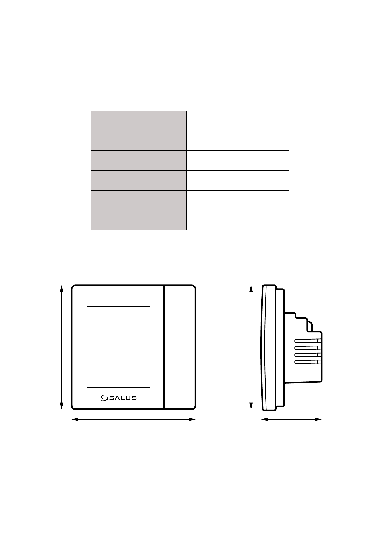
83
Power supply 230 V AC 50 Hz
Temperature range 5 - 35°C
Temperature measurement accuracy 0.5°C
SPAN ±0.25°C or ±0.5°C
RF ZigBee 2,4 GHz
Dimensions [mm] 86 x 86 x 42
The VS10WRF/VS10BRF thermostat requires no special maintenance. Periodically, the outer casing can be wiped clean using a dry cloth (please DO
NOT use solvents, polishes, detergents or abrasive cleaners, as these can damage the thermostat). There are no user serviceable parts within the unit; any
servicing or repairs could only be carried out by Salus Controls or their appointed agents.
12. Cleaning and Maintenance
13. Technical Informations
86 mm 42 mm
86 mm 86 mm

84
14. Warranty
SALUS Controls warrants that this product will be free from any defect in materials or workmanship, and shall perform in accordance with its specication,
for a period of ve years from the date of installation. SALUS Controls sole liability for breach of this warranty will be (at its option) to repair or replace the
defective product.

86
IMPORTER:
SALUS Controls Plc
Units 8-10 Northfield Business Park
Forge Way, Parkgate
Rotherham
S60 1SD
United Kingdom
www.saluscontrols.com
SALUS Controls is a member of the Computime Group.
Maintaining a
policy of continuous product development SALUS Controls plc reserve the right to change
specification, design and materials of products listed in this brochure without prior notice.
Issued: 16 VII 2020
Version: 6