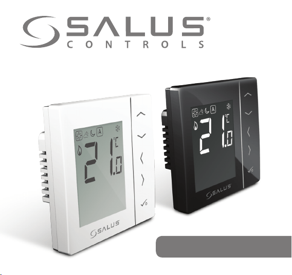
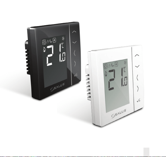
Digital Thermostat
Models: VS35W and VS35B
INSTALLER / USER MANUAL
02 VS35W and VS35B Installer / User Manual
Contents
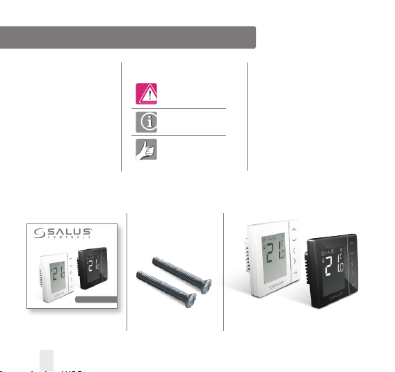
VS35
1 x Installer / User manual
Digital Thermostat
Models: VS35W and VS35B
INSTALLER / USER MANUAL
Fixing screws
Contents
Box Contents
Introduction
Product Compliance
Installation
User Guide
Parameter Settings
Installers Notes
Warranty
Box Contents
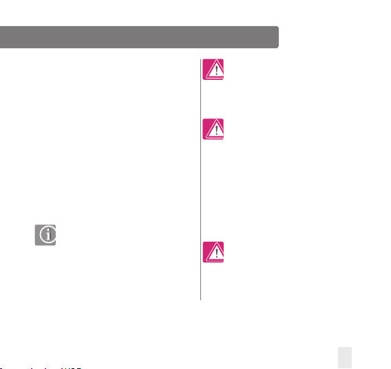
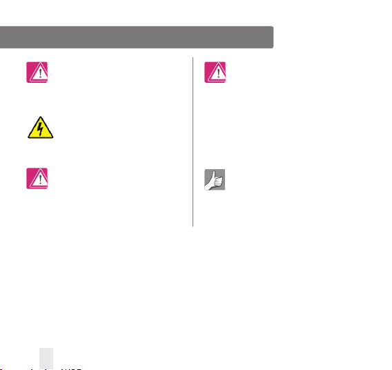
Icons used in this manual:
Safety
Important info
Your benefit
For latest PDF installation
guide please go to www.
salus-controls.com
Product Compliance & Safety Information
INTRODUCTION
Thank you for purchasing the room thermostat
VS35. The VS35 is a 230V digital thermostat
which offers simple temperature control of your
heating system.
By purchasing the VS35 you have decided on
a digital room thermostat which allows you to
adjust surface heating appliances individually,
such as underfloor, wall or panel heating.
A clear energy saving is possible by reducing
temp.
Product Compliance
This product is CE compliant and meets the
following EC Directives: 2014/30/EU, 2014/35/
EU and 2011/65/EU
Safety Information
Use in accordance with the regulations.
The VS35 is to be used for room
control of hot water heating systems
inside the house.
Installation
This product must be fitted by a competent
person, and installation must comply with the
guidance, standards and regulations applicable
to the city, country or state where the product
is installed. Failure to comply with the
requirements of the relevant guidance,
standards and regulations could lead to injury,
death or prosecution.
Always isolate the AC mains supply
before installing or working on any components
that require 230V AC 50Hz supply.
We hope you enjoy this product...
VS35W and VS35B Installer / User Manual 03
Product Compliance & Safety Information
Sources of danger
The thermostat must be disconnected from mains
supply before removing the cover.
230V AC
Emergency
Switch off the voltage to the indivdual thermostat
wring centre or complete system.
Installer parameter settings
The VS35 is equipped
with installer parameter section.
This must only be entered
by the installer or competent
person. Changing these parameters
can have a serious effect on
your heating system. See page 41.
For the installer
Please enter any parameter
changes in the installer notes section.
04 VS35W and VS35B Installer / User Manual
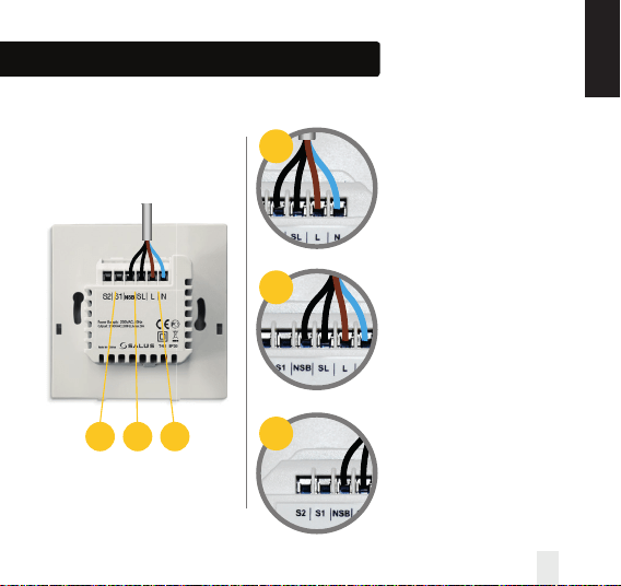
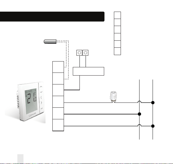
Installation – Terminal Connections
Understanding your terminal connections
Rear of VS35
Power Terminals 230 Vac
Used for supplying power to the
unit and switched output.
NSB (Night Set Back) Connection
Used for a 230V input from other
thermostats. See page 8.
Sensor Terminals S1, S2 (Optional)
Can be used for external AIR
or Floor sensor.
SL N L
Zone 1
Example
- - + +
VS35W
SL N L
Zone 1
Example
- - + +
SL N L
Zone 1
Example
- - + +
SL N L
Zone 1
Example
- - + +
1
3
3 2 1
2
VS35W and VS35B Installer / User Manual 05
INSTALLATION
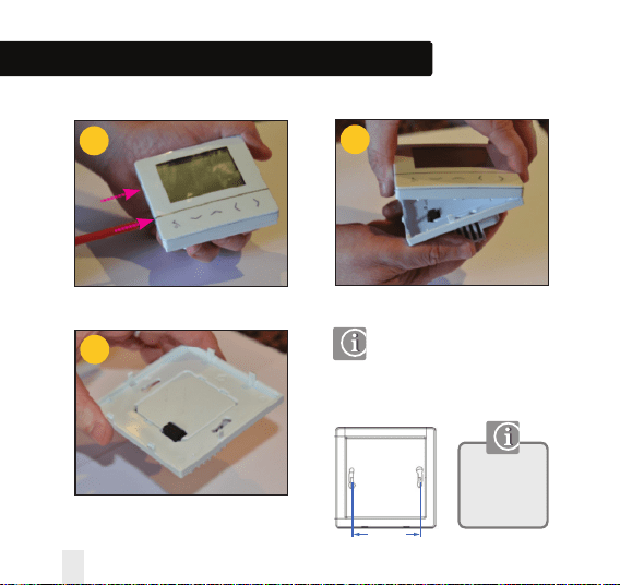
Installation – Thermostat Mounting
1
3
2
60mm
Wall Mounting
For wall mounting, mark and
mount the rear case to the wall.
The VS35 is suitable for wall boxes
with a centre hole distance of : 60mm
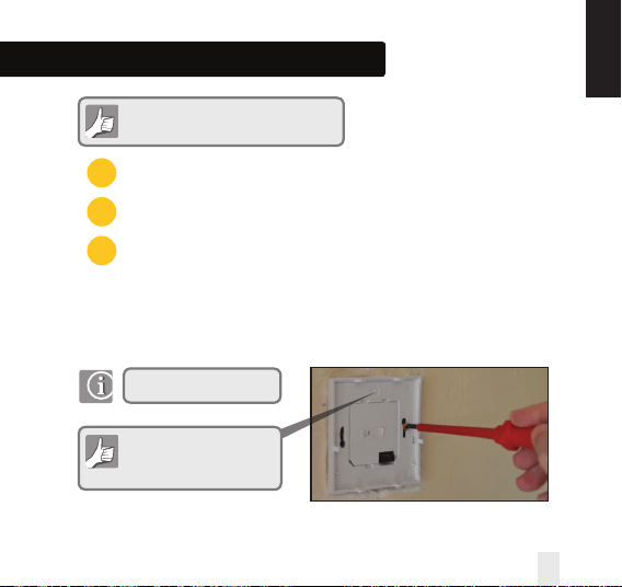
Gently remove front housing.
06 VS35W and VS35B Installer / User Manual
Gently remove front housing.
Only for flush
mounting boxes
with horizontal
fixing holes.
Installation – Thermostat Mounting
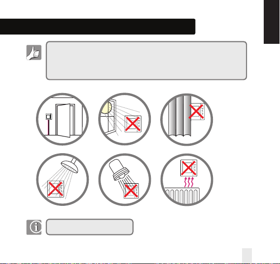
Not to be positioned on an exterior wall.
For your benefit symbol
To ensure trouble free operation and efficient control. the room thermostat Nea
is best positioned behind a door and at 130cm from the floor.
(Pic)
Do not position the thermostat:
1. Near any heat source (pics)
2. Behind curtains(pic)
3. Direct Sunlight(pic)
4. In a bathroom or area of high humidity(pic)
Info symbol
· Not to be positioned on exterior wall
· Do not install the remote sensor (if applicable) in an empty tube
· Only the temperature at the position of remote sensor (if applicable) is measured
130cm
130cm
Mounting position and installation
To ensure trouble free operation and efficient control, the VS35 room thermostat is best
positioned in a draft free area, and at 130cm from the floor. Do not position the thermostat near
any heat source, behind curtains, direct sunlight or an area of high humidity.
VS35W and VS35B Installer / User Manual 07
INSTALLATION
08 VS35W and VS35B Installer / User Manual
S2
S1
NSB
SL
L
N
S2
S1
NSB
SL
L
N
Sensor Terminal (optional)
Sensor Terminal (optional)
Night set back input
Load (Thermal Actuators)
Live 230V AC 50Hz
Neutral
L N
Wiring Centre
Thermal
Actuator
Optional SALUS
Sensor
Installation – Terminal Connections
L N
NSB from other
thermostats
Input
Installation – Terminal Connections
Power Terminals
NSB (Night Set Back) Connection
Sensor Terminals (if applicable)
You are ready to secure the rear housing to the wall box
Check that the wiring is completed for:
1
2
3
Please use the screws provided
Ensure the orientation
arrow is pointing upwards.
VS35W and VS35B Installer / User Manual 09
INSTALLATION
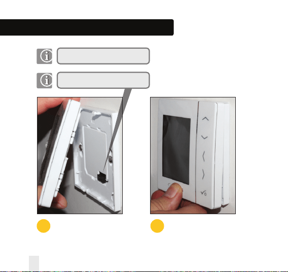
Installation – Thermostat Mounting
1
Fit the front housing to the rear housing
Align the front housing
at the top edge.
2
Lightly press until you
hear a positive click.
Ensure the pin connections are aligned
10 VS35W and VS35B Installer / User Manual
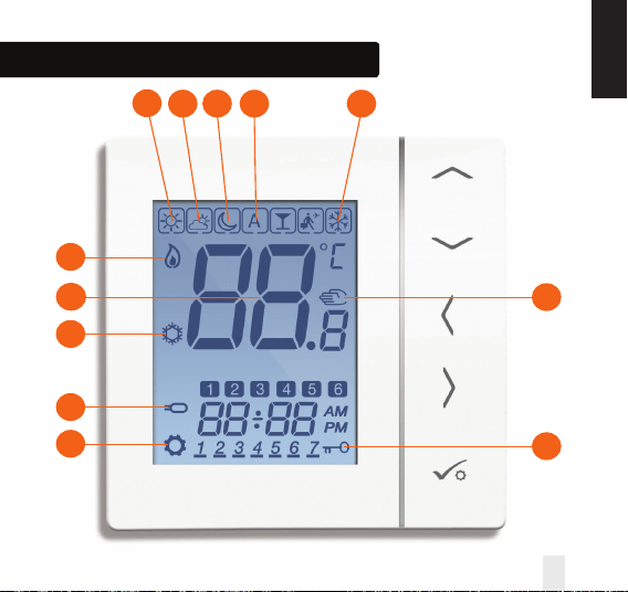
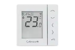
Installation – LCD Graphics
1
2 3 4 7
6
7
9
10
8
12
11
VS35W and VS35B Installer / User Manual 11
INSTALLATION
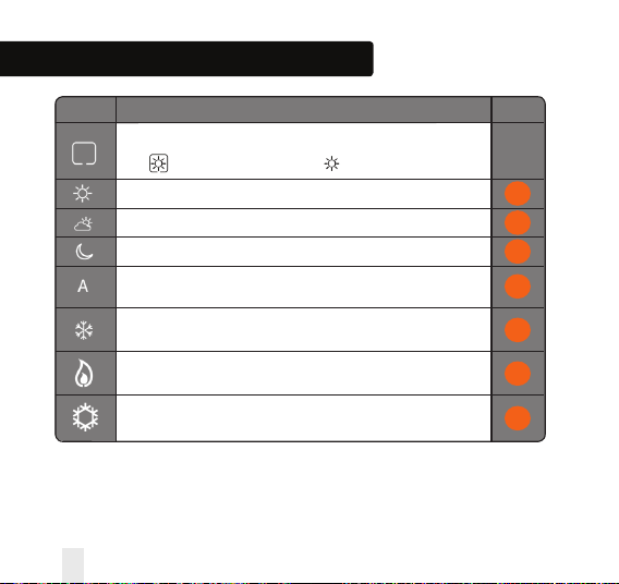
ICON FUNCTION
BOX means to select the mode
e.g. means the current setpoint is Hi temp, means the Hi temp is not selected.
Sunny: Hi comfortable temperature.
Cloudy: Middle comfortable temperature.
Moon: Low comfortable temperature.
Programmable thermostat Program mode indicator: Indicates program is
running, Auto On or Auto Off. For group thermostat this indicates that it is a member of a group.
Frost protection indicator:
Frost protection is active, not available in cooling mode (if applicable).
Heat indicator:
Indicates heat is required.
Cool mode indicator:
Indicates cooling is required (if applicable).
Installation – LCD Graphics
1
2
3
4
5
12 VS35W and VS35B Installer / User Manual
6
7
Installation – LCD Graphics
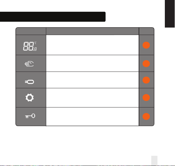
ICON FUNCTION
Temperature indicator:
Display the room temperature.
Display the set-temp.
Also used to show the other information.
Temporary manual override indicator:
If the set temperature is changed when in program mode,
the hand will appear until the next program start time.
8
9
VS35W and VS35B Installer / User Manual 13
INSTALLATION
Floor sensor probe indicator:
Show only when Air + Floor sensor is connected.
Setting indicator:
Indicates the unit is in setting mode when program setting.
Indicate’s the manual mode.
Keylock indicator:
Shows that keys are inactive.
10
11
12
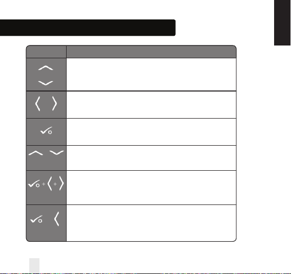
Installation – User Interface
KEY FUNCTION
1. Increase or decrease setpoint temperature.
2. Increase or decrease Day, Clock, Timer, Party and Holiday.
3. Select installer parameter value.
1. Mode selection.
2. Long press to return to home display without saving.
3. Short press to return to the previous screen when it is in user/installer setting mode.
1. OK key: Short press to confirm selection.
2. Long press to save and exit.
3. Long press to enter the user settings.
Lock/Unlock.
Enter Installer parameter settings.
Test mode.
OR
+
5 SECONDS
+ +
5 SECONDS
5 SECONDS
+
OR
INSTALLATION
14 VS35W and VS35B Installer / User Manual
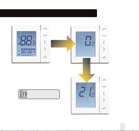
Installation – First Power Up
2 Seconds
2 Seconds
Software Version
Version will change from
unit to unit.
VS35W and VS35B Installer / User Manual 15
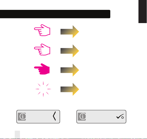
Installation - Graphics Key
Press once
Press x amount of times
Hold for five seconds
Flashing
xx
Short press to save and
long press to save and exit
Short press to back up
INSTALLATION
16 VS35W and VS35B Installer / User Manual
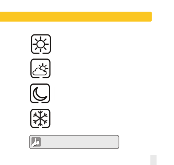
User Guide – Understanding Temperature Levels - Heating
Highest Temperature typically used for
early morning and early evening.
Typically 20 Deg C
Mid Temperature typically used for times of
day when you are active around the home.
Typically 19 Deg C
Lower Temperature typically used for
unoccupied or sleep times.
Typically 17 Deg C for UFH or 15 Deg C for radiators
Frost Temperature typically used for
periods of long absence or holidays.
Typically 5 Deg
Your thermostat comes preset for the above temperatures.
These can be adjusted.
VS35W and VS35B Installer / User Manual 17
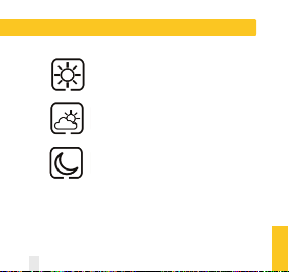
User Guide - Understanding Temperature Levels - Cooling
Occupied Temperature. Typically 22ºC
Unoccupied Temperature Typically 40ºC
This avoids cooling being active when the property is unoccupied.
Evening Temperature Typically 26ºC
USER GUIDE
18 VS35W and VS35B Installer / User Manual
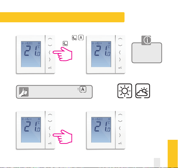
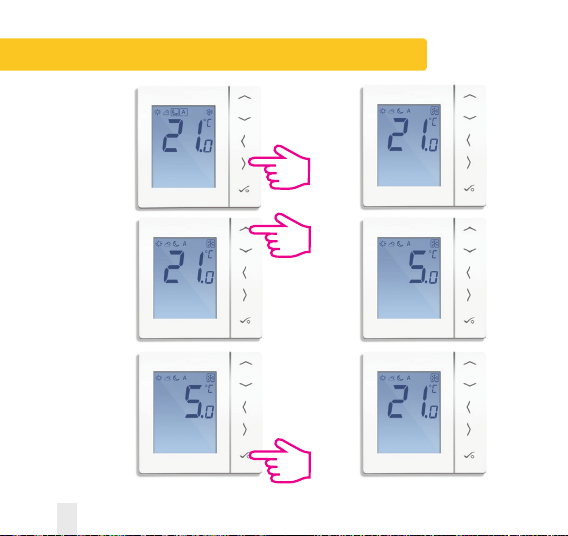
User Guide - Permanent Override
To cancel permanent override select
See below.
Use the up or down
arrow key to view
your set temperature.
Move from
to
Repeat for if required
Setting permanent low temperature
USER GUIDE
VS35W and VS35B Installer / User Manual 19
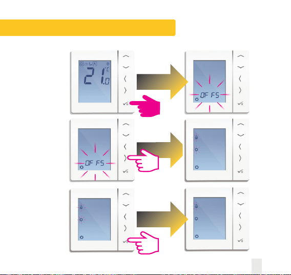
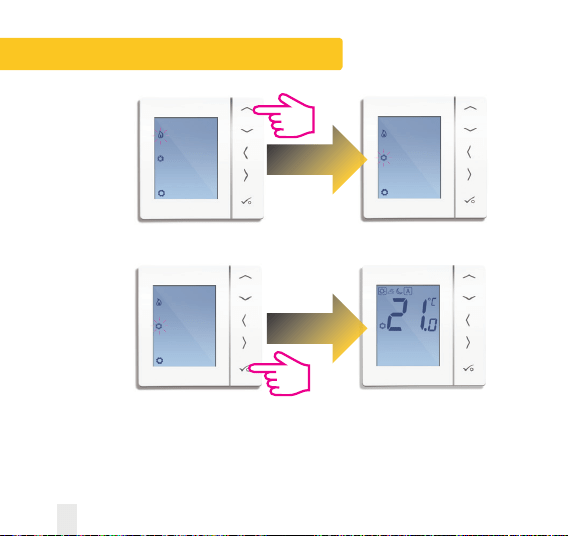
User Guide - Frost Protection
Use the right arrow
to select the frost
mode.
Use the up arrow
to select the
frost protection
temperature.
Press tick to confirm
the temperature
that it has been
set to.
20 VS35W and VS35B Installer / User Manual
User Guide - Heat cool change over
VS35W and VS35B Installer / User Manual 21
User Guide - Heat cool change over
22 VS35W and VS35B Installer / User Manual
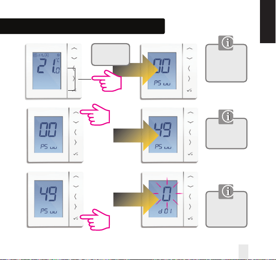
Installation - Entering Device Menu
If you need to
change device
parameters follow
the steps below.
Must only be
entered by the
installer.
This is the first
screen of the
device menu.
Press all
three buttons
simultaneously.
INSTALLATION
VS35W and VS35B Installer / User Manual 23
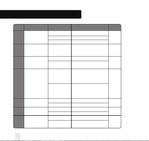
Installation - Device Parameters
DX FUNCTION SYSTEM SETTING DEFINITION DEFAULT
D01 Heating 0 Pulse Width Modulation
Control 1 On-Off 0.5 Deg C +/- 0.25 Deg C 0
2 On-Off 1.0 Deg C +/- 0.5 Deg C
D02 Room -3.0 to 3.0 Temperature Offset from
Temperature Deg C Measured Temperature to 0 Deg C
Offset Compensate for any error
D03 Sensor probe or 0 Sensor stat not Connected
Cylinder thermostat 1 Sensor stat Connected 0
connection
D04 Sensor probe 0 D03 must be set to 1 then
used as air sensor external sensor be used as
or floor sensor Air sensor. There will be no
internal temp measurement
0
1 D03 must be set to 1 then
external sensor used for floor
protection. Internal temp is
measured by stat
D05 Cooling Control 1 On-Off 0.5 Deg C +/- 0.25 Deg C
2
2 On-Off 1.0 Deg C +/- 0.5 Deg C
D06 Actuator type 0 NO Normally Open
1
1 NC Normally Closed
D07 Valve protection 0 Disable
1
1 Enable
24 VS35W and VS35B Installer / User Manual
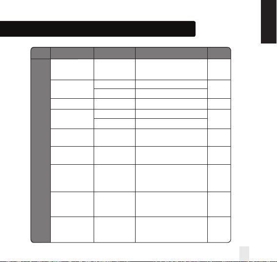
Installation - Device Parameters continued
DX FUNCTION SYSTEM SETTING DEFINITION DEFAULT
D08 Frost Set point 5-17 Deg C Required Temperature for frost 5 Deg
Temperature protection and holiday mode
D09 Hour Format 0 12
1
1 24
D10 N/A N/A N/A N/A
D11 Daylight Saving 0 OFF
1
Time (DST) 1 ON
D12 Heating Set point
5-35 Deg C
Maximum temp that can
35 Deg C
Limit be set for heating
D13 Cooling Set point
5-40 Deg C
Maximum temp that can
5 Deg C
Limit be set for Cooling
D14 Floor sensor High Output relay will be switched off
Limit Temperature 6-45 Deg C when temp is reached for 27 Deg C
floor protection
D15 Floor sensor Low Output relay will be switched on
Limit Temperature 6-45 Deg C when temp is reached for 10 Deg C
floor protection
D16 Floor sensor Limit Output relay will be switched off
for cooling 6-45 Deg C when temp is reached for 6 Deg C
floor protection
INSTALLATION
VS35W and VS35B Installer / User Manual 25
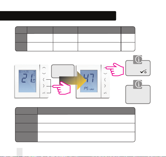
Installation - Device Parameters continued
DX FUNCTION SYSTEM SETTING DEFINITION DEFAULT
D17
D18
Preset program
selection
1-5 Select 1-5 of the default programs 1
Heat/Cool mode
selection
0 or 1
0: heating mode
1: cooling mode
0
Press all
three buttons
simultaneously.
Enter Number 47
and press
ERROR DESCRIPTION
Maximum/Minimum Floor Temp Reached
Broken Floor Sensor
Floor Sensor Short Circuit
Must only be
entered by the
installer.
Reset to factory settings
Err02
Err03
Err04
26 VS35W and VS35B Installer / User Manual
ERROR CODE
Installation - Technical Detail
INSTALLATION
Model VS35W/B
Type Digital room thermostat designed for 230V AC applications
Modes Frost
NSB 230V Input
Override Permanent
Frost Protection 5ºC Adjustable
Power Source 230V AC 50Hz
Rating 3 Amp
Temperature Scale 5 to 35ºC, tolerance 0.5ºC
Heat/Cool Local changeover
Sensor Air or floor protection.
Device Parameters See page 24 for full list of functions
Operating Temperature 0 to 50ºC
Storage Temperature -20 to 60ºC
VS35W and VS35B Installer / User Manual 27
Installation - Notes
28 VS35W and VS35B Installer / User Manual
Installation - Notes
VS35W and VS35B Installer / User Manual 29
SALUS Controls warrants that this product will be free from any defect in materials or workmanship, and shall
perform in accordance with its specification, for a period of five years from the date of installation. SALUS
Controls sole liability for breach of this warranty will be (at its option) to repair or replace the defective product.
Customer Name: .............................................................................................................................
Customer Address: ..........................................................................................................................
............................................................................... Post Code: .....................................................
Tel No: ........................................................ Email: .........................................................................
Engineers Company: .......................................................................................................................
Tel No: ......................................................... Email: ........................................................................
Installation Date: ...........................................................................................................................
Engineers Name: ............................................................................................................................
Engineers Signature: .....................................................................................................................
Warranty
30 VS35W and VS35B Installer / User Manual
VS35W and VS35B Installer / User Manual 31
Digital Thermostat
Models: VS35W and VS35B
www.saluscontrols.com
SALUS Controls plc
SALUS House
Dodworth Business Park South,
Whinby Road,
Dodworth, Barnsley S75 3SP, UK.
SALES:
T: +44 (0) 1226 323961
TECHNICAL: T: +44 (0) 1226 323961
Issue Date: April 2014
Maintaining a policy of continuous product development SALUS Controls plc reserve the right to
change specification, design and materials of products listed in this brochure without prior notice.
SALUS Controls is a member of the Computime Group
00086/2