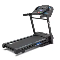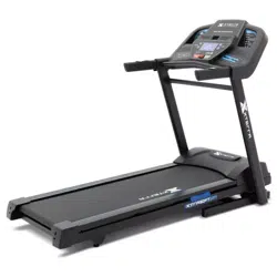

TR95H
HIKER TREADMILL
Scan to quickly and easily
register your new XTERRA
Fitness machine.
If you require assistance or are
experiencing issues with your
XTERRA Machine, please contact
customer care for additional help.
1-800-258-8511
questions@xterratness.com
Online Support
Warranty Registration
TR95H_OwnersManual_195813_20240119


2
Table of Contents
Product Registration .........................................................3
Warning / Safety Instructions
Product Labels .....................................................................4
Safety Instructions .............................................................5
Electrical Safety .................................................................. 6
Grounding & Location Requirements ........................... 7
Parts and Assembly
Parts of your Unit ............................................................... 8
Parts Included ..................................................................... 9
Assembly .............................................................................. 11
Setting Up Your Unit ........................................................16
Safety Key ............................................................................ 17
Technology and Features
About Your Machine ........................................................18
Console Screen - Overview ............................................ 19
Console Features .............................................................20
Quick Start ......................................................................... 22
Programs
Programs ............................................................................ 23
Preset Programs ............................................................... 24
Wearing the Chest Strap ................................................ 39
Heart Rate Exertion ........................................................40
Maintenance
Maintenance & Care ........................................................ 42
Deck Lubrication ..............................................................46
Belt & Deck ......................................................................... 47
Exploded View Diagram ................................................48
Warranty & Troubleshooting
Warranty ............................................................................ 49
Troubleshooting ............................................................... 52

3
PRODUCT REGISTRATION
WARRANTY REGISTRATION
Use your smartphone to scan the QR code
above to quickly and easily register your
new XTERRA Fitness machine.
You can also go to xterratness.com/
warranty under the Support tab to
register online.
Congratulations on your new Hiker Treadmill, and welcome to the
XTERRA Fitness family!
Thank you for your purchase of this quality unit from XTERRA
Fitness. Your new unit was manufactured by one of the leading
tness manufacturers in the world and is backed by one of the most
comprehensive warranties available. XTERRA Fitness will do all we can
to make your ownership experience as pleasant as possible for many
years to come.
If you have questions, or if parts are missing or damaged, or you require
customer service, call (870) 336-4286. Please have your model number
and serial number handy when you call.
Please take a moment at this time to record the name of the dealer,
their telephone number, and the date of purchase below to make any
future, needed contact easy. We appreciate your support and we will
always remember that you are the reason that we are in business.
Serial
Number
Date of
Purchase
Dealer /
Place of
Purchase
Version: 3.0
Revision: 01/19/24
4
SERIAL NUMBER
(870) 336-4286
X XXXXXXXXX X
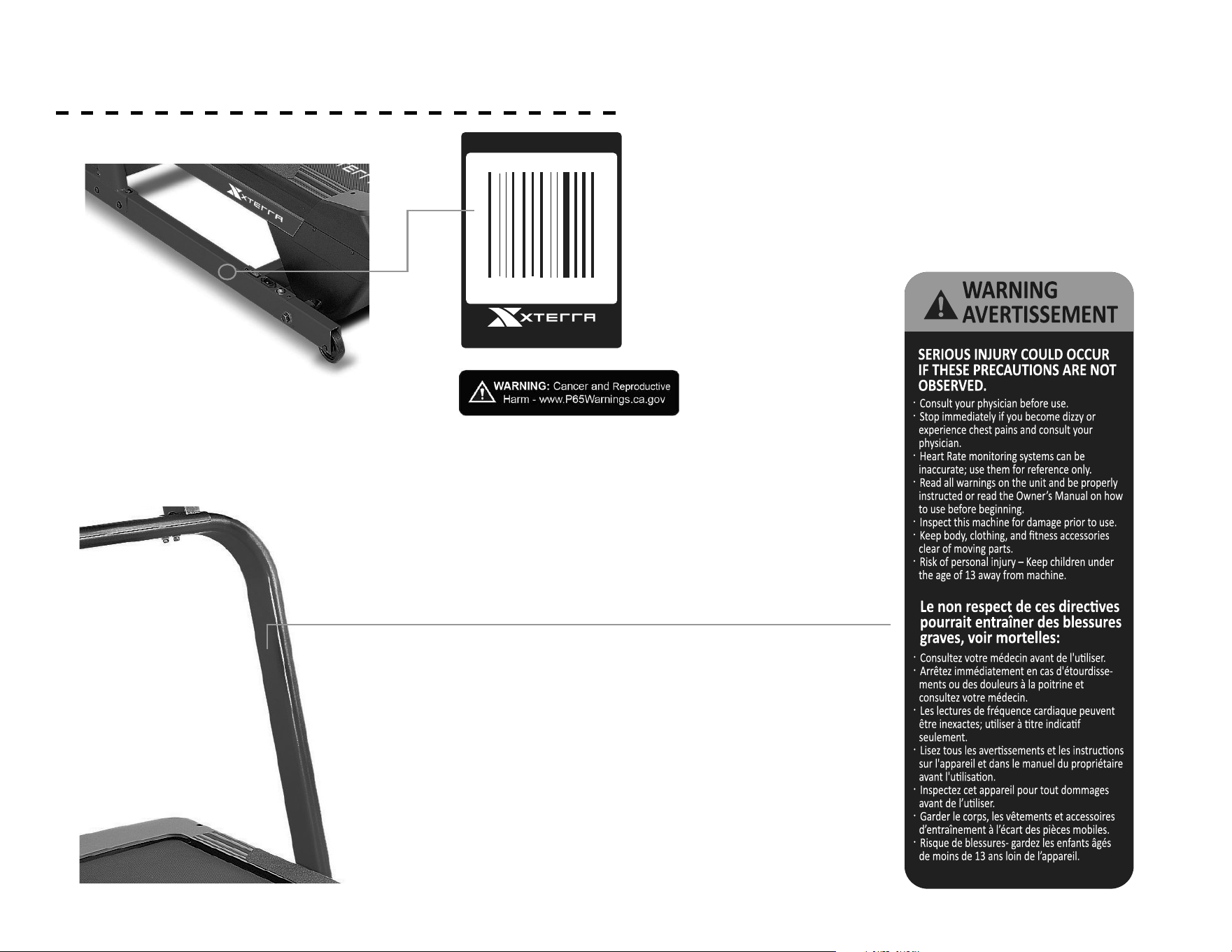
PRODUCT LABELS
SERIAL NUMBER STICKER
This sticker will be found on the frame near the power switch.
Please record the number below the barcode for the purpose
of registering your Hiker Treadmill’s warranty.
PROPOSITION 65 WARNING
This sticker will be found on the frame near
the power switch. The State of California
requires us to inform you that this unit was
manufactured using chemicals that could cause
harm with improper use.
SAFETY WARNING STICKER
This sticker will be found on the interior side of
your Hiker Treadmill’s upright. The same warn-
ing can be found in this manual. Please read and
be aware of the precautions before operating
your unit.

5
SAFETY INSTRUCTIONS
When using an electrical appliance, basic precautions should always be
followed, including the following:
Read all instructions before using this appliance.
DANGER - To reduce the risk of electric shock:
Always unplug this appliance from the electrical outlet immediately after
using and before cleaning.
WARNING - To reduce the risk of burns, re electric shock, or
injury to persons:
1. An appliance should never be left unattended when plugged in. Un-
plug from outlet when not in use, and before putting on or taking o
parts.
2. Do not operate under blanket or pillow. Excessive heating can occur
and cause re, electric shock, or injury to persons.
3. This exercise equipment is not intended for use by persons with re-
duced physical, sensory or mental capabilities, or lack of experience
and knowledge.
4. Use this appliance only for its intended use as described in this manu-
al. Do not use attachments not recommended by the manufacturer.
5. Never operate this appliance if it has a damaged cord or plug, if it is
not working properly, if it has been dropped or damaged, or dropped
into water. Return the appliance to a service center for examination
and repair.
6. Do not carry this appliance by supply cord or use cord as a handle.
7. Keep the cord away from heated surfaces.
8. Never operate the appliance with the air openings blocked. Keep the
air openings free of lint, hair, and the like.
9. Never drop or insert any object into any opening.
10. Do not use outdoors.
11. Do not operate where aerosol (spray) products are being use or where oxy-
gen is being administered.
12. Connect this appliance to a properly grounded outlet only. See Grounding
Instructions.
13. The appliance is intended for household use.
14. To disconnect, turn all controls to the o position, then remove the plug
from the outlet.
15. Do not operate equipment on deeply padded, plush or shag carpet. Damage
to both carpet and equipment may result.
16. Before beginning this or any exercise program, consult a physician. This is
especially important for persons over the age of 35 or persons with pre-ex-
isting health conditions.
17. Keep hands away from all moving parts.
18. The pulse sensors are not medical devices. Various factors, including the
user’s movement, may aect the accuracy of heart rate readings. The pulse
sensors are intended only as exercise aids in determining heart rate trends in
general.
19. Do not attempt to use your equipment for any purpose other than for the
purpose it is intended.
20. Do not operate tablet or laptop when you are running, walking or climbing at
high speed.
21. Wear proper shoes. High heels, dress shoes, sandals or bare feet are not
suitable for use on your equipment. Quality athletic shoes are recommended
to avoid leg fatigue.
22. User Weight Limit: 300 lbs.
!
!
Please ensure that you review and adhere to the user
weight restrictions and power requirements of your
new machine. Failure to do so may result in serious
injury or damage to your machine.
!

6
ELECTRICAL SAFETY
WARNING!
Route the power cord away from any moving part of the unit
including the elevation mechanism and transport wheels.
NEVER remove any cover without rst disconnecting AC
power. If voltage varies by ten percent (10%) or more, the
performance of your unit may be aected. Such conditions
are not covered under your warranty. If you suspect the
voltage is low, contact your local power company or a
licensed electrician for proper testing.
NEVER expose this unit to rain or moisture. This product
is NOT designed for use outdoors, near a pool or spa, or
in any other high humidity environment. The temperature
specication is 40 degrees C, and humidity is 95%, non-
condensing (no water drops forming on surfaces).
Circuit breakers: Avoid AFCI/GFCI circuit breakers if
possible. These breakers may trip occasionally during
exercise because of the high inrush currents of the unit drive
electronics and motor. This is an issue that aects all unit
brands. New laws in your area may require these breakers.
If you do have these breakers and outlets in your home,
and are experiencing nuisance tripping, you should check if
there are any other devices plugged into the same circuit.
Some examples of devices that may also cause tripping are
uorescent lights with electronic ballasts, coee maker,
space heater, hair drier.
Optimally the unit should be the only device plugged into the
circuit. Our units have surge suppressors built in to help avoid
nuisance tripping. We have tested several AFCI/GFCI breakers
and outlets with our products. Brands we have tested are: Eaton
(Cutler Hammer Series), Leviton (Smart lock pro) and Schneider
Electric (Canadian home series). These breakers do not trip in our
testing, when connected to our units, as long as no other devices
are plugged into the same circuit.
NEVER operate this unit without reading and completely
understanding the results of any operational change you
request from the computer.
Understand that changes in speed and incline do not occur
immediately. Set your desired work level on the computer
console and release the adjustment key. The computer will obey
the command gradually.
NEVER use your unit during an electrical storm. Surges may
occur in your household power supply that could damage unit
components. Unplug the unit during an
electrical storm as a precaution.
Use caution while participating in other activities while walking
on your unit; such as watching television, reading, etc. These
distractions may cause you to lose balance which may result in
serious injury.
Do not use excessive pressure on console control keys. They are
precision set to function properly with little nger pressure.
!
7
GROUNDING & LOCATION REQUIREMENTS
This product must be grounded. If the unit should malfunction or
breakdown, grounding provides a path of least resistance for electric
current, reducing the risk of electric shock. This product is equipped with a
cord having an equipment-grounding plug. The plug must be plugged into
an appropriate outlet that is properly installed and grounded in accordance
with all local codes and ordinances.
DANGER - Improper connection of the equipment-grounding
conductor can result in a risk of electric shock. Check with a qualied
electrician or serviceman if you are in doubt as to whether the product is
properly grounded. Do not modify the plug provided with the product if it
will not t the outlet; have a proper outlet installed by a qualied electrician.
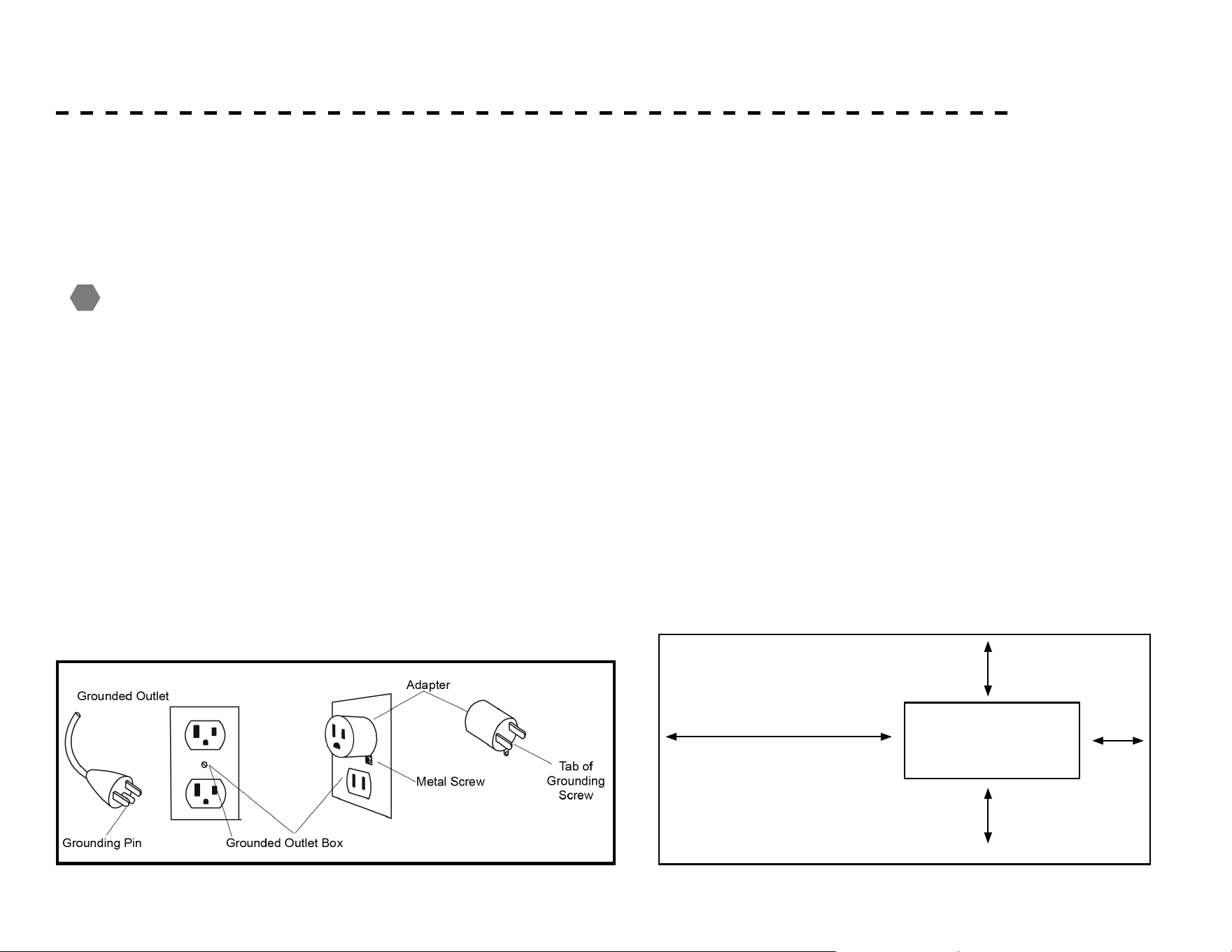
This product is for use on a nominal 120-volt circuit, and has a grounding
plug that looks like the plug illustrated below. A temporary adapter that
looks like the adapter illustrated below may be used to connect this plug
to a 2-pole receptacle as shown below if a properly grounded outlet is
not available. The temporary adapter should be used only until a properly
grounded outlet, (shown below) can be installed by a qualied electrician.
The green colored rigid ear-lug, or the like, extending from the adapter,
must be connected to a permanent ground such as a properly grounded
outlet box cover. Whenever the adapter is used, it must be held in place by a
metal screw.
!
After assembling your Hiker Treadmill, you’ll need to make sure
you’ve installed it in a safe area.
• We recommend that you leave an area of at least 20in on the
front, and sides of your machine. The front of the unit is where
the motor is located.
• We recommend that you leave an area of at least 6ft behind the
Hiker Treadmill.
• Install your Hiker Treadmill in an area where children and pets
cannot access it.
• Always keep the area around your Hiker Treadmill clear of furni-
ture, exercise equipment and other debris.
• Do not install your Hiker Treadmill on deeply padded, plush, or
shag carpet.
20in
20in
20in
6ft
Location Requirements
8
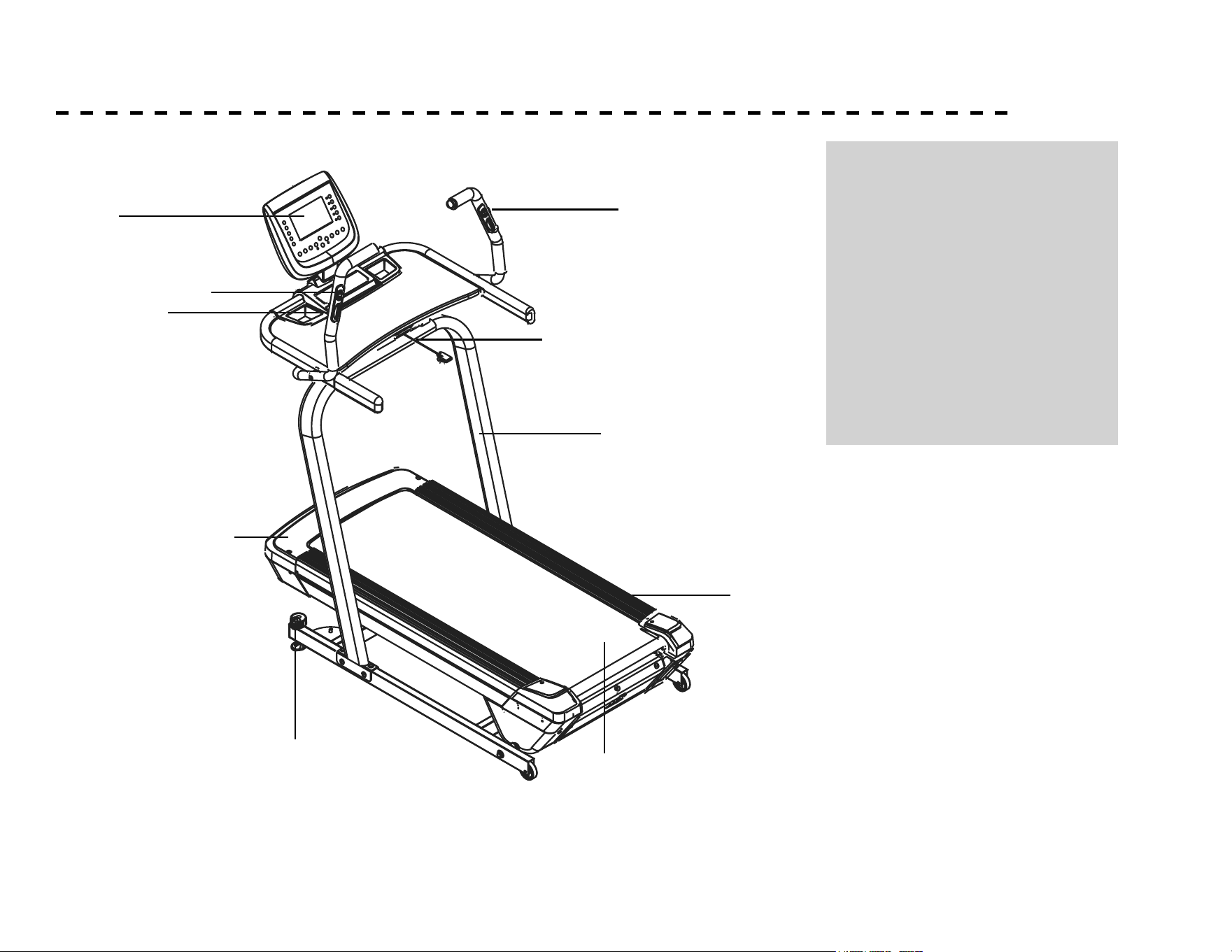
PARTS OF YOUR UNIT
A
B
J
C
I
D
E
F
G
H
A. LCD Window
B. Hand Pulse Grips
C. Safety Key
D. Upright
E. Side Rails
F. Belt
G. Leveler
H. Motor
I. Remote Speed Buttons
J. Remote Incline Buttons
9
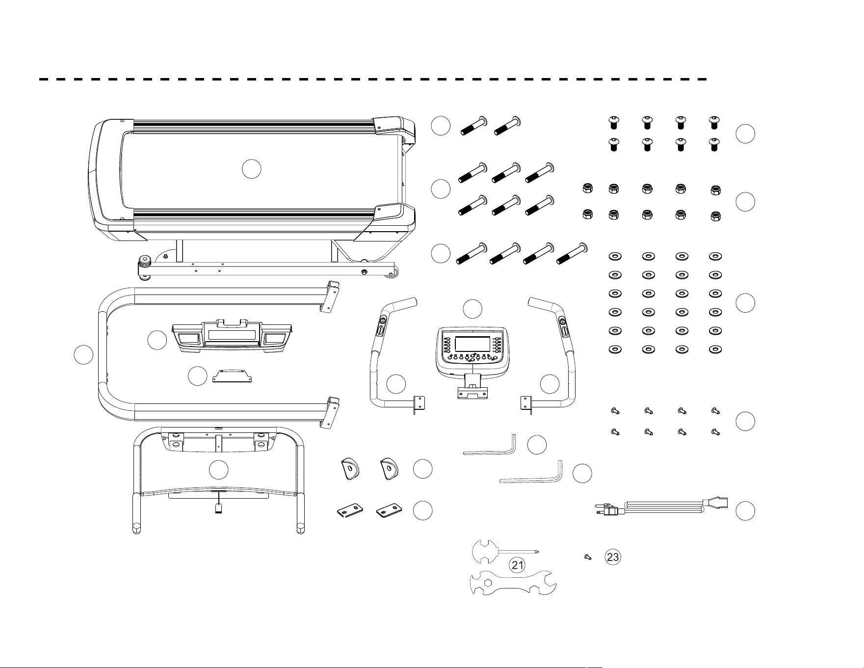
PARTS INCLUDED
ASSEMBLY PARTS LIST
5
JJKKEEXXEERR 333377
1
2
3
4
5
6
7
8
10
11
12
1
1
1
1
1
1
1
1
1
2
4
13
14
15
16
17
18
19
20
21
22
8
6
24
13
2
2
1
1
1
1
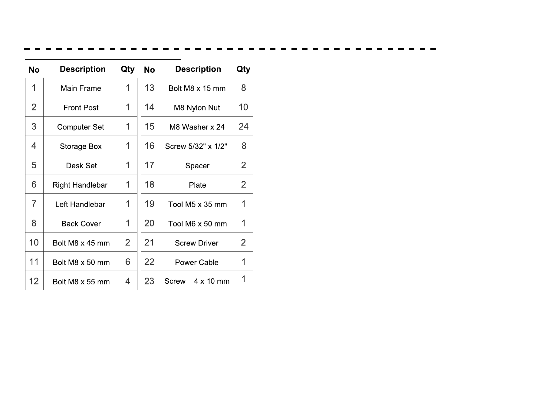
Main Frame
Front Post
Computer Set
Storage Box
Desk Set
Right Handlebar
Left Handlebar
Back Cover
Bolt M8 x 45 mm
Bolt M8 x 50 mm
Bolt M8 x 55 mm
Bolt M8 x 15 mm
M8 Nylon Nut
M8 Washer x 24
Screw 5/32" x 1/2"
Spacer
Plate
Tool M5 x 35 mm
Tool M6 x 50 mm
Screw Driver
Power Cable
1
2
5
4
8
7
3
6
12
11
10
14
13
16
15
18
17
20
19
22
21
No
DescriptionQtyDescriptionQty
No
ASSEMBLY PARTS LIST
5
JJKKEEXXEERR 333377
1
2
3
4
5
6
7
8
10
11
12
1
1
1
1
1
1
1
1
1
2
4
13
14
15
16
17
18
19
20
21
22
8
6
24
13
2
2
1
1
1
1
Main Frame
Front Post
Computer Set
Storage Box
Desk Set
Right Handlebar
Left Handlebar
Back Cover
Bolt M8 x 45 mm
Bolt M8 x 50 mm
Bolt M8 x 55 mm
Bolt M8 x 15 mm
M8 Nylon Nut
M8 Washer x 24
Screw 5/32" x 1/2"
Spacer
Plate
Tool M5 x 35 mm
Tool M6 x 50 mm
Screw Driver
Power Cable
1
2
5
4
8
7
3
6
12
11
10
14
13
16
15
18
17
20
19
22
21
No
DescriptionQtyDescriptionQty
No
CORRECTION
P10 - PARTS INCLUDED
P13 -
ASSEMBLY - CONTINUED
Ø
P9 - PARTS INCLUDED
10
PARTS INCLUDED
CORRECTION
P10 - PARTS INCLUDED
P13 -
ASSEMBLY - CONTINUED
Ø
P9 - PARTS INCLUDED
11
ASSEMBLY
1. Please note the end with Wire (98) out from Front Post
(2) is for the right side Main Frame (1). Ask one person to
help holding Front Post (2), and well connect Wire (57)
out from Main Frame (1) and Wire (89) out from Front
Post (2). Tuck the connector back into the hole on Main
Frame (1).
Be careful not to damage the wire or the connector.
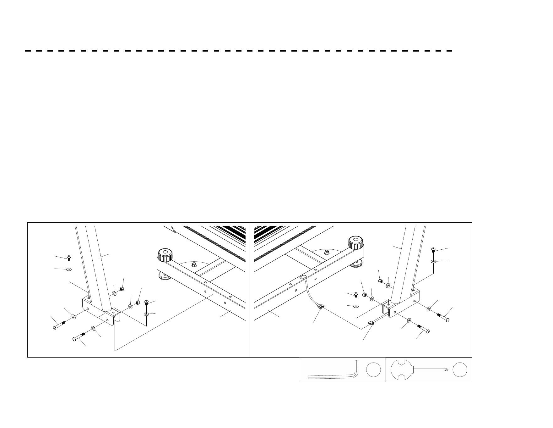
2. Mount Front Post (2) on each right & left side of Main
Frame (1) and secure the post with parts (11, 15, 14 & 13)
as shown.
6
ASSEMBLY INSTRUCTIONS
Step 1.
Please note the end with Wire (98) out from Front Post (2) is for the right side Main Frame (1).
Ask one person to help holding Front Post (2), and well connect Wire (57) out from Main Frame (1)
and Wire (89) out from Front Post (2). Tuck the connector back into the hole on Main Frame (1).
Be careful not to damage the wire or the connector.
Step 2.
Mount Front Post (2) on each right & left side of Main Frame (1) and secure the post with
parts (11, 15, 14 & 13) as shown.
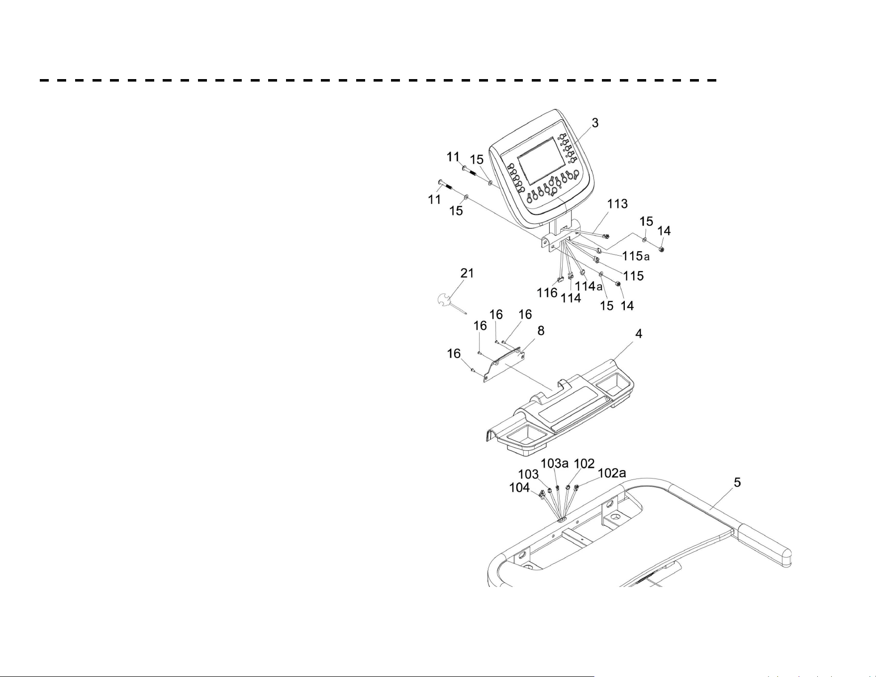
Step 3.
Loose cable tie to separate 3 Wires (102, 103 , 104) out from
Desk Set (5), and 3 Wires (116, 114, 114) out from Computer
Set (3). Well connect the 6 wires. (Connect 104 to 116; 103 to
1
14 and 102 to 115; make sure no mismatch.) Tuck the
connectors one by one back into the hole on Desk Set (5).
Do not damage the wires or the connectors.
Step 4.
Install Computer Set (3) on Desk Set (5), and secure it with
parts (11, 15 & 14) in order as shown.
13
15
15
11
15
11
15
13
14
15
14
15
1
2
98
57
15
13
14
15
14
15
15
11
15
11
15
13
2
1
5
102
103
104
335 / 655
DESK SET
115
114
116
3
15
11
14
15
11
15
113
14
15
Step 5.
Mount Storage Box (4) on the top of Desk Set (5).
Put on the Back Cover (8), and lock it with parts (16).
Step 6.
16
4
8
16
16
16
21
20
5
102
103
104
21
12
ASSEMBLY - CONTINUED
3. Loose cable tie to separate 5 Wires (102, 102a,
103 , 103a, 104) out from Desk Set (5), and
5 Wires (114, 114a, 115, 115a, 116) out from
Computer Set (3). Well connect the 10 wires.
(Connect 104 to 116; 103 to 114, 103a to 114a;
and 102 to 115, and 102a to 115a; make sure no
mismatch.) Tuck the connectors one by one back
into the hole on Desk Set (5).
Do not damage the wires or the connectors.
4. Install Computer Set (3) on Desk Set (5), and
secure it with parts (11, 15 & 14) in order as
shown.
5. Mount Storage Box (4) on the top of Desk Set
(5).
6. Put on the Back Cover (8), and lock it with parts
(16).
ASSEMBLY - CONTINUED
5 (102, 102a ,
103, 103a , 104) 5
(114, 114a, 115, 115a, 116)
10
103a to 114a;
102 to 115; 102a to 115a ch.)
o the hole
6
ASSEMBLY INSTRUCTIONS
Step 1.
Please note the end with Wire (98) out from Front Post (2) is for the right side Main Frame (1).
Ask one person to help holding Front Post (2), and well connect Wire (57) out from Main Frame (1)
and Wire (89) out from Front Post (2). Tuck the connector back into the hole on Main Frame (1).
Be careful not to damage the wire or the connector.
Step 2.
Mount Front Post (2) on each right & left side of Main Frame (1) and secure the post with
parts (11, 15, 14 & 13) as shown.
13
15
15
11
15
11
15
13
14
15
14
15
1
2
98
57
15
13
14
15
14
15
15
11
15
11
15
13
2
1
5
102
103
104
335 / 655
DESK SET
20
21
13
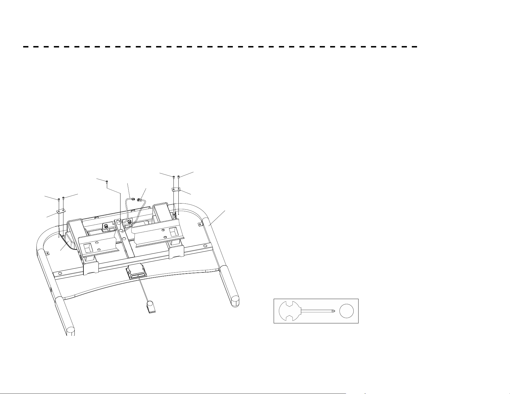
ASSEMBLY - CONTINUED
7. Use 2 Plates (18) and Screws (16) to x Storage Box (4)
on Desk Set (5) from underneath.
8.
Fix Storage Box (4) on Desk Set (5) with Screw (23) from
the hole underneath as shown. Connect Wire (113) out
from computer with Wire (110) out from Safety Key Box
(9) as shown.
16
16
16
16
18
18
5
4
113
16
110
2 1
23
14
ASSEMBLY - CONTINUED
116
5
98
12
12
12
12
2
15
15
15
15
14
14
14
14
Attach the assembled Desk Set to the
top of Front Post (2), firmly secure it
with parts (12, 14 & 15) as shown.
Be sure not to damage the wire or the
connector.
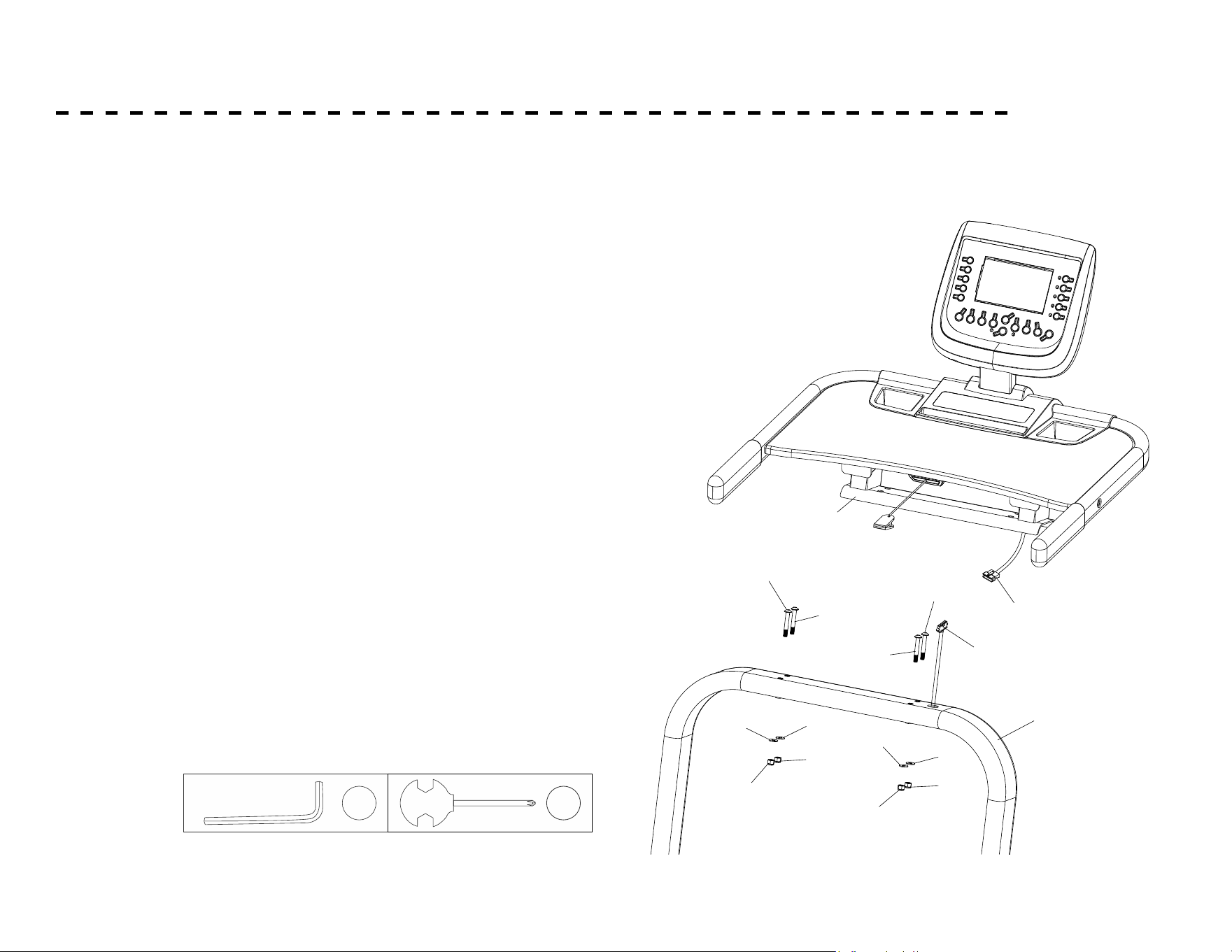
Step 11.
is as the drawing below.
Ask someone to hold the assembled
Desk Set (5) on the top of Front Post (2).
Well connect Wire (116) out From Desk
Set (5) with Wire (98) out from top of
Front Post (2). Tuck the connector back
into the hole on Front Post (2). Be sure
not to damage the wires or the
connector.
Step 10.
2 0
2 1
9. Ask someone to hold the assembled Desk Set (5) on the top of Front
Post (2). Connect the Wire (116) out from Desk Set (5) with the Wire
(98) out from top of Front Post (2). Tuck the connector back into
the hole on the Front Post (2). Be sure not to pinch the wires or the
connector.
10. Attach the assembled Desk Set to the top of Front Post (2), rmly
secure it with parts (12, 14 & 15) as shown. Be sure not to pinch the
wire or the connector.
15
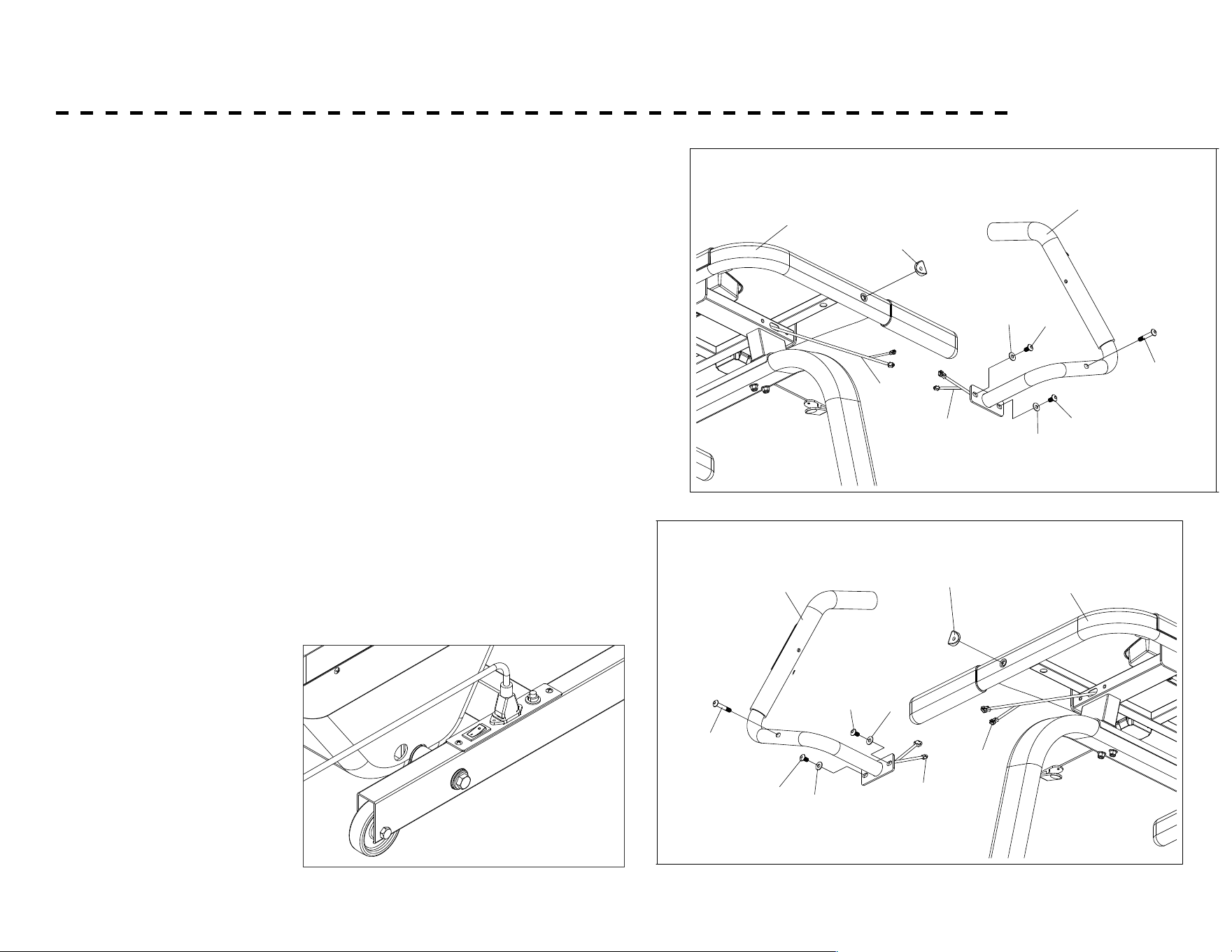
ASSEMBLY - CONTINUED
11. Ask someone to hold Right Handlebar (6), connect Wire (102) out
from assembled Desk Set with Wire (123) out from Right Handlebar
(6). Tuck the connector back into Right Handlebar (6).
Be sure not to damage the wire or the connector.
12. Attach the bottom end of Right Handlebar (6) to the right side of
Desk Set with Parts (13) & (15) as show, but do not tighten the bolts
yet.
13. Fix the middle section of Right Handlebar (6) onto the right side of
Desk Set and rmly secure it with parts (10 & 17). Now, tighten the
parts (13, 15) on Step 13 securely. Follow the same procedure to x
Left Handlebar (7) on the left side of Desk Set (5), and tighten the
bolts accordingly.
14. Plug in Power Cable (22) on the Main Switch located on the right
side of Main frame (1).
8
ASSEMBLY INSTRUCTIONS
123
102
13
15
10
6
5
17
13
15
103
119
13
15
13
15
10
17
7
5
LEFT
RIGHT
Fix the middle section of Right Handlebar(6) onto the right side of Desk Set and firmly secure it
with parts (10 & 17). Now, tighten the parts (13, 15) on Step 13 securely. Follow the same procedure
to fix Left Handlebar (7) on the left side of Desk Set (5), and tighten the bolts accordingly.
Step 14.
Attach the bottom end of Right Handlebar (6) to the right side of Desk Set with Parts (13) & (15)
as show, but do not tighten the bolts yet.
Step 13.
Ask someone to hold Right Handlebar (6), connect Wire (102) out from assembled Desk Set with
Wire (123) out from Right Handlebar (6). Tuck the connector back into Right Handlebar (6)
.
Be sure not to damage the wire or the connector.
Step 12.
Step 15.
Plug in Power Cable (22) on the Main Switch located on the
right side of Main frame (1).
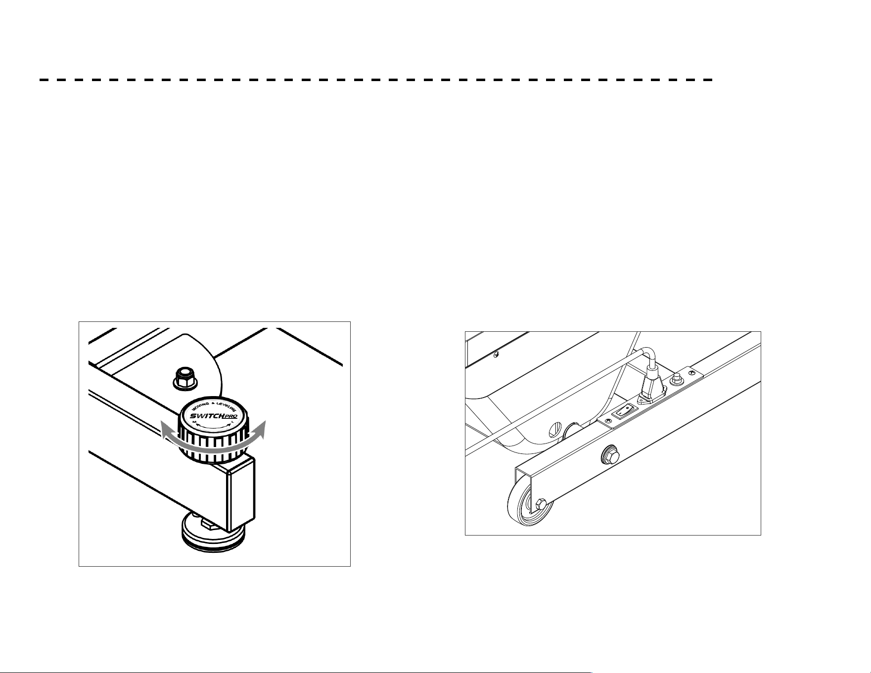
MOVING & LEVELING
Please note there are 2 SwitchPro knobs at the
front bottom of main frame.
1. Moving: Clockwise turn both knobs for moving
the machine
2. Leveling: Anti clockwise turn the knob to level
the frame for operation.
ML
8
ASSEMBLY INSTRUCTIONS
123
102
13
15
10
6
5
17
13
15
103
119
13
15
13
15
10
17
7
5
LEFT
RIGHT
Fix the middle section of Right Handlebar(6) onto the right side of Desk Set and firmly secure it
with parts (10 & 17). Now, tighten the parts (13, 15) on Step 13 securely. Follow the same procedure
to fix Left Handlebar (7) on the left side of Desk Set (5), and tighten the bolts accordingly.
Step 14.
Attach the bottom end of Right Handlebar (6) to the right side of Desk Set with Parts (13) & (15)
as show, but do not tighten the bolts yet.
Step 13.
Ask someone to hold Right Handlebar (6), connect Wire (102) out from assembled Desk Set with
Wire (123) out from Right Handlebar (6). Tuck the connector back into Right Handlebar (6)
.
Be sure not to damage the wire or the connector.
Step 12.
Step 15.
Plug in Power Cable (22) on the Main Switch located on the
right side of Main frame (1).
MOVING & LEVELING
Please note there are 2 SwitchPro knobs at the
front bottom of main frame.
1. Moving: Clockwise turn both knobs for moving
the machine
2. Leveling: Anti clockwise turn the knob to level
the frame for operation.
ML
16
SETTING UP YOUR HIKER TREADMILL
Moving and Leveling
Please note there are 2 SwitchPro knobs at the front bottom
of main frame.
1. Moving: To move the machine, turn both knobs clockwise
2. Leveling: to level the frame for operation, turn the knob
counterclockwise
Plugging in and Powering On
Power the unit on by plugging it into an appropriate wall
outlet, then turn on the power switch located at the front of
the Hiker Treadmill below the motor hood, Ensure that the
Safety Key is installed, as the Hiker Treadmill will not power
on without it.
When the power is turned on, all the lights on the display
will light up for a short time and the console will show the
software version.
The Hiker Treadmill will then enter idle mode, which is the
starting point for operation.
8
ASSEMBLY INSTRUCTIONS
123
102
13
15
10
6
5
17
13
15
103
119
13
15
13
15
10
17
7
5
LEFT
RIGHT
Fix the middle section of Right Handlebar(6) onto the right side of Desk Set and firmly secure it
with parts (10 & 17). Now, tighten the parts (13, 15) on Step 13 securely. Follow the same procedure
to fix Left Handlebar (7) on the left side of Desk Set (5), and tighten the bolts accordingly.
Step 14.
Attach the bottom end of Right Handlebar (6) to the right side of Desk Set with Parts (13) & (15)
as show, but do not tighten the bolts yet.
Step 13.
Ask someone to hold Right Handlebar (6), connect Wire (102) out from assembled Desk Set with
Wire (123) out from Right Handlebar (6). Tuck the connector back into Right Handlebar (6)
.
Be sure not to damage the wire or the connector.
Step 12.
Step 15.
Plug in Power Cable (22) on the Main Switch located on the
right side of Main frame (1).
MOVING & LEVELING
Please note there are 2 SwitchPro knobs at the
front bottom of main frame.
1. Moving: Clockwise turn both knobs for moving
the machine
2. Leveling: Anti clockwise turn the knob to level
the frame for operation.
ML
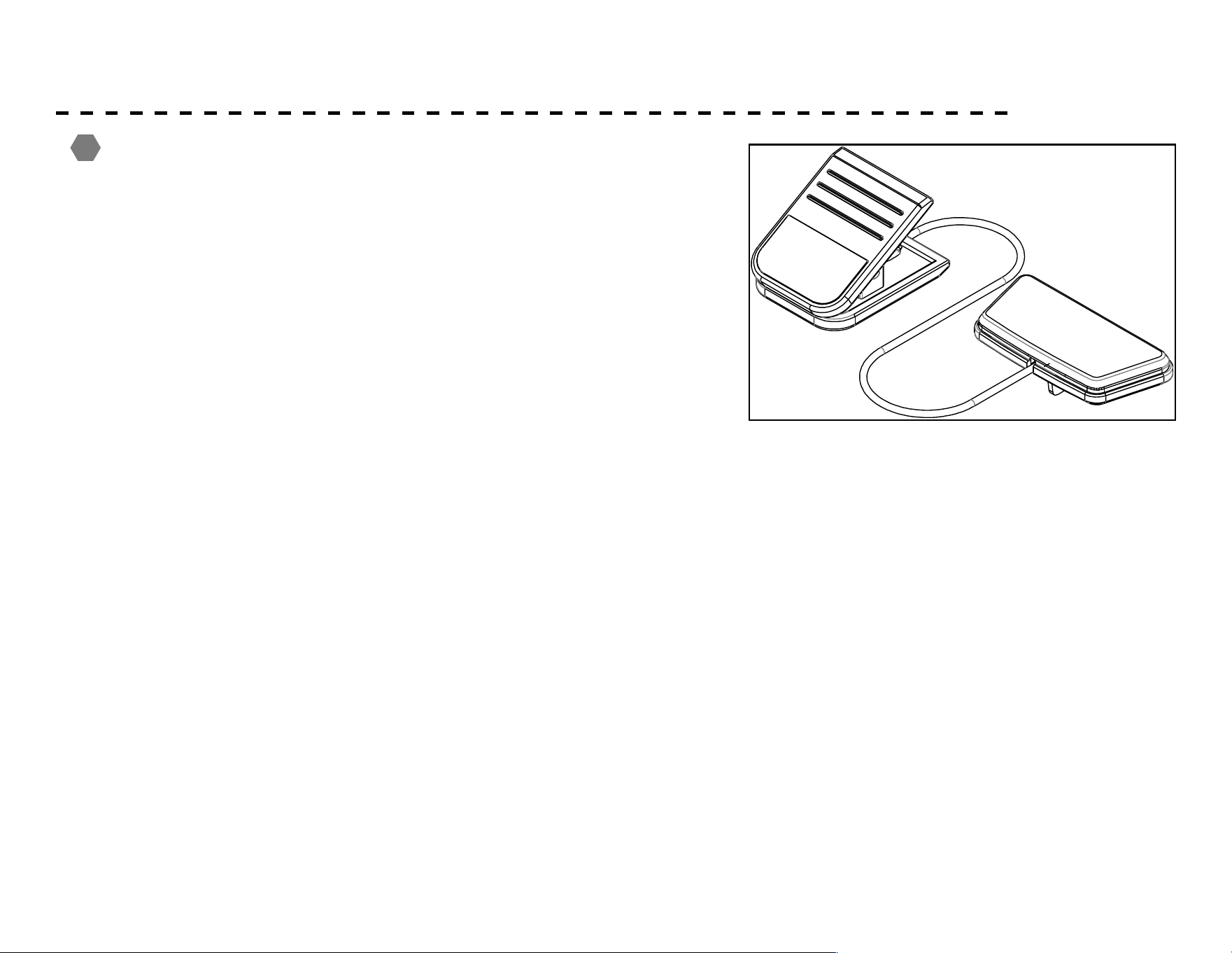
17
SAFETY KEY
A safety tether cord is provided with this unit.
It is a simple magnetic design that should be used at all times.
It is for your safety should you fall or move too far back on the
tread-belt.
Pulling this safety tether cord will stop tread-belt movement.
To Use:
1. Place the magnet into position on the round metal portion of
the console control head. Your unit will not start and operate
without this. Removing the magnet also secures the unit from
unauthorized use.
2. Fasten the plastic clip onto your clothing securely to ensure
good holding power. Note: The magnet has strong enough
power to minimize accidental, unexpected stopping. The clip
should be attached securely to make certain it does not come
o. Be familiar with its function and limitations. The unit
will stop, depending on speed, with a one to two step coast
anytime the magnet is pulled o the console. Use the Stop /
Pause switch in normal operation.
!

18
ABOUT YOUR MACHINE
Always use care and caution when operating your
machine. Follow instruction in this manual to ensure safe
operation and maintenance of your Hiker Treadmill
!
Be sure to follow XTERRA Fitness on your favorite social
media platforms to view and share the latest tness videos,
images, and news.
facebook.com/XterraFitness
www.instagram.com/XterraFitness
youtube.com/user/XterraFitnessOnline
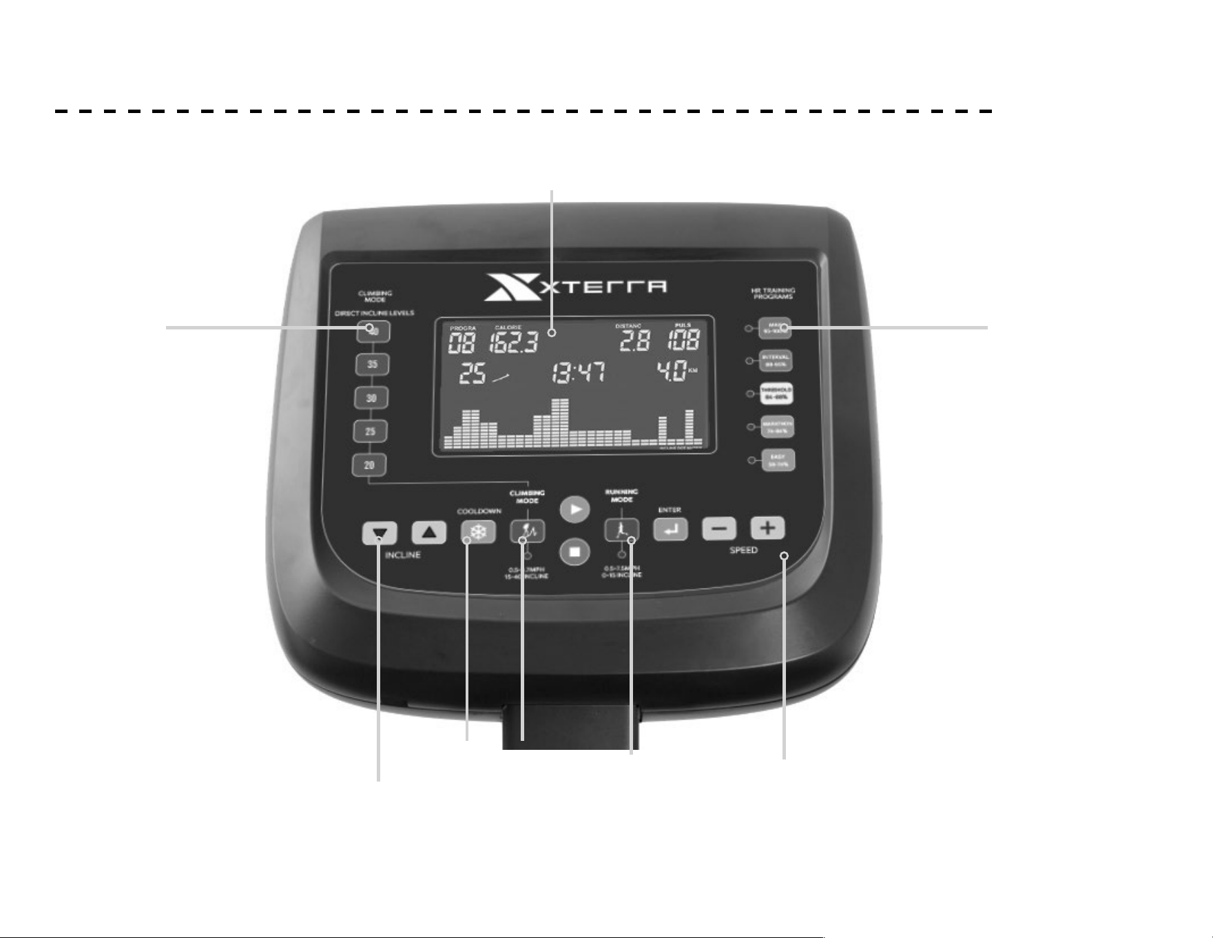
19
CONSOLE SCREEN - OVERVIEW
LCD Window
Speed
Buttons
HR Training
Programs
Direct Incline
Buttons
Incline Buttons
Climbing
Mode
Cooldown
Button
Running
Mode

20
CONSOLE FEATURES
SPEED / INCLINE RANGE:
• Running Mode: 0.8 ~ 12 kph/0.5-7.5 mph, Level 0 ~ 15
• Climbing Mode: 0.8 ~ 6 kph/0.5-3.7 mph, Level 15 ~ 40
PROGRAM:
• Running Mode:
• 12 preset with Dicult Level 1 - 3
• 3 targets (Time, Distance, Calories)
• HR (Max, Interval, Threshold, Marathon, Easy) / 0.5
mph – 6.2 mph, Level 0-15
• Fat
• Climbing Mode:
• 5 preset
• 3 targets (Time, Distance, Calories)
• HR (Max, Interval, Threshold, Marathon, Easy) / 0.5
mph– 2.5 mph, Level 15-40
• Fat
• Defaulted data: Gender – Male, Age – 30, Height – 67 in,
Weight – 154 lb, Time – 30 Minutes, Resting Heart Rate – 72
bpm, Target Distance – 1.0 mile, Target Calories – 10Kcal,
Target Time – 30 Minutes
FUNCTION DISPLAY:
1. PULSE window: (A) Heartbeat 0 ~ 200bpm
(B) Body Type 1 ~ 5
(C) RESTING HEART RATE.
2. CALORIES window: (A) Calories 10 ~ 999 Kcal
(B) Height 20 ~ 98 cm
3. STEP window: (A) Step count (B) BMR
4. DISTANCE window: (A) Distance 0 ~ 99.9 mile (B) FAT%
5. PROGRAM window: (A) Running Mode 1 ~ 12, Climbing Mode
1 ~ 5.
(B) BMI
(C) U0 ~ U3
6. GENDER window: Male / Female
7. INCLINE window: (A) Level 0 ~ 15 for Running mode, Level
15 ~ 40 for Climbing Mode
(B) Age 10 ~ 99 years old. Default setting:
30 years old
(C) Dicult Level 1 ~ 3
8. TIME window: 00:00 ~ 99:59
9. SPEED window: (A) Running Mode 0.8 ~ 12 kph, Climbing
Mode 0.8 ~ 6 kph
(0.5 – 7.5 mph / 0.5 – 3.7 mph)
(B) Weight 44 ~ 309 lb
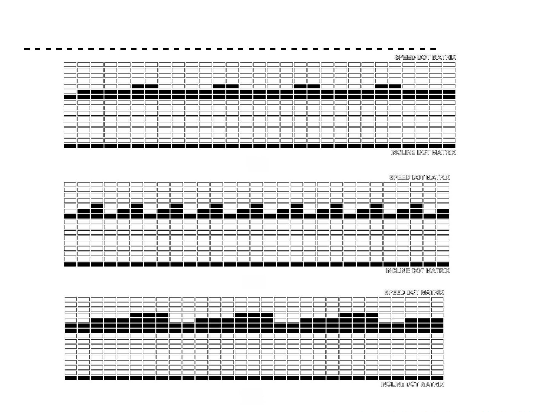
10. Speed Unit: KM or MILE (Default Setting KM)
11. Dot Matrix: 16 x29 Dot

21
CONSOLE FEATURES
BUTTON FUNCTION:
1. Direct Incline Buttons: Quick incline selection for Climbing mode.
2. INCLINE / : (A) Setting data
(B) Selecting preset program & level
(C) Adjusting incline.
(D) Choosing U0 ~ U3 to key in personal data. U0: To be keyed in data but no memory. U1, U2, & U3 are for memory
of 3 users. This data can be deleted by pressing and holding Enter for 3 seconds for re-input.
3. COOL DOWN : Press to lower down speed & incline instantly. Re-pressing will resume to original program.
4. Climbing mode : For climbing exercise
5. START : For starting the machine or waking up the sleeping mode
6. STOP : For temporary stopping the machine, pressing for 3 seconds, all system set to 0.
7. Running mode : For running exercise
8. ENTER : For conrming setting data
9. SPEED :
(A) Setting data
(B) Selecting preset program & level
(C)Adjusting speed.
10. Max, Interval, Threshold, Marathon, Easy: For Heart Rate training. Easy is the lowest, Max is the highest heart rate zone.
11. LAP: Each dot is 8 meters (0.00497 miles, one lap is 400 meters (.25 miles), 0 ~ 99 lap.
12. USB PORT: Located at the bottom left of the console for the charging of tablets and cell phones.

22
OPERATION & QUICK START
HOW TO OPERATE
To start operation, press either Running Mode or Climbing Mode button
OPERATION
After pressing Running or Climbing Mode button, press Start for quick start operation or press Incline to choose U0 - U3
to key in user data for program operation.
FOR QUICK START OPERATION
Press Start to start running. Press Incline Up/Down and Speed Up/Down to adjust incline (Level 0-15 for Running, Level
15-40 for Climbing) and speed (0.5 mph – 7.5 mph for Running, 0.5 mph – 3.7 mph for Climbing). Lap 00 appears on the
left and one dot ashes on the right side of LCD. One dot represents 8 meters (0.00497 miles), 1 circle represents 400m
(0.25 miles). When 00 jumps to 01, you have run 400 meters (0.25 mile).

23
PROGRAMS - TO SELECT AND START A PROGRAM
FOR PROGRAM OPERATION
1. Press Incline Up / Down to choose U0, U1, U2 or U3.
2. Press Enter, then press Speed Up/Down to key in gender, age, height, weight, and resting heart rate (RHR)
3. Press Enter to conrm
4. Press Start to begin or press Incline Up / Down or Speed Up / Down to choose either Preset, Target or HR program for operation.
PRESET PROGRAM OPERATION
1. Press Incline Up / Down or Speed Up/Down to choose P1 ~ P12 for Running (P1 ~ P5 for Climbing).
2. Press Enter, L1 ashes, press Incline Up /Down or Speed Up / Down to choose L1 ~ L3. (No diculty level adjustment for Climbing
mode)
3. Press Enter , default setting time 30 ashes. Press Incline Up / Down or Speed Up / Down to set desired workout time.
4. Press Start to start running
Please refer to Page 25 for preset program prole and data.
TARGET PROGRAM OPERATION
1. Press Incline Up/Down or Speed Up/Down to choose target distance, time or calories.
2. Press Enter then press Incline Up/Down or Speed Up/Down to set target data.
3. Press Start to start running.
HEART RATE (HR) PROGRAM OPERATION:
0.5 MPH – 6.2 MPH, LEVEL 0-15 FOR RUNNING / 0.5 MPH – 2.5 MPH, LEVEL 15-40 FOR CLIMBING)
1. Press Max, Interval, Threshold, Marathon, or Easy. LCD will show heart rate zone then Choose Program or Start.
2. Press Enter and Incline Up / Down or Speed Up / Down to set workout time.
3. Press Start to start running. Computer will detect to compare user’s heart rate and set heart rate to adjust speed and incline as
described on page 25.

24
PRESET PROGRAMS
1. For HR programs operation, wear a transmitter (sold
separately) or hold both hands on the pulse plates on both
handlebars to detect heartbeat.
2. If user's heart rate is lower than set target per detection,
speed will automatically increase 0.2km. When the speed
is at highest 10kph, but user's heart rate is still lower, then
incline will increase 1 level each time. When the speed is at
the highest 10km, and incline also at the highest level 40, but
user's heart rate is still lower than target heart rate, machine
will keep running following the highest speed and incline.
3. If user's heart rate is higher than set target per detection,
speed will automatically decrease 0.2km per time. When the
speed is at the lowest, but user's heart rate is still higher, then
incline will decrease 1 level each time. When the speed and
incline are at the lowest but user's heart rate is still higher
than target heart rate, machine will stop automatically.
4. If computer did not detect heartbeat for continuous 20
seconds, machine will stop and NO PULSE will show on the
console.
5. How to calculate heart rate zone:
6. How to accurately detect your RHR, Resting Heart Rate?
For reference: On the following day after resting day, after
getting up in the morning, supplement water of 250 ~ 300 cc,
then stand up to check your pulse for continuous 3 minutes to
get the most accurate Resting Heart Rate.
INTENSITY HRR (%)
Easy 59 - 74%
Marathon 74 - 84%
Threshold 84 - 88%
Interval 88 - 95%
Max 95 - 100%
Target Heart Rate Zone = (MHR - RHR) x HRR% + RHR
MHR (Max. Heart Rate) = 220 - age (For male)
226 - age (For female)
OTHER INSTRUCTIONS
1. 1. At any time, you may switch from Running Mode to Quick
Start of Climbing mode or from Climbing Mode to Running
Mode.
2. 2. Switching of Max, Interval, Threshold, Marathon, or Easy
a) Switching from low to high, speed and incline will remain the
same. HR will lift to the high level.
b) Switching from high to low, speed and incline will decrease
50%, HR will lower to low level.
3. If machine stops operation for 20 minutes, system will be reset.
4. When machine starts but no user runs on the deck for 3
minutes, machine will stop. 20 minutes after, whole system will
be reset.
5. In standby mode, if machine in not operated for 5 minutes,
computer screen will hibernate. Pres START button to wake up.

25
PRESET PROGRAMS
FAT program
1. Press Incline / or Speed / to choose FAT program.
2. Press Enter and then Start to start detecting. Around 12 seconds after, computer will show user's BMI, BMR, FAT% and BODY TYPE.
Since this machine is not for medical use, above data are only for reference and not for medical purpose.
Please note user has to hold both hands on the pulse plate. LCD Will show NO PULSE if computer could not detect user's heartbeat.
BMR (Basal Metabolic Rate)
Also called resting energy expenditure and is mostly determined by your genetic
makeup and body weight. It is the amount of energy required to maintain the
basal metabolism for a specied unit of time. The BMR resulting from our
machine based on 4 major factors: Sex, Height, Weight & Age. So when you key in
personal data, you will read your BMR in the computer.
You may also refer to below formula to calculate your BMR.
Male = 66 + (13.7 x Weight kg) + (5 x Height cm) - (6.8 x Age)
Female = 655 + (9.6 x weight kg) + (1.7 x Height cm) - (4.7 x Age)
BMI (Body Mass Index)
Get a numeric measure of BMI from your height and current weight to see if in healthy range. How
to calculate: If user is 60kgs weight, and 165cm tall, then BMI is 22. BMI 22 KG/(MxM) = 60 / (1.65 x
1.65)
Self evaluate if you fall within the target BMI range, and use exercise and control diet to reach or
stay within the target BMI range. Note: BMI does not dierentiate between muscle and fat mass.
1 Skinny
2 Underweight
3 Normal
4 Overweight
5 Extremely Overweight
Male
10 - 20% Normal
20 - 25% Overweight
Over 25% Extremely Overweight
Female
15 - 25% Normal
25 - 35% Overweight
Over 35% Extremely Overweight
Body Type: 1 - 5
Fat %
(BMI) (kg/m2)
Underweight BMI < 18.5
Normal
18.5 ≤ BMI < 25
Overweight
25 ≤ BMI < 30
Moderately Obese
30 ≤ BMI < 35
Severely Obese
35 ≤ BMI < 45
Very Severely Obese
40 ≤ BMI

26
PRESET PROGRAMS
COOL DOWN Mode:
1. After pressing Cool Down, incline will be lowered down to the
lowest level, and speed will lower down to 2kph/2.0mph.
2. Time, Calories, and Distance will keep accumulating.
3. Pressing Cool Down again will resume to the original program.
Notice about STEP count:
1. This machine oers function of walking training to detect and
accumulate total walking steps to incorporate user’s own count
goal.
2. Step count will start in 20 seconds after user steps on the ma-
chine and walks around 20 ~ 30 steps.
3. The accuracy will be less for those who walk lightly. The ac-
curacy for users over 100lbs who walk 1.2-3.7 mph with stable
steps will get accuracy of around 97%.
27
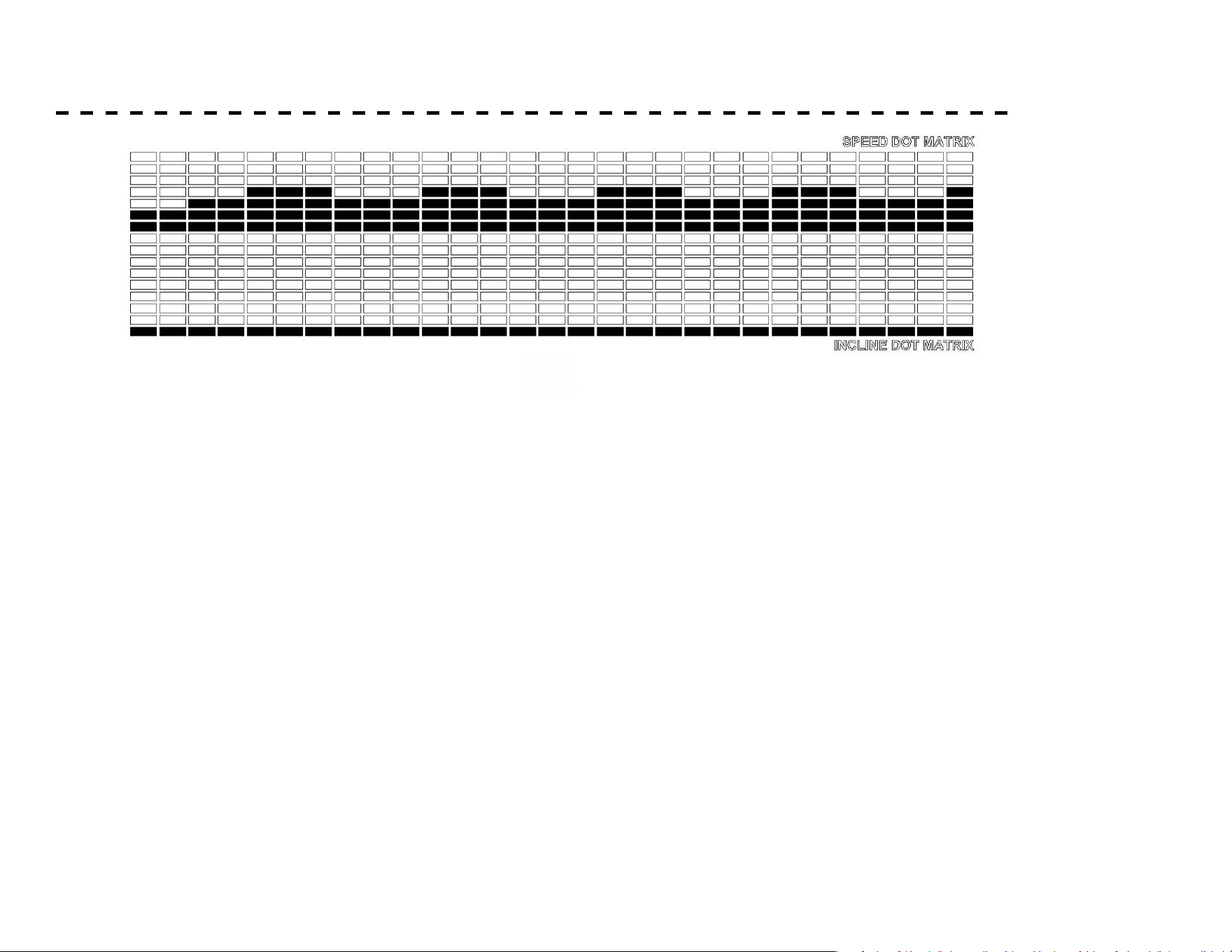
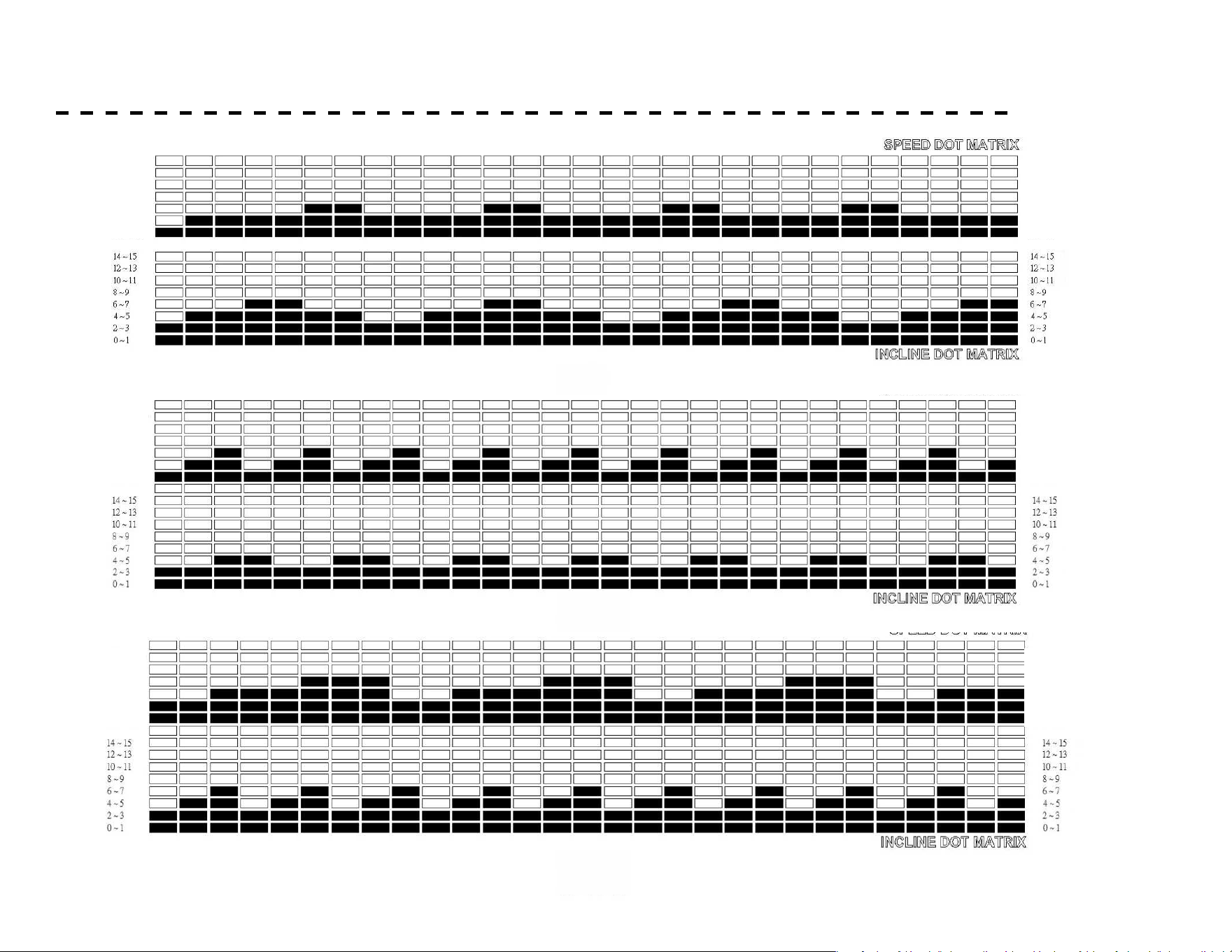
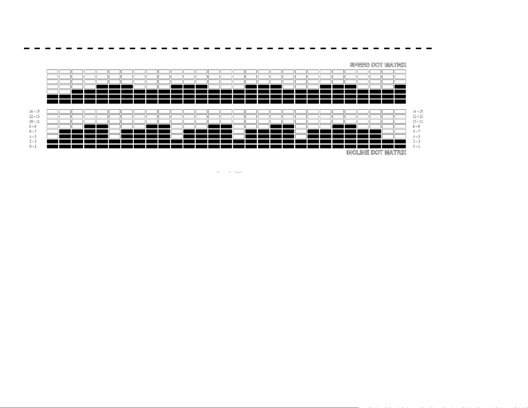
PRESET PROGRAMS - RUNNING MODE
15
P1 ~ P4 PROGRAM PROFILE
RUNNING MODE PRESET PROGRAM PROFILE AND DATA
P2
P1
P3
P4
15
P1 ~ P4 PROGRAM PROFILE
RUNNING MODE PRESET PROGRAM PROFILE AND DATA
P2
P1
P3
P4
15
P1 ~ P4 PROGRAM PROFILE
RUNNING MODE PRESET PROGRAM PROFILE AND DATA
P2
P1
P3
P4
6.1 - 7.5 MPH
4.1 - 6.0 MPH
2.1 - 4.0 MPH
0.5 - 2.0 MPH
14 - 15
12 - 13
10 - 11
8 - 9
6 - 7
4 - 5
2 - 3
0 - 1
6.1 - 7.5 MPH
4.1 - 6.0 MPH
2.1 - 4.0 MPH
0.5 - 2.0 MPH
14 - 15
12 - 13
10 - 11
8 - 9
6 - 7
4 - 5
2 - 3
0 - 1
6.1 - 7.5 MPH
4.1 - 6.0 MPH
2.1 - 4.0 MPH
0.5 - 2.0 MPH
14 - 15
12 - 13
10 - 11
8 - 9
6 - 7
4 - 5
2 - 3
0 - 1
6.1 - 7.5 MPH
4.1 - 6.0 MPH
2.1 - 4.0 MPH
0.5 - 2.0 MPH
14 - 15
12 - 13
10 - 11
8 - 9
6 - 7
4 - 5
2 - 3
0 - 1
6.1 - 7.5 MPH
4.1 - 6.0 MPH
2.1 - 4.0 MPH
0.5 - 2.0 MPH
14 - 15
12 - 13
10 - 11
8 - 9
6 - 7
4 - 5
2 - 3
0 - 1
6.1 - 7.5 MPH
4.1 - 6.0 MPH
2.1 - 4.0 MPH
0.5 - 2.0 MPH
14 - 15
12 - 13
10 - 11
8 - 9
6 - 7
4 - 5
2 - 3
0 - 1
28
PRESET PROGRAMS
15
P1 ~ P4 PROGRAM PROFILE
RUNNING MODE PRESET PROGRAM PROFILE AND DATA
P2
P1
P3
P4
6.1 - 7.5 MPH
4.1 - 6.0 MPH
2.1 - 4.0 MPH
0.5 - 2.0 MPH
14 - 15
12 - 13
10 - 11
8 - 9
6 - 7
4 - 5
2 - 3
0 - 1
6.1 - 7.5 MPH
4.1 - 6.0 MPH
2.1 - 4.0 MPH
0.5 - 2.0 MPH
14 - 15
12 - 13
10 - 11
8 - 9
6 - 7
4 - 5
2 - 3
0 - 1

29
Speed P1 P2 P3 P4
Level 1 Speed Incline Speed Incline Speed Incline Speed Incline
Interval 1 2.0 MPH 0 2.0 MPH 0 3.0 MPH 0 3.0 MPH 0
Interval 2 3.0 0 4.0 0 3.0 0 4.0 0
Interval 3 3.0 0 6.0 0 6.0 0 5.0 0
Interval 4 4.0 0 2.0 0 6.0 0 6.0 0
Interval 5 4.0 0 4.0 0 6.0 0 7.0 0
Interval 6 5.0 0 6.0 0 7.5 0 7.5 0
Interval 7 5.0 0 2.0 0 7.5 0 7.0 0
Interval 8 3.0 0 4.0 0 7.5 0 6.0 0
Interval 9 3.0 0 6.0 0 3.0 0 5.0 0
Interval 10 4.0 0 2.0 0 3.0 0 6.0 0
Interval 11 4.0 0 4.0 0 6.0 0 7.0 0
Interval 12 5.0 0 6.0 0 6.0 0 7.5 0
Interval 13 5.0 0 2.0 0 6.0 0 7.0 0
Interval 14 3.0 0 4.0 0 7.5 0 6.0 0
Interval 15 3.0 0 6.0 0 7.5 0 5.0 0
Interval 16 4.0 0 2.0 0 7.5 0 6.0 0
Interval 17 4.0 0 4.0 0 3.0 0 7.0 0
Interval 18 5.0 0 6.0 0 3.0 0 7.5 0
Interval 19 5.0 0 2.0 0 6.0 0 7.0 0
Interval 20 3.0 0 4.0 0 6.0 0 6.0 0
Interval 21 3.0 0 6.0 0 6.0 0 5.0 0
Interval 22 4.0 0 2.0 0 7.5 0 6.0 0
Interval 23 4.0 0 4.0 0 7.5 0 7.0 0
Interval 24 5.0 0 6.0 0 7.5 0 7.5 0
Interval 25 5.0 0 2.0 0 3.0 0 7.0 0
Interval 26 3.0 0 4.0 0 3.0 0 6.0 0
Interval 27 3.0 0 6.0 0 6.0 0 5.0 0
Interval 28 4.0 0 2.0 0 6.0 0 6.0 0
Interval 29 4.0 0 4.0 0 6.0 0 7.0 0
PRESET PROGRAMS
LEVEL 2 Based on LEVEL 1, but increases 2.0 MPH, no change on Incline.
LEVEL 3 Based on LEVEL 2, but increases 2.0 MPH, no change on Incline.
30
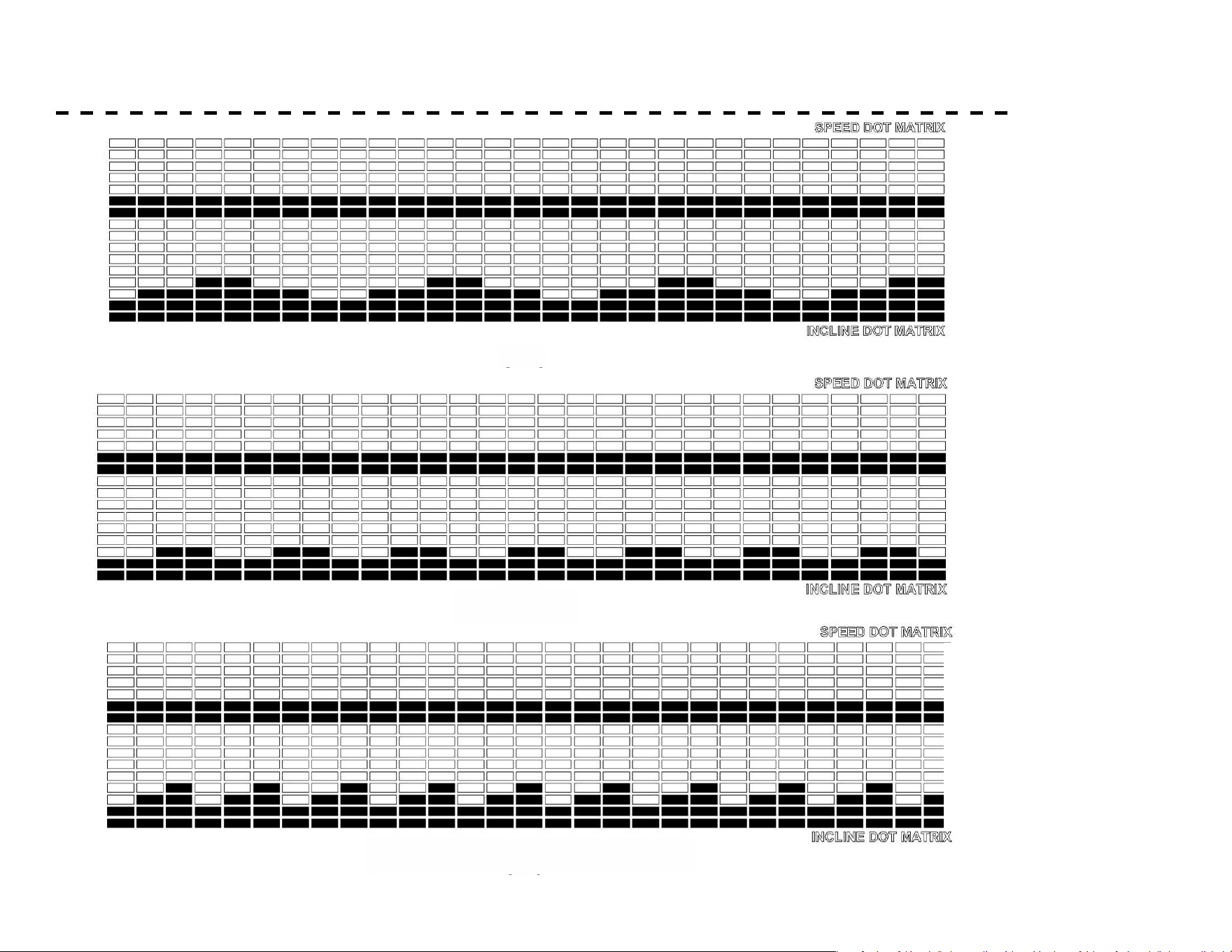
PRESET PROGRAMS
17
P 5 ~ P 8 PROGRAM PROFILE
P5
P6
P7
P8
17
P 5 ~ P 8 PROGRAM PROFILE
P5
P6
P7
P8
17
P 5 ~ P 8 PROGRAM PROFILE
P5
P6
P7
P8
6.1 - 7.5 MPH
4.1 - 6.0 MPH
2.1 - 4.0 MPH
0.5 - 2.0 MPH
14 - 15
12 - 13
10 - 11
8 - 9
6 - 7
4 - 5
2 - 3
0 - 1
6.1 - 7.5 MPH
4.1 - 6.0 MPH
2.1 - 4.0 MPH
0.5 - 2.0 MPH
14 - 15
12 - 13
10 - 11
8 - 9
6 - 7
4 - 5
2 - 3
0 - 1
6.1 - 7.5 MPH
4.1 - 6.0 MPH
2.1 - 4.0 MPH
0.5 - 2.0 MPH
14 - 15
12 - 13
10 - 11
8 - 9
6 - 7
4 - 5
2 - 3
0 - 1
6.1 - 7.5 MPH
4.1 - 6.0 MPH
2.1 - 4.0 MPH
0.5 - 2.0 MPH
14 - 15
12 - 13
10 - 11
8 - 9
6 - 7
4 - 5
2 - 3
0 - 1
6.1 - 7.5 MPH
4.1 - 6.0 MPH
2.1 - 4.0 MPH
0.5 - 2.0 MPH
14 - 15
12 - 13
10 - 11
8 - 9
6 - 7
4 - 5
2 - 3
0 - 1
6.1 - 7.5 MPH
4.1 - 6.0 MPH
2.1 - 4.0 MPH
0.5 - 2.0 MPH
14 - 15
12 - 13
10 - 11
8 - 9
6 - 7
4 - 5
2 - 3
0 - 1
31
PRESET PROGRAMS
17
P 5 ~ P 8 PROGRAM PROFILE
P5
P6
P7
P8
6.1 - 7.5 MPH
4.1 - 6.0 MPH
2.1 - 4.0 MPH
0.5 - 2.0 MPH
14 - 15
12 - 13
10 - 11
8 - 9
6 - 7
4 - 5
2 - 3
0 - 1
6.1 - 7.5 MPH
4.1 - 6.0 MPH
2.1 - 4.0 MPH
0.5 - 2.0 MPH
14 - 15
12 - 13
10 - 11
8 - 9
6 - 7
4 - 5
2 - 3
0 - 1

32
Speed P5 P6 P7 P8
Level 1 Speed Incline Speed Incline Speed Incline Speed Incline
Interval 1 4.0 MPH Level 2 4.0 MPH Level 2 4.0 MPH Level 2 4.0 MPH Level 2
Interval 2 4.0 4 4.0 3 4.0 4 4.0 6
Interval 3 4.0 4 4.0 4 4.0 6 4.0 6
Interval 4 4.0 6 4.0 5 4.0 2 4.0 8
Interval 5 4.0 6 4.0 2 4.0 4 4.0 8
Interval 6 4.0 4 4.0 3 4.0 6 4.0 3
Interval 7 4.0 4 4.0 4 4.0 2 4.0 6
Interval 8 4.0 2 4.0 5 4.0 4 4.0 6
Interval 9 4.0 2 4.0 2 4.0 6 4.0 8
Interval 10 4.0 4 4.0 3 4.0 2 4.0 8
Interval 11 4.0 4 4.0 4 4.0 4 4.0 3
Interval 12 4.0 6 4.0 5 4.0 6 4.0 6
Interval 13 4.0 6 4.0 2 4.0 2 4.0 6
Interval 14 4.0 4 4.0 3 4.0 4 4.0 8
Interval 15 4.0 4 4.0 4 4.0 6 4.0 8
Interval 16 4.0 2 4.0 5 4.0 2 4.0 3
Interval 17 4.0 2 4.0 2 4.0 4 4.0 6
Interval 18 4.0 4 4.0 3 4.0 6 4.0 6
Interval 19 4.0 4 4.0 4 4.0 2 4.0 8
Interval 20 4.0 6 4.0 5 4.0 4 4.0 8
Interval 21 4.0 6 4.0 2 4.0 6 4.0 3
Interval 22 4.0 4 4.0 3 4.0 2 4.0 6
Interval 23 4.0 4 4.0 4 4.0 4 4.0 6
Interval 24 4.0 2 4.0 5 4.0 6 4.0 8
Interval 25 4.0 2 4.0 2 4.0 2 4.0 8
Interval 26 4.0 4 4.0 3 4.0 4 4.0 6
Interval 27 4.0 4 4.0 4 4.0 6 4.0 6
Interval 28 4.0 6 4.0 5 4.0 2 4.0 3
Interval 29 4.0 6 4.0 2 4.0 4 4.0 3
PRESET PROGRAMS
LEVEL 2 Based on LEVEL 1, but increases 1 level, no change on Speed.
LEVEL 3 Based on LEVEL 2, but increases 1 level, no change on Speed.
33
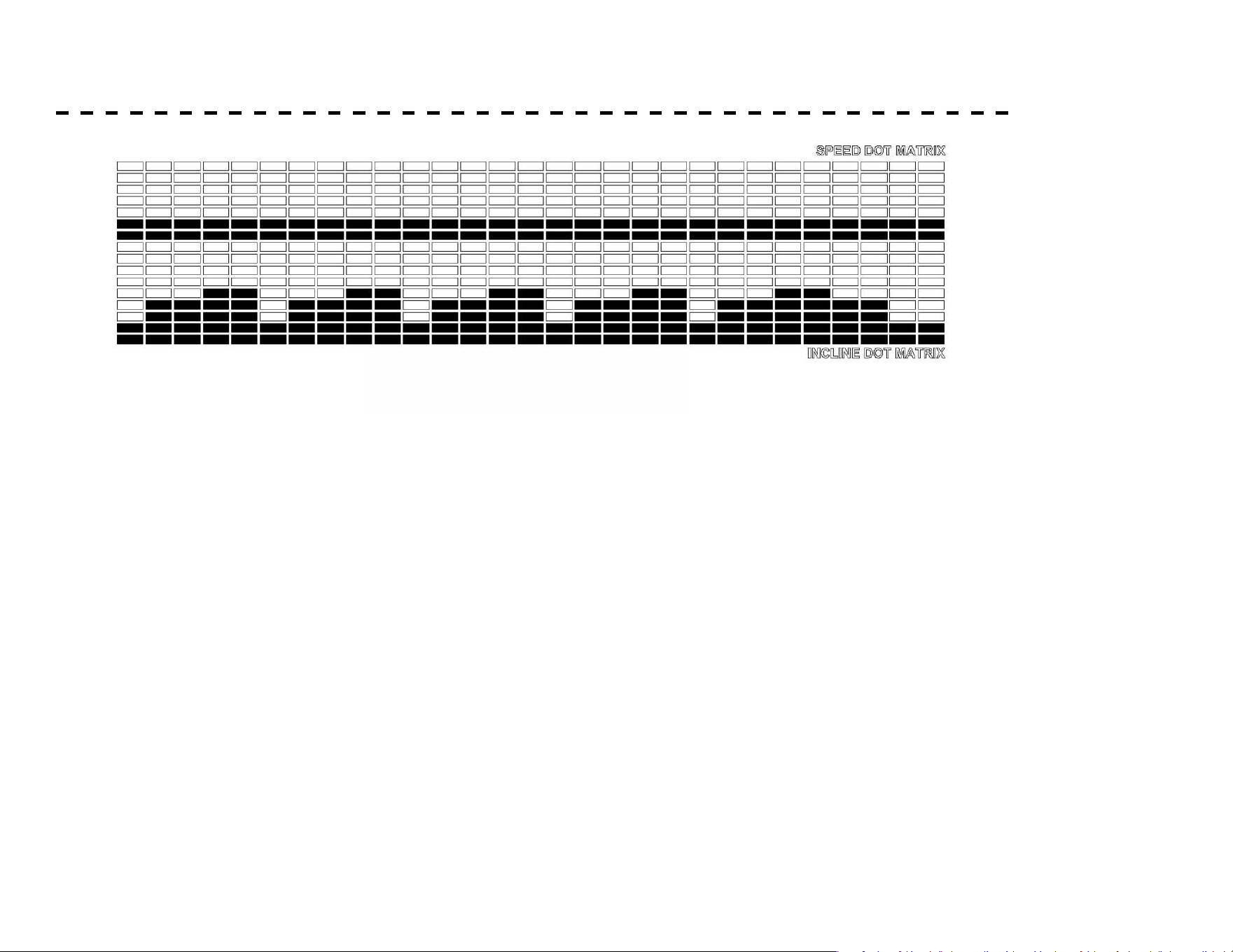
PRESET PROGRAMS
19
P9
P10
P11
P12
P 5 ~ P 8 PROGRAM PROFILE
19
P9
P10
P11
P12
P 5 ~ P 8 PROGRAM PROFILE
19
P9
P10
P11
P12
P 5 ~ P 8 PROGRAM PROFILE
6.1 - 7.5 MPH
4.1 - 6.0 MPH
2.1 - 4.0 MPH
0.5 - 2.0 MPH
6.1 - 7.5 MPH
4.1 - 6.0 MPH
2.1 - 4.0 MPH
0.5 - 2.0 MPH
6.1 - 7.5 MPH
4.1 - 6.0 MPH
2.1 - 4.0 MPH
0.5 - 2.0 MPH
6.1 - 7.5 MPH
4.1 - 6.0 MPH
2.1 - 4.0 MPH
0.5 - 2.0 MPH
6.1 - 7.5 MPH
4.1 - 6.0 MPH
2.1 - 4.0 MPH
0.5 - 2.0 MPH
6.1 - 7.5 MPH
4.1 - 6.0 MPH
2.1 - 4.0 MPH
0.5 - 2.0 MPH
34
PRESET PROGRAMS
19
P9
P10
P11
P12
P 5 ~ P 8 PROGRAM PROFILE
6.1 - 7.5 MPH
4.1 - 6.0 MPH
2.1 - 4.0 MPH
0.5 - 2.0 MPH
6.1 - 7.5 MPH
4.1 - 6.0 MPH
2.1 - 4.0 MPH
0.5 - 2.0 MPH

35
Speed P9 P10 P11 P12
Level 1 Speed Incline Speed Incline Speed Incline Speed Incline
Interval 1 2.0 mph Level 2 2.0 mph Level 2 3.0 mph Level 2 3.0 mph Level 3
Interval 2 3.0 4 4.0 3 3.0 4 4.0 6
Interval 3 3.0 4 6.0 4 6.0 6 5.0 6
Interval 4 4.0 6 2.0 5 6.0 2 6.0 8
Interval 5 4.0 6 4.0 2 6.0 4 7.0 8
Interval 6 5.0 4 6.0 3 7.5 6 7.5 3
Interval 7 5.0 4 2.0 4 7.5 2 7.0 6
Interval 8 3.0 2 4.0 5 7.5 4 6.0 6
Interval 9 3.0 2 6.0 2 3.0 6 5.0 8
Interval 10 4.0 4 2.0 3 3.0 2 6.0 8
Interval 11 4.0 4 4.0 4 6.0 4 7.0 3
Interval 12 5.0 6 6.0 5 6.0 6 7.5 6
Interval 13 5.0 6 2.0 2 6.0 2 7.0 6
Interval 14 3.0 4 4.0 3 7.5 4 6.0 8
Interval 15 3.0 4 6.0 4 7.5 6 5.0 8
Interval 16 4.0 2 2.0 5 7.5 2 6.0 3
Interval 17 4.0 2 4.0 2 3.0 4 7.0 6
Interval 18 5.0 4 6.0 3 3.0 6 7.5 6
Interval 19 5.0 4 2.0 4 6.0 2 7.0 8
Interval 20 3.0 6 4.0 5 6.0 4 6.0 8
Interval 21 3.0 6 6.0 2 6.0 6 5.0 3
Interval 22 4.0 4 2.0 3 7.5 2 6.0 6
Interval 23 4.0 4 4.0 4 7.5 4 7.0 6
Interval 24 5.0 2 6.0 5 7.5 6 7.5 8
Interval 25 5.0 2 2.0 2 3.0 2 7.0 8
Interval 26 3.0 4 4.0 3 3.0 4 6.0 6
Interval 27 3.0 4 6.0 4 6.0 6 5.0 6
Interval 28 4.0 6 2.0 5 6.0 2 6.0 3
Interval 29 4.0 6 4.0 2 6.0 4 7.0 3
PRESET PROGRAMS
LEVEL 2 Based on LEVEL 1, but increases 1 level and 2.0 MPH.
LEVEL 3 Based on LEVEL 2, but increases 1 level and 2.0 MPH.
36
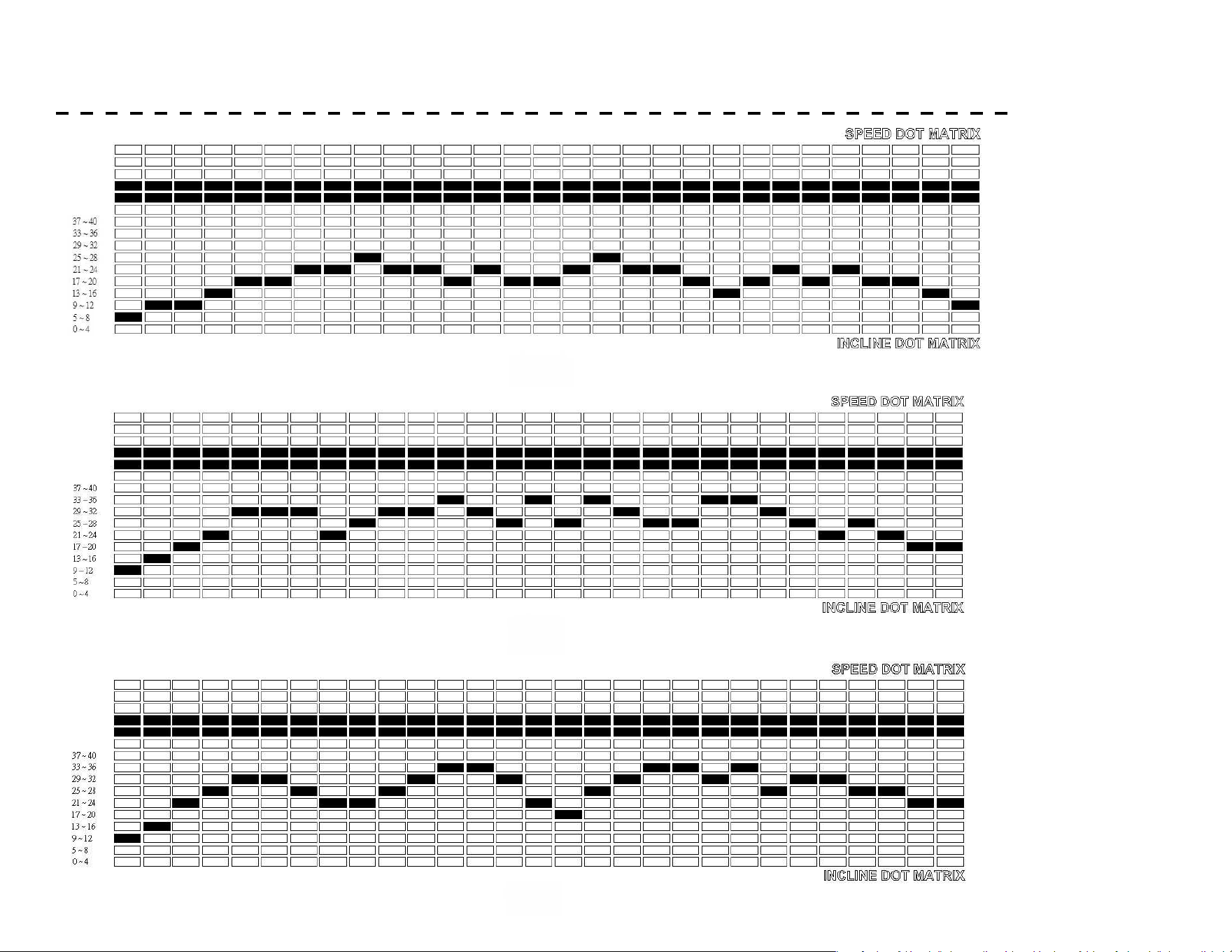
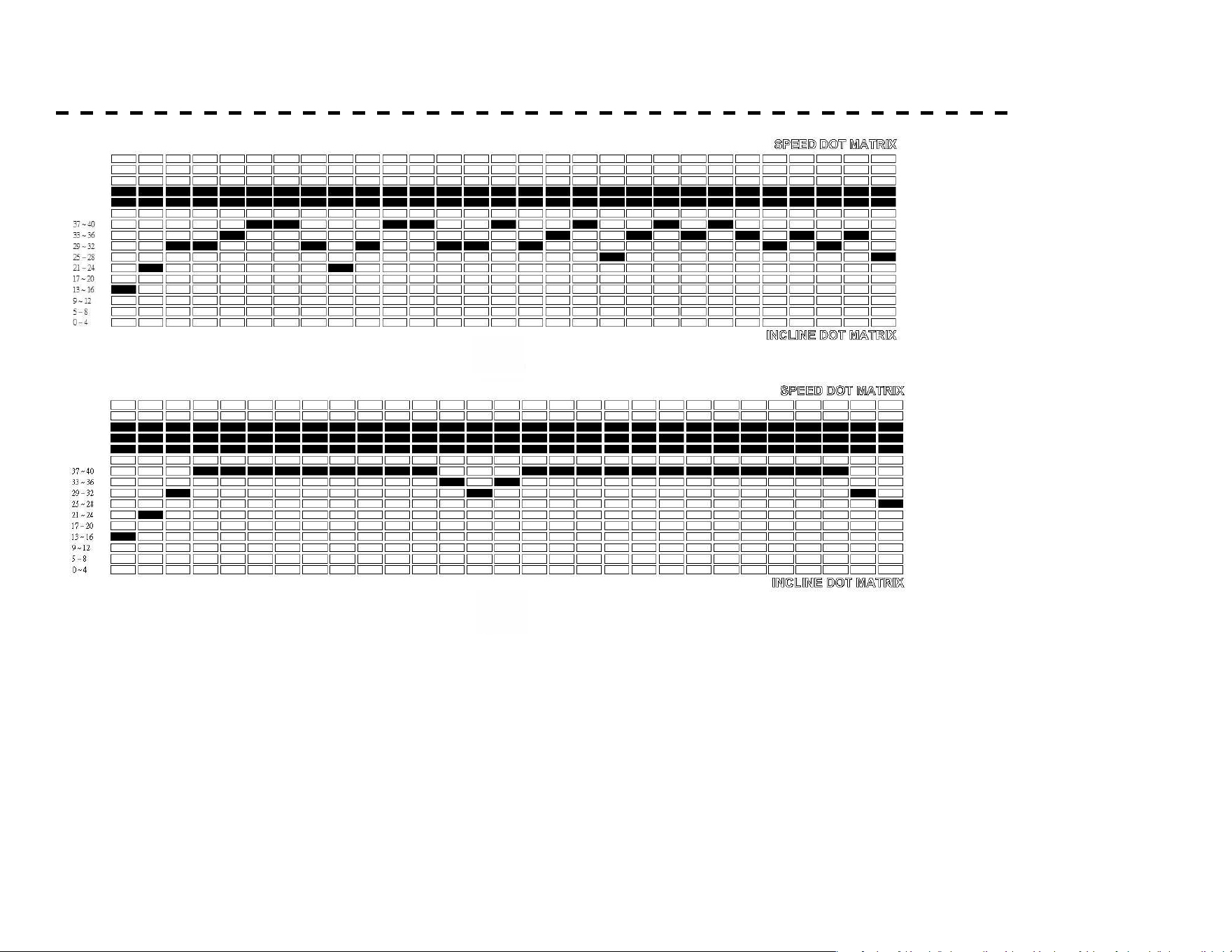
PRESET PROGRAMS - CLIMBING MODE
21
CLIMBING MODE PRESET PROGRAM PROFILE AND DATA
P2
P1
P2
P3
P4
P5
P1 ~ P5 PROGRAM PROFILE
21
CLIMBING MODE PRESET PROGRAM PROFILE AND DATA
P2
P1
P2
P3
P4
P5
P1 ~ P5 PROGRAM PROFILE
21
CLIMBING MODE PRESET PROGRAM PROFILE AND DATA
P2
P1
P2
P3
P4
P5
P1 ~ P5 PROGRAM PROFILE
36
3.1 - 3.7 MPH
2.1 - 3.0 MPH
0.5 - 2.0 MPH
3.1 - 3.7 MPH
2.1 - 3.0 MPH
0.5 - 2.0 MPH
3.1 - 3.7 MPH
2.1 - 3.0 MPH
0.5 - 2.0 MPH
37
PRESET PROGRAMS
21
CLIMBING MODE PRESET PROGRAM PROFILE AND DATA
P2
P1
P2
P3
P4
P5
P1 ~ P5 PROGRAM PROFILE
21
CLIMBING MODE PRESET PROGRAM PROFILE AND DATA
P2
P1
P2
P3
P4
P5
P1 ~ P5 PROGRAM PROFILE
3.1 - 3.7 MPH
2.1 - 3.0 MPH
0.5 - 2.0 MPH
3.1 - 3.7 MPH
2.1 - 3.0 MPH
0.5 - 2.0 MPH

38
Speed P1 P2 P3 P4 P5
Level 1 Speed Incline Speed Incline Speed Incline Speed Incline Speed Incline
Interval 1 3.0 MPH Level 8 3.0 MPH Level 10 3.0 MPH Level 12 3.0 MPH Level 15 3.7 MPH Level 15
Interval 2 3.0 10 3.0 15 3.0 14 3.0 22 3.7 23
Interval 3 3.0 11 3.0 18 3.0 23 3.0 30 3.7 30
Interval 4 3.0 15 3.0 22 3.0 27 3.0 30 3.7 40
Interval 5 3.0 18 3.0 29 3.0 30 3.0 35 3.7 40
Interval 6 3.0 20 3.0 30 3.0 31 3.0 38 3.7 40
Interval 7 3.0 22 3.0 31 3.0 28 3.0 38 3.7 40
Interval 8 3.0 23 3.0 24 3.0 23 3.0 28 3.7 40
Interval 9 3.0 25 3.0 26 3.0 24 3.0 24 3.7 40
Interval 10 3.0 24 3.0 29 3.0 26 3.0 30 3.7 40
Interval 11 3.0 23 3.0 32 3.0 30 3.0 38 3.7 40
Interval 12 3.0 20 3.0 35 3.0 34 3.0 38 3.7 40
Interval 13 3.0 21 3.0 32 3.0 35 3.0 30 3.7 35
Interval 14 3.0 17 3.0 28 3.0 32 3.0 30 3.7 30
Interval 15 3.0 19 3.0 34 3.0 22 3.0 38 3.7 35
Interval 16 3.0 23 3.0 32 3.0 20 3.0 32 3.7 40
Interval 17 3.0 25 3.0 26 3.0 25 3.0 35 3.7 40
Interval 18 3.0 24 3.0 26 3.0 29 3.0 39 3.7 40
Interval 19 3.0 23 3.0 33 3.0 35 3.0 28 3.7 40
Interval 20 3.0 20 3.0 31 3.0 35 3.0 36 3.7 40
Interval 21 3.0 16 3.0 30 3.0 32 3.0 40 3.7 40
Interval 22 3.0 18 3.0 25 3.0 33 3.0 33 3.7 40
Interval 23 3.0 21 3.0 22 3.0 28 3.0 37 3.7 40
Interval 24 3.0 18 3.0 25 3.0 29 3.0 33 3.7 40
Interval 25 3.0 21 3.0 22 3.0 29 3.0 29 3.7 40
Interval 26 3.0 18 3.0 25 3.0 27 3.0 35 3.7 40
Interval 27 3.0 17 3.0 23 3.0 26 3.0 29 3.7 40
Interval 28 3.0 13 3.0 20 3.0 24 3.0 35 3.7 30
Interval 29 3.0 10 3.0 17 3.0 22 3.0 25 3.7 25
PRESET PROGRAMS
39
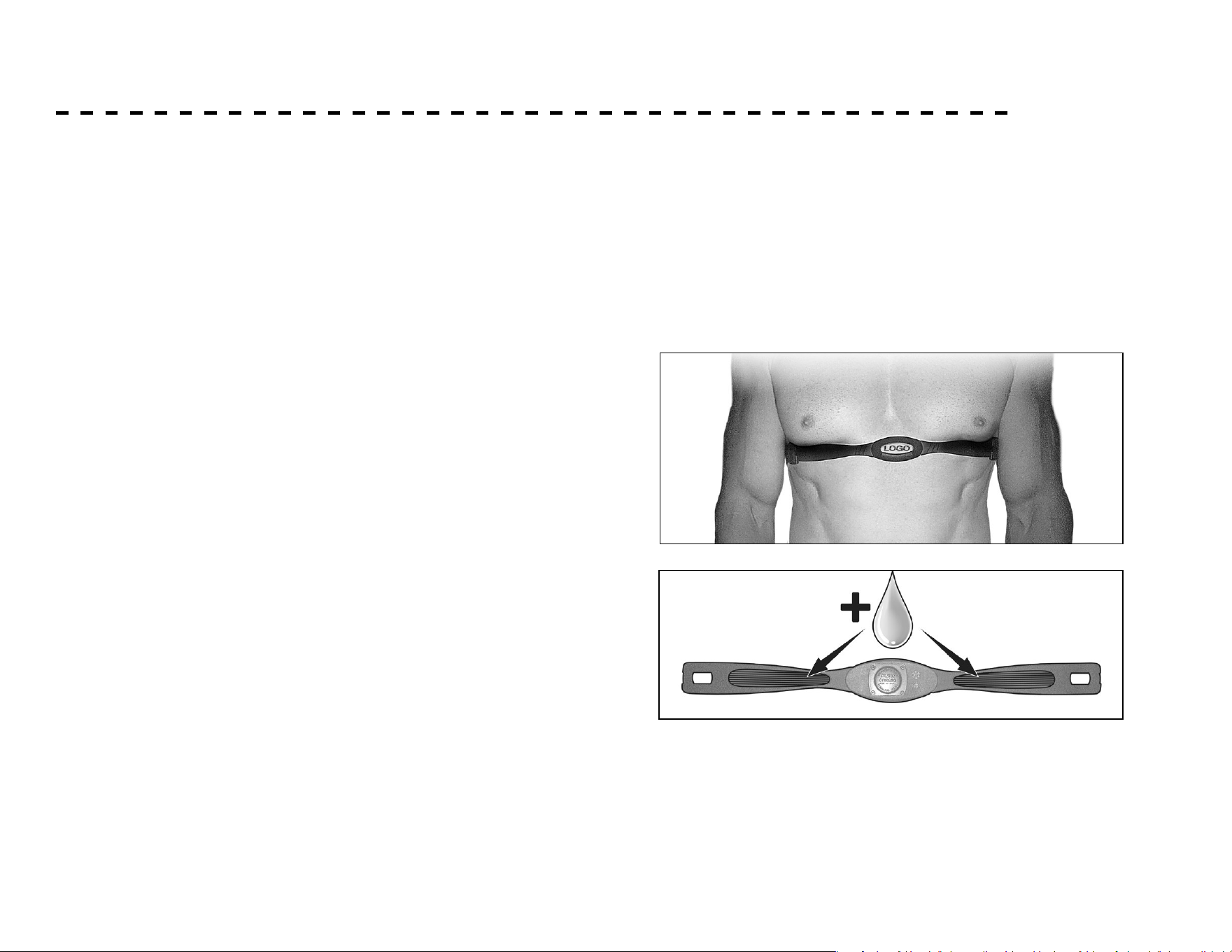
HEART RATE CHEST STRAP* (NOT INCLUDED)
1. Attach the transmitter to the elastic strap using the
interlocking key.
2. Adjust the strap as tightly as possible as long as the strap
is not too tight to remain comfortable.
3. Position the transmitter with the logo centered in
the middle of your torso facing away from your chest
(some people must position the transmitter slightly
left of center). Attach the nal end of the elastic strap
by inserting the round end and, using the locking parts,
secure the transmitter and strap around your chest.
4. Position the transmitter directly below the pectoral
muscles.
5. Sweat is the best conductor to measure very minute
heart beat electrical signals. However, plain water can
also be used to pre-wet the electrodes (2 ribbed oval
areas on the reverse side of the belt and both sides of
the transmitter). It’s also recommended that you wear
the transmitter strap a few minutes before your work
out. Some users, because of body chemistry, have a more
dicult time in achieving a strong, steady signal at the
beginning. After “warming up”, this problem lessens.
6. Your workout must be within range - distance between
transmitter/receiver – to achieve a strong steady signal.
The length of range may vary somewhat but generally
stay close enough to the console to maintain good,
strong, reliable readings. Wearing the transmitter directly
on bare skin assures you of proper operation. If you wish,
you may wear the transmitter over a shirt. To do so, wet
the areas of the shirt that the electrodes will rest upon.
Note: The transmitter is automatically activated when it detects
activity from the user’s heart. Additionally, it automatically
deactivates when it does not receive any activity. Although the
transmitter is water resistant, moisture can have the eect of
creating false signals, so you should take precautions to completely
dry the transmitter after use to prolong battery life (estimated
transmitter battery life is 2500 hours). The replacement battery is
Panasonic CR2032.
40
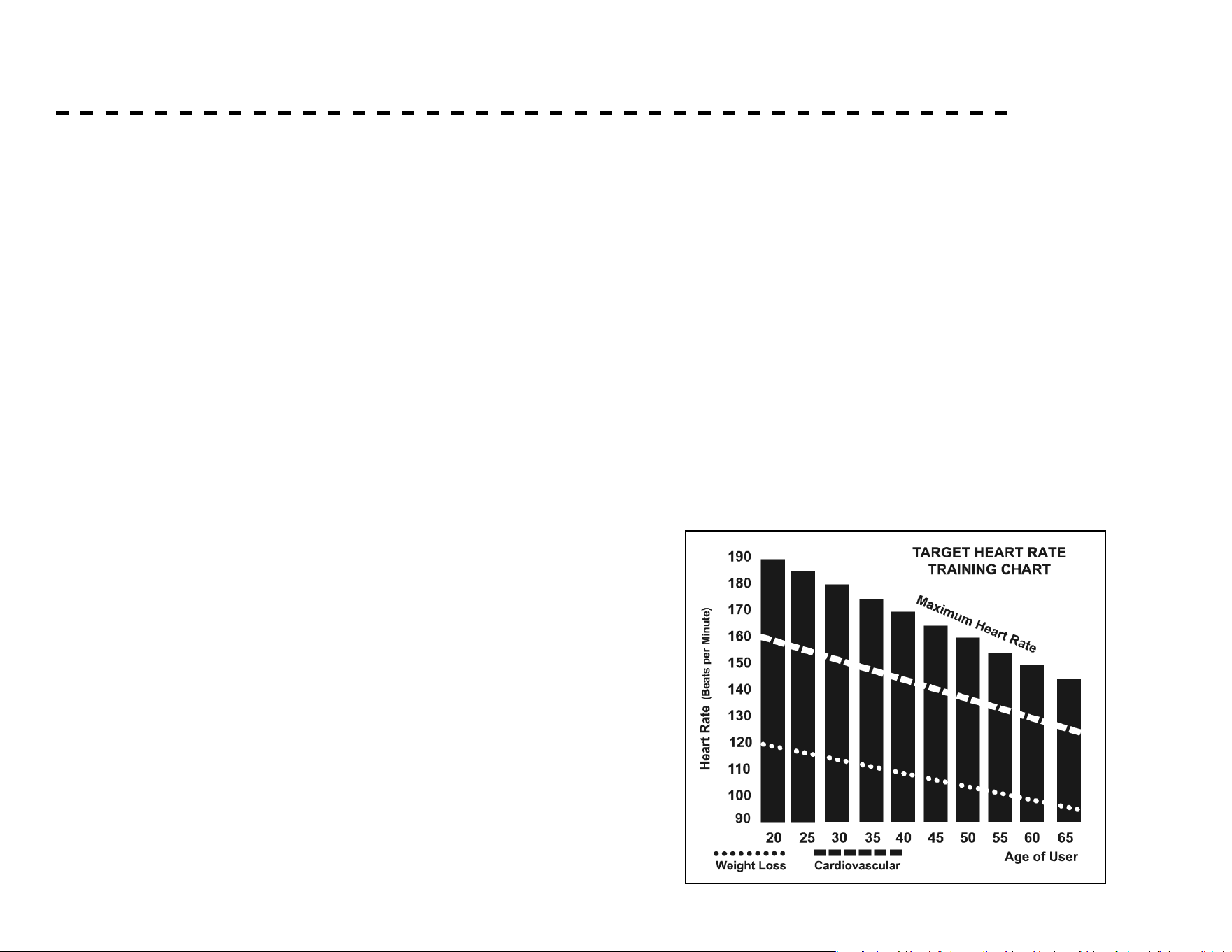
HEART RATE EXERTION
The two most popular reasons for, or goals, of exercise are cardiovascular
tness (training for the heart and lungs) and weight control. The black
columns on the chart represent the MHR for a person whose age is
listed at the bottom of each column. The training heart rate, for either
cardiovascular tness or weight loss, is represented by two dierent lines
that cut diagonally through the chart. A denition of the lines’ goal is in
the bottom left-hand corner of the chart. If your goal is cardiovascular
tness or if it is weight loss, it can be achieved by training at 80% or 60%,
respectively, of your MHR on a schedule approved by your physician.
Consult your physician before participating in any exercise program.
With this Spirit Fitness unit you may use the heart rate monitor feature
without using the Heart Rate program. However, when using the heart
rate monitor feature in conjunction with the Heart Rate programs, the
machine will automatically adjust speed or incline to maintain the desired
heart rate.
The old motto, “no pain, no gain”, is a myth that has been
overpowered by the benets of exercising comfortably. A great deal
of this success has been promoted by the use of heart rate monitors.
With the proper use of a heart rate monitor, many people nd that
their usual choice of exercise intensity was either too high or too low
and exercise is much more enjoyable by maintaining their heart rate in
the desired benet range.
To determine the benet range in which you wish to train, you must
rst determine your Maximum Heart Rate. This can be accomplished
by using the following formula: 220 minus your age. This will give
you the Maximum Heart Rate (MHR)for someone of your age. To
determine the eective heart rate range for specic goals you simply
calculate a percentage of your MHR. Your Heart rate training zone
is 50% to 90% of your maximum heart rate. 60% of your MHR is
the recommended for burning fat while 80% is recommended for
strengthening the cardio vascular system. This 60% to 80% is the
zone to stay in for maximum benet.
For someone who is 40 years old their
target heart rate zone is calculated:
220 – 40 = 180 (maximum heart rate)
180 x .6 = 108 beats per minute (60% of maximum)
180 X .8 = 144 beats per minute (80% of maximum)
So for a 40 year old the training zone would
be 108 to 144 beats per minute.
If you enter your age during programming the console will perform
this calculation automatically. Entering your age is used for the Heart
Rate programs. After calculating your MHR you can decide upon
which goal you would like to pursue.

41
HEART RATE - PERCEIVED EXERTION
Heart rate is important but listening to your body also has a lot
of advantages. There are more variables involved in how hard
you should workout than just heart rate. Your stress level, phys-
ical health, emotional health, temperature, humidity, the time of
day, the last time you ate and what you ate all contribute to the
intensity at which you should workout. If you listen to your body
it will tell you all of these things.
The rate of perceived exertion (RPE), also known as the Borg
scale, was developed by Swedish physiologist G.A.V. Borg.
This scale rates exercise intensity from 6 to 20 depending upon
how you feel or the perception of your eort.
The scale is as follows:
Rating Perception of Eort
You can get an approximate heart rate level for each rating by
simply adding a zero to each rating. For example a rating of 12 will
result in an approximate heart rate of 120 beats per minute. Your
RPE will vary depending on the factors discussed earlier. If your
body is strong and rested, you will feel strong and your pace will
feel comfortable. When your body is in this condition, you are able
to train harder and the RPE will support this. If you are feeling tired
and sluggish, it is because your body needs a break. In this
condition, your pace will feel dicult. Again, this will show up in
your RPE and you will train at the proper level for that day.
6 Minimal
7 Very, Very Light
8 Very, Very Light +
9 Very Light
10 Very Light +
11 Fairly Light
12 Comfortable
13 Somewhat Hard
14 Somewhat Hard +
15 Hard
16 Hard +
17 Very Hard
18 Very Hard +
19 Very, Very Hard
20 Maximal

42
1. Use a slightly damp cloth to clean areas where sweat or
oil made contact with the machine.
2. Use a microber cloth to clean the display and remove
unwanted oils and other things that may damage the
screen.
3. Avoid leaving paper or other small debris in the
cupholders.
MAINTENANCE & CARE
General Cleaning
Post-Workout Machine Care
Dirt, dust, and hair can block air inlets and accumulate on
the running belt. Please vacuum underneath your unit on a
monthly basis to prevent excess build-up of dirt that can
get sucked up and get into the inner workings under the
motor cover. Every other month, you should remove the
motor cover and carefully vacuum out dirt and hair that may
accumulate.
UNPLUG THE POWER CORD BEFORE THIS TASK.
Sanitizing Your XTERRA Fitness Equipment
• Unupholstered high-contact surfaces (hard plastics) can be
sanitized using a 75% isopropyl alcohol solution and a clean, dry
cloth.Spray surfaces to be sanitized, and use the dry cloth to
wipe clean. Allow surfaces to dry before using.
• For upholstered or soft-plastic surfaces, use a conditioner
after sanitizing.Be sure to follow the instructions provided
by the conditioner manufacturer to ensure proper use of the
conditioner.
• Alternatively, you can make your own spray by mixing the
proper ratio of isopropyl alcohol and distilled water to reach a
75% solution.
!
43
MAINTENANCE & CARE - CONTINUED
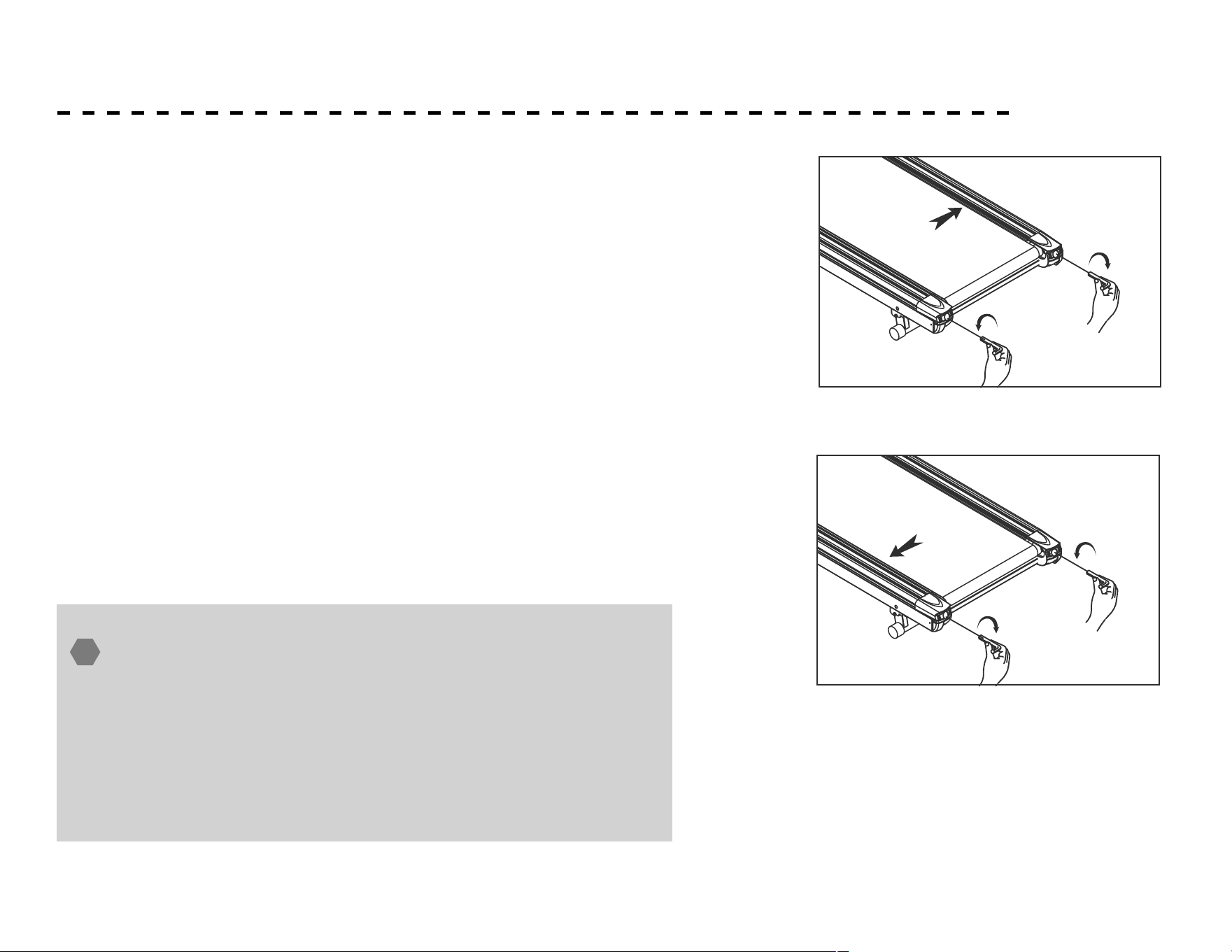
Aligning the Running Belt
Ensure the running belt is centered on your treadmill at all times . Running
style and Non-level surface are two instances which may cause the belt to
drift o center .
Minor adjustments to the two bolts at the rear of the treadmill are
necessary when the belt has drifted o center . See g . A & B .
1. Press the Power Switch (located at the front of the treadmill) to ON
position and ensure Safety Key is properly placed onto the computer
console, press the START button to begin running, then increase the
treadmill’s speed to 2 MPH .
2. Stand right behind the treadmill and to determine which side the belt
is drifting .
3. If the belt drifts to the right, turn the right adjustment bolt one-
quarter of a turn clockwise and the left adjustment bolt one-quarter
counter clockwise (See Fig . A) .
4. If the belt drifts to the left, turn the left adjustment bolt one-quarter
of a turn clockwise and turn the right adjustment bolt one-quarter
turn counter-clockwise (See Fig . B) .
5. Observe the tracking of the belt for about two minutes . Repeat Steps
3, 4, and 5 as needed .
DO NOT OVERTIGHTEN – Over tightening will cause belt
damage and premature bearing failure. If you tighten the belt
a lot and it still slips, the problem could actually be the drive
belt - located under the motor cover - that connects the
motor to the front roller. If that belt is loose it feels similar
to the walking belt being loose. Tightening the motor belt
should be done by a trained service person.
!
drifts to the left
FIGURE B
drifts to the right
FIGURE A
ALIGNING THE RUNNING BELT
Ensure the running belt is centered on your treadmill at all times .
Running style and Non-level surface are two instances which may
cause the belt to drift off center .
Minor adjustments to the two bolts at the rear of the treadmill are
necessary when the belt has drifted off center . See fig . A & B .
1 . Press the Master Power Switch (located at the front of the treadmill)
to ON position and ensure Safety Key is properly placed onto the
computer console, press the START button to begin running, then
increase the treadmill's speed to 3 kph .
2 . Stand right behind the treadmill and to determine which side the belt
is drifting .
3 . If the belt drifts to the right, turn the right adjustment bolt
one-quarter of a turn clockwise and the left adjustment bolt
one-quarter counter clockwise (See Fig . A) .
4 . If the belt drifts to the left, turn the left adjustment bolt
one-quarter of a turn clockwise and turn the right adjustment bolt one-quarter
turn counter-clockwise (See Fig . B) .
5 . Observe the tracking of the belt for about two minutes . Repeat Steps 3, 4, and 5 as needed .
ADJUSTING THE RUNNING BELT TENSION
Adjust the belt tension if it begins to slip on the rollers . This is important as it increased the longevity of
the treadmills components .
Before adjusting belt tension, keep the belt loose
1 . Turn the MASTER POWER SWITCH to the ON position and make sure safety key is pressed in.
2 . Press START button to start running the belt, then increase speed to 3KPH .
3 . Turn both adjustment screws an equal amount, approximately one-quarter turn clockwise .
4 . Slow the belt by holding onto the handrails and applying more weights as you walk, (as if you are
walking downhill) . Then stepping heavily on the belt to see if the belt slips .
5 . If the belt slips, adjust one-quarter turn clockwise and repeat STEP 4 if necessary .
ALWAYS BE CAREFUL NOT TO OVERTIGHTEN THE RUNNING BELT.
CLEANING AND INSPECTING THE RUNNING BELT
Turn off power and unplug from electrical outlet .
Carefully position the treadmill on its side .
Use a damp cloth to wipe off the inside of the running belt . Carefully rotate the running belt by hand to
clean the entire inside face . Return treadmill to its upright position.
If running belt edges are frayed, check the running belt adjustment .
If seams are splitting, call your retailer or nearest authorized service center .
24

44
MAINTENANCE & CARE - CONTINUED
Aligning the Running Belt Tension
Adjust the belt tension if it begins to slip on the rollers . This
is important as it increased the longevity of the treadmills
components .
Before adjusting belt tension, keep the belt loose
1. Turn the MASTER POWER SWITCH to the ON position and
make sure safety key is pressed in.
2. Press START button to start running the belt, then increase
speed to 2 MPH .
3. Turn both adjustment screws an equal amount,
approximately one-quarter turn clockwise .
4. Slow the belt by holding onto the handrails and applying
more weights as you walk, (as if you are walking downhill) .
Then stepping heavily on the belt to see if the belt slips .
5. If the belt slips, adjust one-quarter turn clockwise and
repeat STEP 4 if necessary .
ALWAYS BE CAREFUL NOT TO OVERTIGHTEN THE
RUNNING BELT.

45
MAINTENANCE & CARE - CONTINUED
Item Daily (Before Use) Daily (After Use) Weekly Monthly 3 Months 6 Months
Entire Machine
Examine if the frame is
stable for exercise.
Adjust balancer to make
it stably positioned on the
ground.
Use dry cloth to wipe and
clear sweat and dust on the
surface of machine.
Use damp cloth to clean. (Do
not use Solubility Cleaners.)
Use water for plastic parts. Use
silicone oil or wax for metal
parts.
Location
Assure enough safe space
around the machine, and
make sure no dangerous
objects around.
Use wet cloth to clean the
ground.
Do not put wax on
the ground.
Vacuum dust at
the bottom and around
the machine.
Power Cable
Assure power cable
is well-plugged and not
pressed by the machine.
Turn o the power
or unplug power cable.
Running Belt
Assure no objects on the
belt, and run the machine
at 2-3 MPH to see if the belt
drifts.
Use dry cloth to wipe and
clear the surface of running
belt.
Use damp cloth to clean (Do not
use Solubility Cleaners).
Running Belt Tension
Adjustment
Check if running belt is
slipping.
Lubrication of Running Belt
Use a silicone lubricant to
lubricate whenever reaching
112 miles.
Side Panel
Check if they are well-xed and
make sure no breakdown on the
panel.
Bolt
Check if all bolts are rmly
fastened and no rusting.
The Inside of Motor Cover
Open motor cover and
vacuum all dust.
Safety Key
Turn the power on and
remove safety key to check
if it is in normal function.
Make sure safety key is re-
placed on the console.

46
DECK LUBRICATION
To lubricate your Hiker Treadmill belt:
1. Turn the power switch o and unplug the power cord from the
wall outlet.
2. Measure 18” from the edge of the motor cover; kneel down and
reach under the belt approximately 4-6” from one edge. Squirt
a line of lubricant about 1/8” wide x 15” long in an “S” pattern
perpendicular to the motor cover.
3. Repeat the process on the opposite side.
4. Plug the electrical cord back into the outlet and turn the power
switch on.
5. Walk on the belt at a moderate speed for ve minutes to evenly
distribute the silicone lube.
To ensure the longevity and proper function of your Hiker
Treadmill, proper belt maintenance is required. You should
regularly check between the Hiker Treadmill belt and the
top of the Hiker Treadmill base for proper lubrication,
and to ensure that no dirt or debris has become trapped.
Keeping the deck clean and lubricated at the recommended
intervals ensures the longest life possible for your unit.
Should lubrication dry out, or dirt become trapped, the
friction between the belt and deck increases. Increased
friction places undue stress on the drive motor, drive
belt, and electronic motor control board which could
result in catastrophic failure of these essential, expensive
components.
Failure to clean and lubricate the deck at regular intervals
may void the warranty.
As a part of your routine maintenance schedule, belt
lubrication and cleaning should be performed every 90 days,
after 90 hours of use, or earlier if you notice that the deck
is dry or dirty. Please also be sure to check belt lubrication
before rst use.
Regularly check belt lubrication by completing the following
steps:
1. Ensure that your machine is o, and that the power cord is
unplugged to minimize risk of injury.
2. Reach between the running belt and the top of the Hiker
Treadmill base to verify that lubrication is present.
1. The word of 'LUBE' will ash in every 3 seconds on the
console once accumulated running distance reaches 112
MPH to remind user to do the maintenance.
2. Press any button to jump out of the alert mode. Word of
'LUBE will show up again whenever the machine re-starts
if the user doesn't eliminate the word by taking action of
No. 3 as below.
3. Press " STOP & "SPEED Slow (-)" buttons at the same
time to remove the word of 'LUBE', but distance will keep
accumulating.
Do not lubricate with anything other than XTERRA Fitness
approved lubricant. Your Hiker Treadmill comes with one tube of
Hiker Treadmill belt lubricant.
Extra tubes can be ordered directly from: www.Xterratness.com,
or by calling our customer service department at (800)258-8511.

47
BELT AND DECK CLEANING
To clean your Hiker Treadmill belt:
1. Ensure that your machine is o, and that the power cord
is unplugged to minimize risk of injury.
2. Grab one edge of the Hiker Treadmill belt, and lift
slightly to expose the area between the top of the Hiker
Treadmill base and the running belt.
3. Do a visual check for any dirt or debris accumulation.
4. Should dirt and debris be present, slide a towel or
cleaning cloth between the Hiker Treadmill belt and top
of the Hiker Treadmill base until you can grasp one end on
each side. (The cleaning cloth should be longer than the
running belt is wide to achieve this.)
5. Using both hands, drag the cleaning cloth up and down
the length of the Hiker Treadmill base 1-2 times.
6. For excessive dirt accumulation, rotate the belt halfway,
and repeat step 5. Continue until your cleaning cloth is no
longer picking up any dirt.
7. Remove cleaning cloth from Hiker Treadmill before
plugging back in.
Belt & Deck Cleaning
48
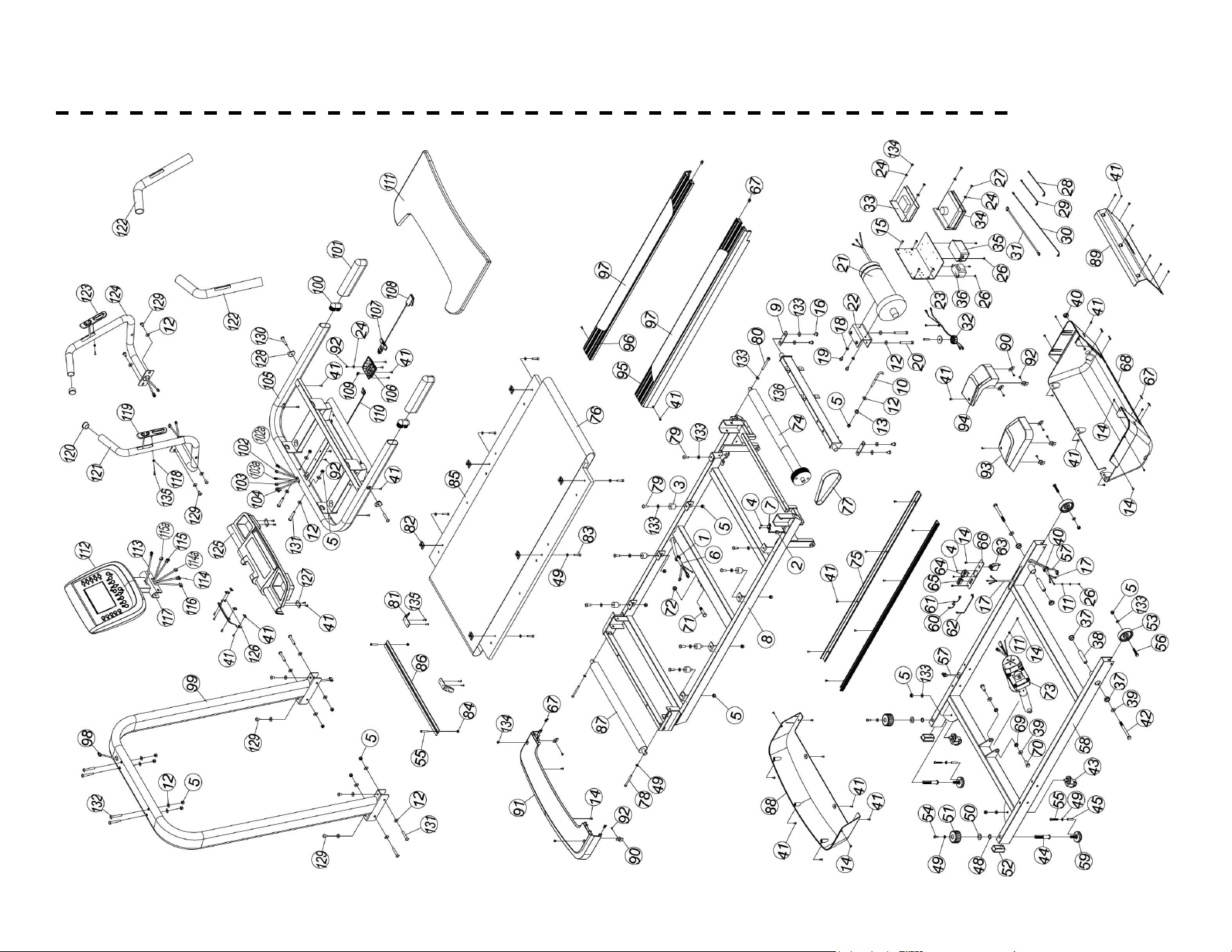
EXPLODED VIEW DIAGRAM
EXPLODED DRAWING
26

49
WARRANTY - RESIDENTIAL
Eective January 03, 2024- TR95H Hiker Treadmill LIMITED WARRANTY
Home Use Limited Warranty
XTERRA Fitness Inc. warrants all its home use Hiker Treadmill parts for a period of time listed below, from the date of retail sale, as de-
termined by a sales receipt or in the absence of a sales receipt, eighteen (18) months from the original factory shipping date. XTERRA
Fitness’s responsibilities include providing new or remanufactured parts, at XTERRA Fitness’s option, and technical support to our in-
dependent dealers and servicing organizations. In the absence of a dealer or service organization, these warranties will be administered
by XTERRA Fitness directly to a consumer. The warranty period applies to the following components:
Warranty
Residential
Frame
Lifetime
Parts
2 Years
Labor
1 Year
RESPONSIBILITIES OF THE CONSUMER
This warranty applies only to products in ordinary household use, and the consumer/facility is responsible for the items listed below:
1. Proper use of the Hiker Treadmill in accordance with the instructions provided in this manual
2. Proper installation in accordance with instructions provided with the Hiker Treadmill and with all local electric codes.
3. Expenses for making the Hiker Treadmill accessible for servicing, including any item that was not part of the Hiker Treadmill at the
time it was shipped from the factory.
4. Damages to the Hiker Treadmill nish during shipping, installation or following installation.
5. Routine maintenance of this unit as specied in this manual.

50
WARRANTY - CONTINUED
What is not covered?
EXCLUSIONS
This warranty does not cover the following:
1. CONSEQUENTIAL, COLLATERAL, OR INCIDENTAL DAMAGES SUCH AS PROPERTY DAMAGE AND INCIDENTAL EXPENSES
RESULTING FROM ANY BREACH OF THIS WRITTEN OR ANY IMPLIED WARRANTY.
Note: Some states do not allow the exclusion or limitation of incidental or consequential damages, so this limitation or exclusion
may not apply to you.
2. Service call reimbursement to the consumer. Service call reimbursement to the dealer that does not involve malfunction or defects
in workmanship or material, for units that are beyond the warranty period, for units that are beyond the service call reimbursement
period, for Hiker Treadmill not requiring component replacement, or Hiker Treadmill not in ordinary household or light commercial
use.
3. Damages caused by services performed by persons other than authorized XTERRA Fitness service companies; use of parts other
than original XTERRA Fitness parts; or external causes such as corrosion, discoloration of paint or plastic, alterations, modica-
tions, abuse, misuse, accident, improper maintenance, inadequate power supply, or acts of God.
4. Products with original serial numbers that have been removed or altered.
5. Products that have been: sold, transferred, bartered, or given to a third party.
6. XTERRA Fitness reserves the right to request proof of purchase if no warranty record exists for the product.
7. THIS WARRANTY IS EXPRESSLY IN LIEU OF ALL OTHER WARRANTIES EXPRESSED OR IMPLIED, INCLUDING THE WARRAN-
TIES OF MERCHANTABILITY AND/OR FITNESS FOR A PARTICULAR PURPOSE.
8. Product use in any environment other than a residential setting or non-dues paying facility with 5 hours use or less per day.
9. Warranties outside of the United States may vary. Please contact your local dealer for details.
Product features or specications as described or illustrated are subject to change without notice. All warranties are made by XTERRA Fitness, Inc. This warranty
applies only in the 48 contiguous United States. NOTE: This does not include Alaska or Hawaii.

51
Responsibilities of the Owner
SERVICE
Keep your bill of sale. Twelve (12) months from the date on the bill of sale or eighteen (18) months from the date of factory shipping as
determined by the serial number establishes the labor warranty period should service be required. If service is performed, it is in your
best interest to obtain and keep all receipts. This written warranty gives you specic legal rights. You may also have other rights that
vary from state to state. Service under this warranty must be obtained by following these steps, in order:
1. Contact your selling authorized XTERRA Fitness dealer. OR
2. Contact your local authorized XTERRA Fitness service organization.
3. If there is a question as to where to obtain service, contact our service department at (870) 935-1107.
4. XTERRA Fitness’ obligation under this warranty is limited to repairing or replacing, at XTERRA Fitness’ option, the product through
one of our authorized service centers. All repairs must be preauthorized by XTERRA Fitness. If the product is shipped to a service
center freight charges to and from the service center will be the customer’s responsibility. For replacement parts shipped while the
product is under warranty, the customer will be responsible for shipping and handling charges. For in-home service, the customer
will be responsible for a trip charge. There will be an additional trip charge if the customer is located over 100 miles from the
nearest service center.
5. The owner is responsible for adequate packaging upon return to XTERRA Fitness. XTERRA Fitness is not responsible for damages
in shipping. Make all freight damage claims with the appropriate freight carrier. DO NOT SHIP ANY UNIT TO OUR FACTORY
WITHOUT A RETURN AUTHORIZATION NUMBER. All units arriving without a return authorization number will be refused.
For any further information, or to contact our service department by mail, send your correspondence to:
XTERRA Fitness, Inc.
P.O. Box 2037
Jonesboro, AR 72402-2037
Product features or specications as described or illustrated are subject to change without notice. All warranties are made by XTERRA
Fitness, Inc. This warranty applies only in the 48 contiguous United States. NOTE: This does not apply to Alaska or Hawaii.
WARRANTY - CONTINUED

52
TROUBLESHOOTING
• E1 (Error 1): When the machine starts but computer could not read the signal from sensor for 7 seconds, E1 will be shown on
the computer.
• E6 (Error 6): When the machine starts but computer could not read the VR signal from incline motor for 6 seconds, E6 will be
shown on the computer. If any above trouble happens, please consult the distributor.
• E3 (Error 3): E3 shows when the cable from computer and control box is not well-connected or damaged. If the cable works
well, check if the computer or control box is damaged.
• SMELL: If any smell comes out from motor, please rstly spray out some silicone on the running board (Please refer to
RUNNING BOARD MAINTENANCE), and see if the situation improves. Then consult the distributor for necessary help.

53
www.xterrafitness.com
©2023 All Rights Reserved. TR95H Owner’s Manual
3000 Nestle Road Jonesboro, AR 72401 | Phone: 800-258-8511 | Fax: 870-935-7611