Loading ...
Loading ...
Loading ...
7
Important: All wires should be joined together using wire nuts,
solder, and/or vinyl tape. In wet environments like a valve box it is
recommended to use Orbit Grease Caps to prevent corrosion of the
connection and for protection from water infiltration.
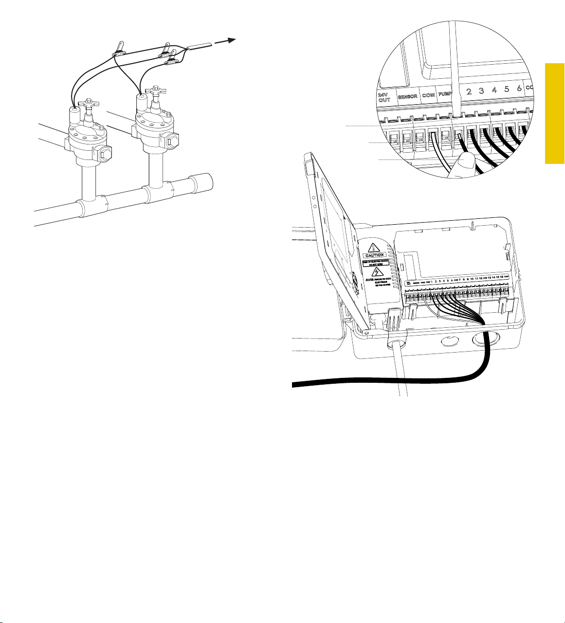
Wiring Electric Valves
Strip 1/2” (12 mm) of plastic insulation off the end of each individual
wire. Each valve has two wires. One wire (it doesn’t matter which
one) is to be connected as the common. The other valve wire is
to be connected to the specific station wire that will control that
valve. The common wires for all the valves can be connected
together to one common wire going to the controller. To avoid
electrical hazards, only one valve should be connected to each
station.
Important: The wire can be buried in the ground; however, for
more protection wires can be pulled through PVC pipe and buried
underground. Be careful to avoid burying the wires in locations
where they could be damaged by digging or trenching in the future.
Your timer is equipped with angled terminals for easy wire insertion.
Push common wire into the common terminal and, using the
included screwdriver, tighten the screw in the wire terminal to
secure the wire. Insert and tighten remaining wires to corresponding
terminal locations.
Station 1
Strip wire
Push in
Only connect one valve to
each terminal (station).
To
Timer
Wire Nut
Solenoid
Common
Wire
Valve
4. Connect Electrical Power
Indoor Locations – Insert the power cord into an 110V electrical
outlet.
Outdoor Locations – Insert the power cord into a 110 volt Ground
Fault Interrupter (GFI) outlet.
ENGLISH
Loading ...
Loading ...
Loading ...