
1
IMPORTANT SAFETY INFORMATION
We thank you for choosing our product. To ensure your safety and health, please use this
equipment correctly. It is important to read this entire manual before assembling and using the
equipment. Safe and effective use can only be achieved if the equipment is assembled,
maintained, and used properly. It is your responsibility to ensure that all users of the equipment
are informed of all warnings and precautions.
1. Before starting any exercise program, you should consult your physician to determine if you
have any medical or physical conditions that could put your health and safety at risk, or prevent
you from using the equipment properly. Your physician’s advice is essential if you are taking
medication that affects your heart rate, blood pressure or cholesterol level.
2. Be aware of your body’s signals. Incorrect or excessive exercise can damage your health. Stop
exercising if you experience any of the following symptoms: pain, tightness in your chest,
irregular heartbeat, shortness of breath, lightheadedness, dizziness, or feelings of nausea. If
you do experience any of these conditions, you should consult your physician before continuing
with your exercise program.
3. Keep children and pets away from the equipment. The equipment is designed for adult use
only.
4. Use the equipment on a solid, flat level surface with a protective cover for your floor or carpet.
To ensure safety, the equipment should have at least 2 feet (60 cm) of free space all around it.
5. Ensure that all nuts and bolts are securely tightened before using the equipment. The safety of
the equipment can only be maintained if it is regularly examined for damage and/or wear and
tear.
6. Always use the equipment as indicated. If you find any defective components while assembling
or checking the equipment, or if you hear any unusual noises coming from the equipment
during exercise, discontinue use of the equipment immediately and do not use until the problem
has been rectified.
7. Wear suitable clothing while using the equipment. Avoid wearing loose clothing that may
become entangled in the equipment.
8. Do not place fingers or objects into the moving parts of the equipment.
9. The maximum weight capacity of this unit is 220 lbs (100 kgs).
10. The equipment is not suitable for therapeutic use.
11. To avoid bodily injury and/or damage to the product or property, proper lifting and moving is
required.
12. Your product is intended for use in cool, dry conditions. You should avoid storing in extreme
cold, hot, or damp areas as this may lead to corrosion and other related problems.
13. This equipment is designed for indoor and home use only. It is not intended for commercial use!
2
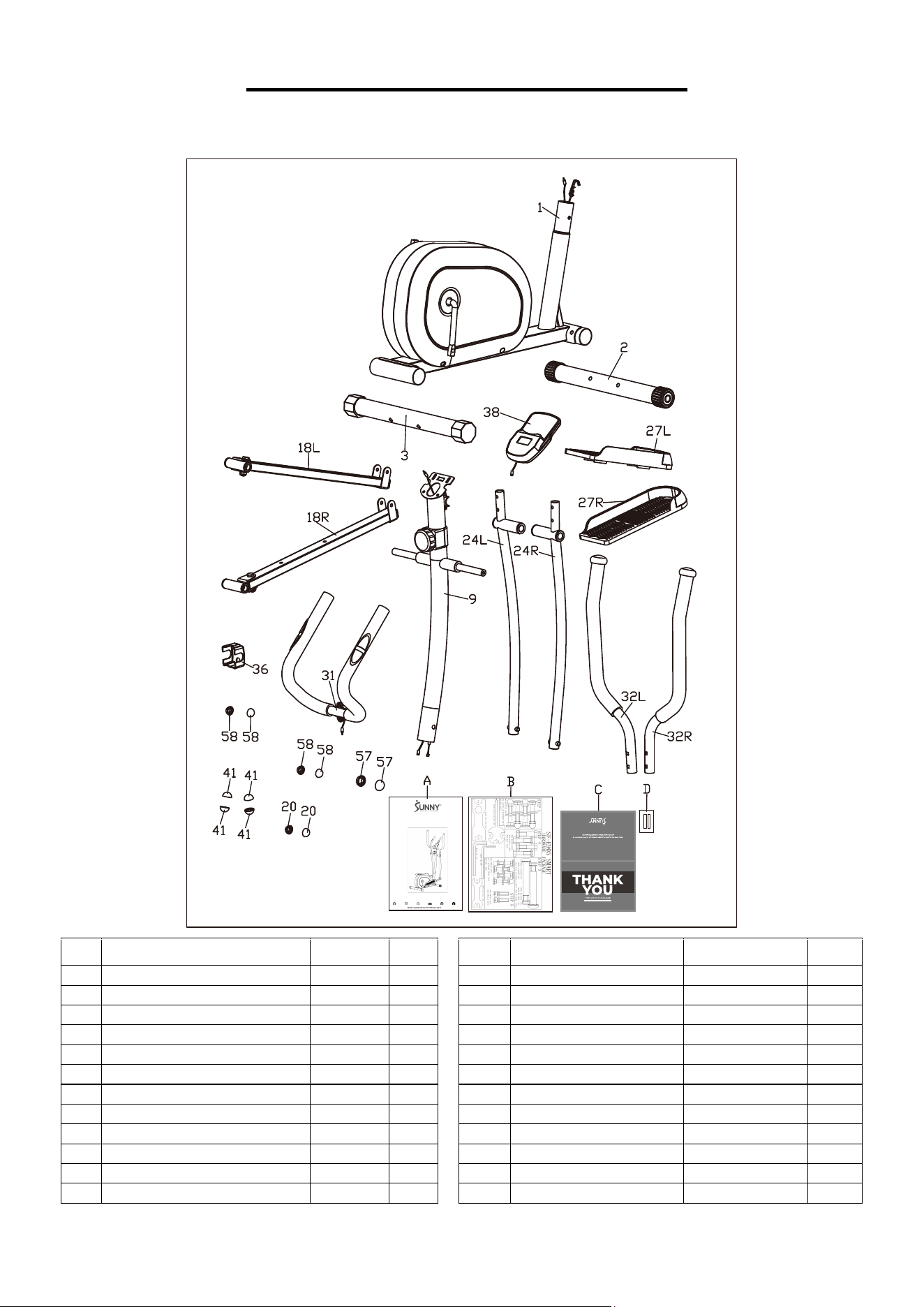
PRE-ASSEMBLY CHECK LIST
Before you start to assemble, please make sure all parts are included.
No.
Description
Spec.
Qty.
No.
Description
Spec.
Qty.
1
Main Frame
1
32L
Left Handlebar
1
2
Front Stabilizer
1
32R
Right Handlebar
1
3
Rear Stabilizer
1
36
Decorative Cover
1
9
Handlebar Post
1
38
Meter
BJHT060
1
18L
Left Pedal Support Tube
1
41
Nut Cap
S17
4
18R
Right Pedal Support Tube
1
57
Nut Cap
S19
2
20
Nut Cap
S13
2
58
Nut Cap
S14
4
24L
Left Swing Bar
1
A
Manual
1
24R
Right Swing Bar
1
B
Hardware Package
1
27L
Left Pedal
1
C
Thank You Card
1
27R
Right Pedal
1
D
Battery
AAA
2
31
Armrest
1
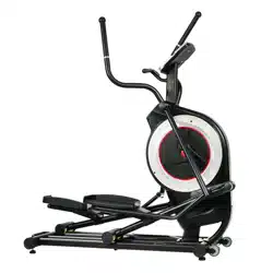
SMART MAGNETIC ELLIPTICAL
SF-E905 SMART
USER MANUAL
IMPORTANT! Please retain owner’s manual for maintenance and adjustment instructions.
Your satisfaction is very important to us, PLEASE DO NOT RETURN UNTIL YOU HAVE
CONTACTED US: [email protected]
or 1-877-90SUNNY (877-907-8669).
3
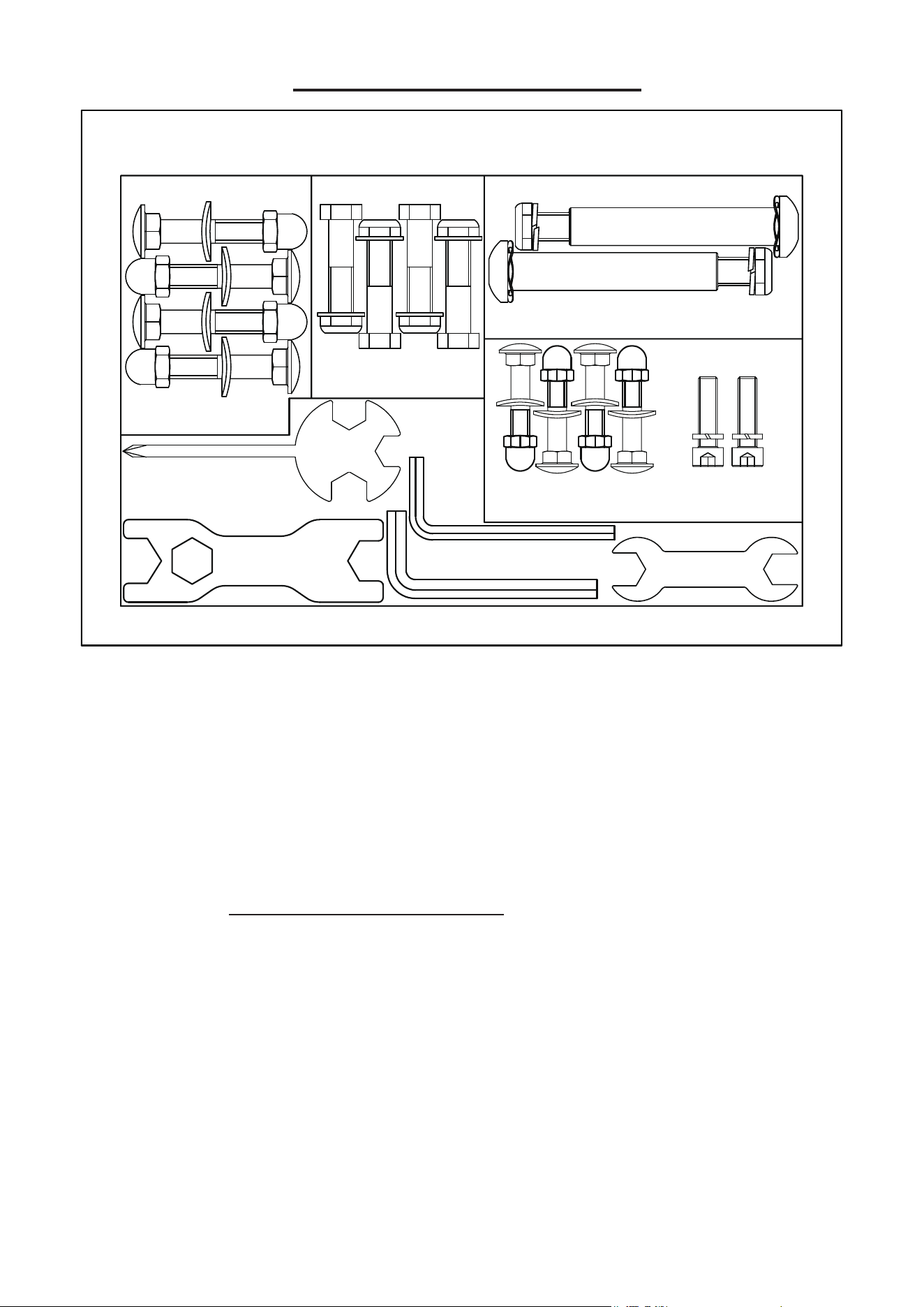
HARDWARE PACKAGE
Ordering Replacement Parts (U.S. and Canadian Customers only)
Please provide the following information in order for us to accurately identify the part(s) needed:
The model number (found on cover of manual)
The product name (found on cover of manual)
The part number found on the “EXPLODED DIAGRAM” (page 13) and “PARTS LIST” (pages
14~15)
Please contact us at support@sunnyhealthfitness.com or 1-877-90SUNNY (877-907-8669).
HARDWARE PACKAGE
STEP 1
#37 M8X40 4PCS
#14 φ20XD8.5XR25 4PCS
#33 M8 4PCS
#28 M10X45 4PCS
#54 D10X1.5 4PCS
#56 M10 4PCS
#6 M10XL57 4PCS
#7 φ10X1.5Xφ25XR28 4PCS
#8 M10 4PCS
STEP 3
STEP 5
STEP 4
#35 M8X30 2PCS
#34 D8X1.5 2PCS
#100 S17,S19 1PC
#102 S8 1PC
#99 S13,S14 1PC
#101 S6 1PC
#103 S13,S14,S15 1PC
#49L φ16X85 1PC #40L B0.5X20 1PC
#49R φ16X85 1PC #40R B0.5X20 1PC
#61 φ17.1Xφ23X0.3 2PCS #39 φ13XB2 2PCS
S13
S14
S15
S17
S19
S13
S14
SF-E905 SMART
4
ASSEMBLY INSTRUCTIONS
We value your experience using Sunny Health and Fitness products. For assistance with parts or
troubleshooting, please contact us at support@sunnyhealthfitness.com or 1-877-90SUNNY
(877-907-8669).
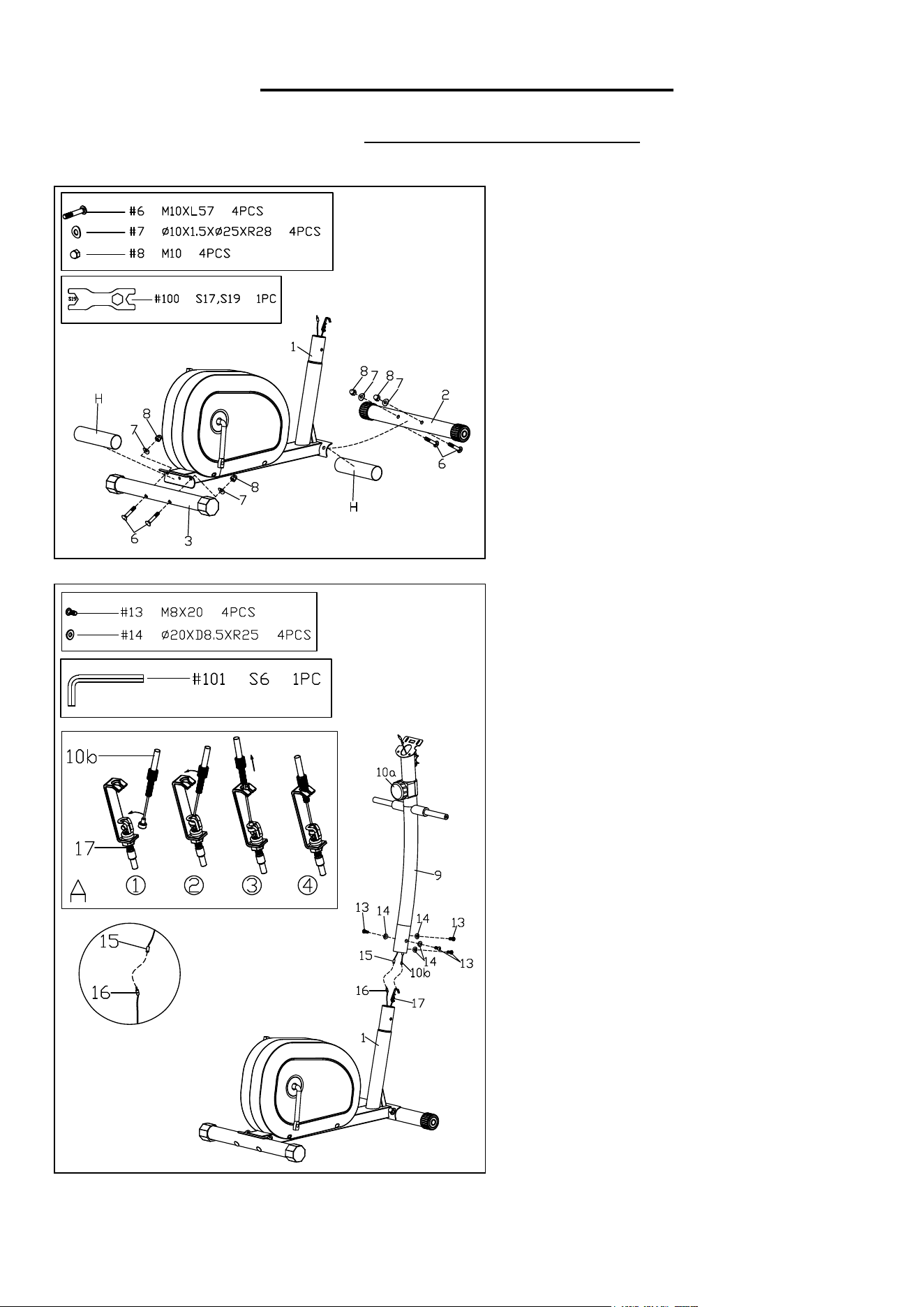
STEP 1:
Remove 2 Plastic Tubes (No. H) from the
Main Frame (No. 1).
Attach the Front Stabilizer (No. 2) and Rear
Stabilizer (No. 3) onto the Main Frame (No.
1), with 4 Carriage Bolts (No. 6), 4 Arc
Washers (No. 7) and 4 Domed Nuts (No. 8).
Tighten and secure with Spanner (No. 100).
NOTE: Ensure all bolts and washers are in
place and partially threaded in before
completely tightening them.
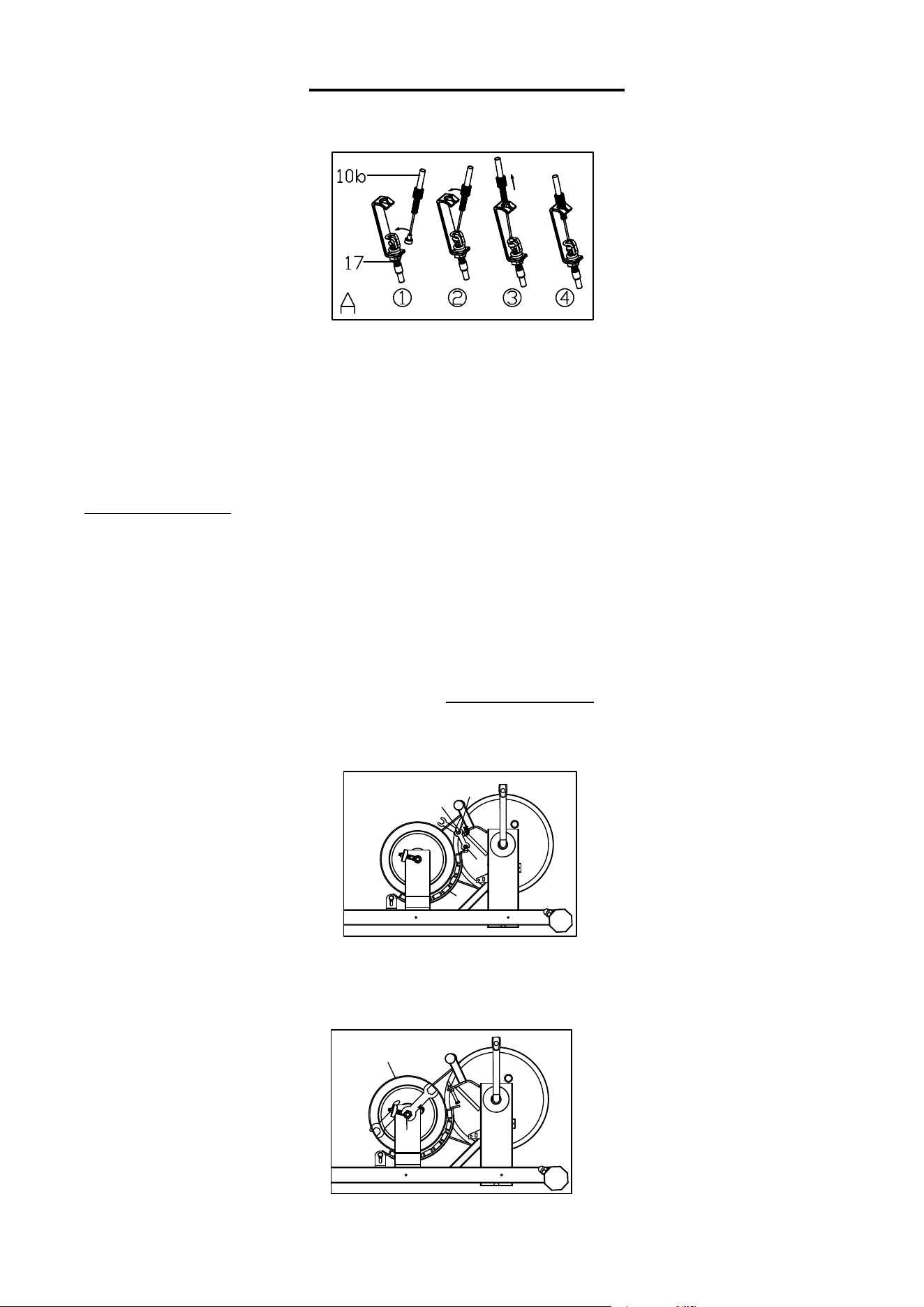
STEP 2:
Connect the Lower Sensor Wire (No. 16) with
the Upper Sensor Wire (No. 15), a
nd then
connect Tension Hook (No. 17) with Tension
Cable (No. 10b) as shown in Diagram A.
NOTE: Make sure the Tension Controller
(No. 10a) is at the lowest level before you
connect the Tension Cable (No. 10b). This
ensures the wires are at their longest point. We
recommend the assistance of a second person
to help hold the Handlebar Post (No. 9). This
will make attaching the Tension Hook (No. 17)
to the Tension Cable (No. 10b) easier.
Remove 4 Allen Bolts (No. 13) and 4
Arc
Washers (No. 14) from the Main Frame (No.
1) with Allen Wrench (No. 101). Insert the
Handlebar Post (No. 9) into the post of the
Main Frame (No. 1) secure with the 4 Allen
Bolts (No. 13) and 4 Arc Washers (No. 14)
that were just removed. Tighten and secure
with Allen Wrench (No. 101).
NOTE: Ensure that all bolts and washers are in
place and partially
threaded in before
completely tightening them.
5
We value your experience using Sunny Health and Fitness products. For assistance with parts or
troubleshooting, please contact us at support@sunnyhealthfitness.com or 1-877-90SUNNY
(877-907-8669).
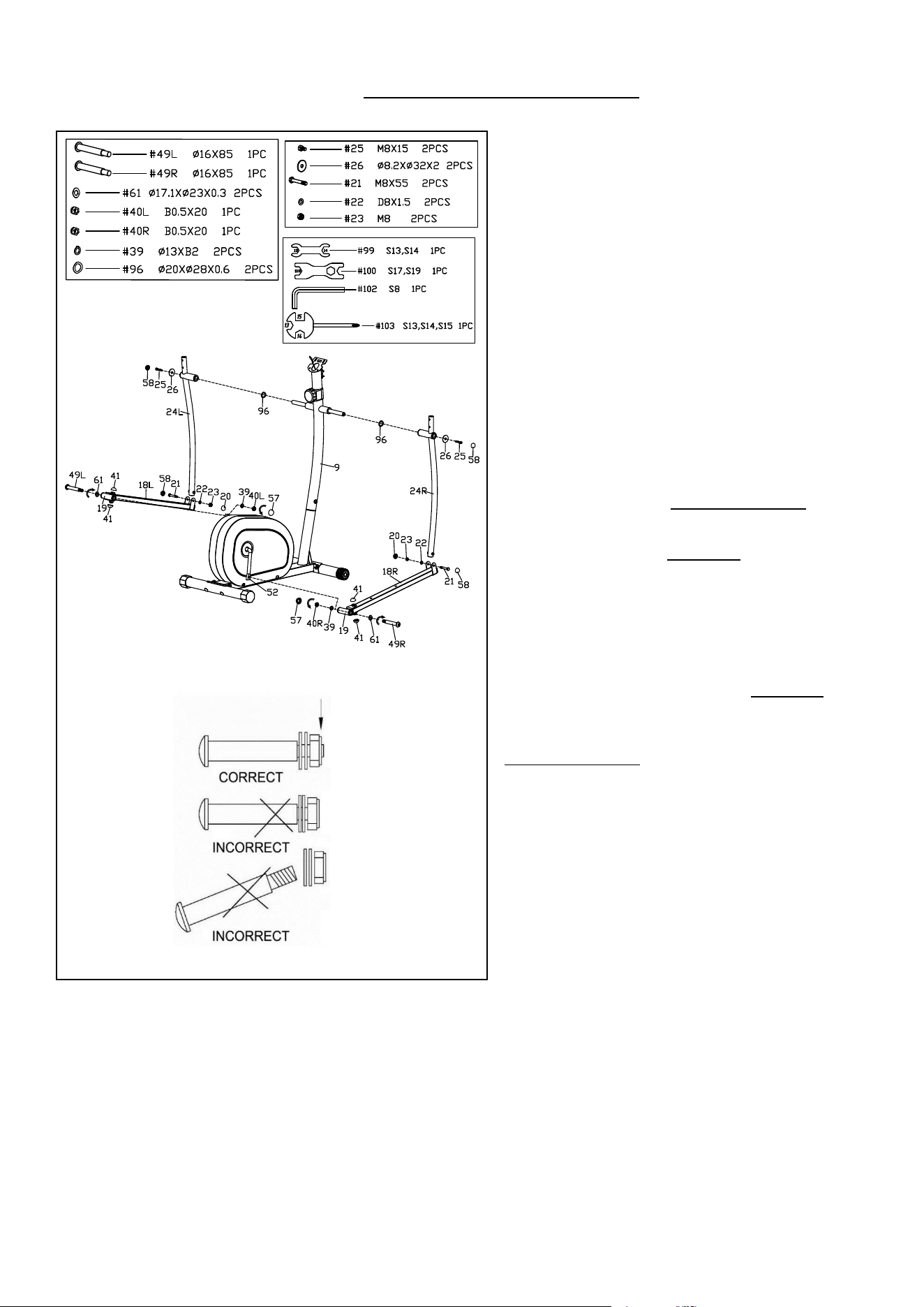
STEP 3:
Remove 2 Wave Washers (No. 96), 2 Hex Bolts
(No. 25) and 2 Flat Washers (No. 26) from the
long axle of the Handlebar Post (No. 9) with
Spanner (No. 103).
Attach 2 Wave Washers (No. 96) to the two
sides of the long axle on the Handlebar Post
(No. 9). Then attach the Left & Right Swing
Bars (No. 24L & No. 24R) to the two sides of the
long axle on the Handlebar Post (No. 9) with 2
Hex Bolts (No. 25) and 2 Flat Washers (No. 26)
that were just removed. Tighten and secure wit
h
Spanner (No. 103).
NOTE: Please do not fully tighten at this time.
Attach the Connecting Joint (No. 19) on the Left
Pedal Support Tube (No. 18L) to the left side of
Crank Arm (No. 52) with 1 Left Hinge Bolt (No.
49L), 1 Wave Washer (No. 61). Turn the Left
Hinge Bolt (No. 49L) counter-clockwise as tightly
as you can with your hand. Secure by tightening 1
Spring Washer (No. 39) and 1 BLACK color Left
Nylon Nut (No. 40L) clockwise. Then use Allen
Wrench (No. 102) and Spanner (No. 100) to
tighten securely.
Attach the Connecting Joint (No. 19) on the
Right Pedal Support Tube (No. 18R) to the right
side of Crank Arm (No. 52) with 1 Right Hinge
Bolt (No. 49R), 1 Wave Washer (No. 61). Turn
the Right Hinge Bolt (No. 49R) clockwise as
tightly as you can with your hand. Secure by
tightening 1 Spring Washer (No. 39) and 1
WHITE color Right Nylon Nut (No. 40R)
counter-clockwise. Then use Allen Wrench (No.
102) and Spanner (No. 100) to tighten securely.
NOTE: Please do not fully tighten at this time.
Please attach the Left & Right Hinge Bolts (No.
49L & No. 49R) correctly as shown in Fig.1.
Remove 2 Hex Bolts (No. 21), 2 Flat Washers
(No. 22) and 2 Nylon Nuts (No. 23) from Left &
Right Pedal Support Tubes (No. 18L & No.
18R) using Spanner (No. 103) and Spanner (No.
99). Then attach the Left & Right Swing Bars
(No. 24L & No. 24R) to the Left & Right Pe
dal
Support Tubes (No. 18L & No. 18R) with 2 Hex
Bolts (No. 21), 2 Flat Washers (No. 22) and 2
Nylon Nuts (No. 23) that were just removed.
Tighten and secure with Spanner (No. 103) and
Spanner (No. 99).
NOTE: If fail to screw in Hex Bolts (No. 21),
please move the Crank Arm (No. 52) to a
different angle and retry it.
Tighten 2 Hex Bolts (No. 25) and Left & Right
Nylon Nuts (No. 40L & No. 40R) tightly now.
Then cover with the 12 Nut Caps (No. 20 & No.
58
& No. 57 & No. 41).
Fig.1
6
We value your experience using Sunny Health and Fitness products. For assistance with parts or
troubleshooting, please contact us at support@sunnyhealthfitness.com or 1-877-90SUNNY
(877-907-8669).
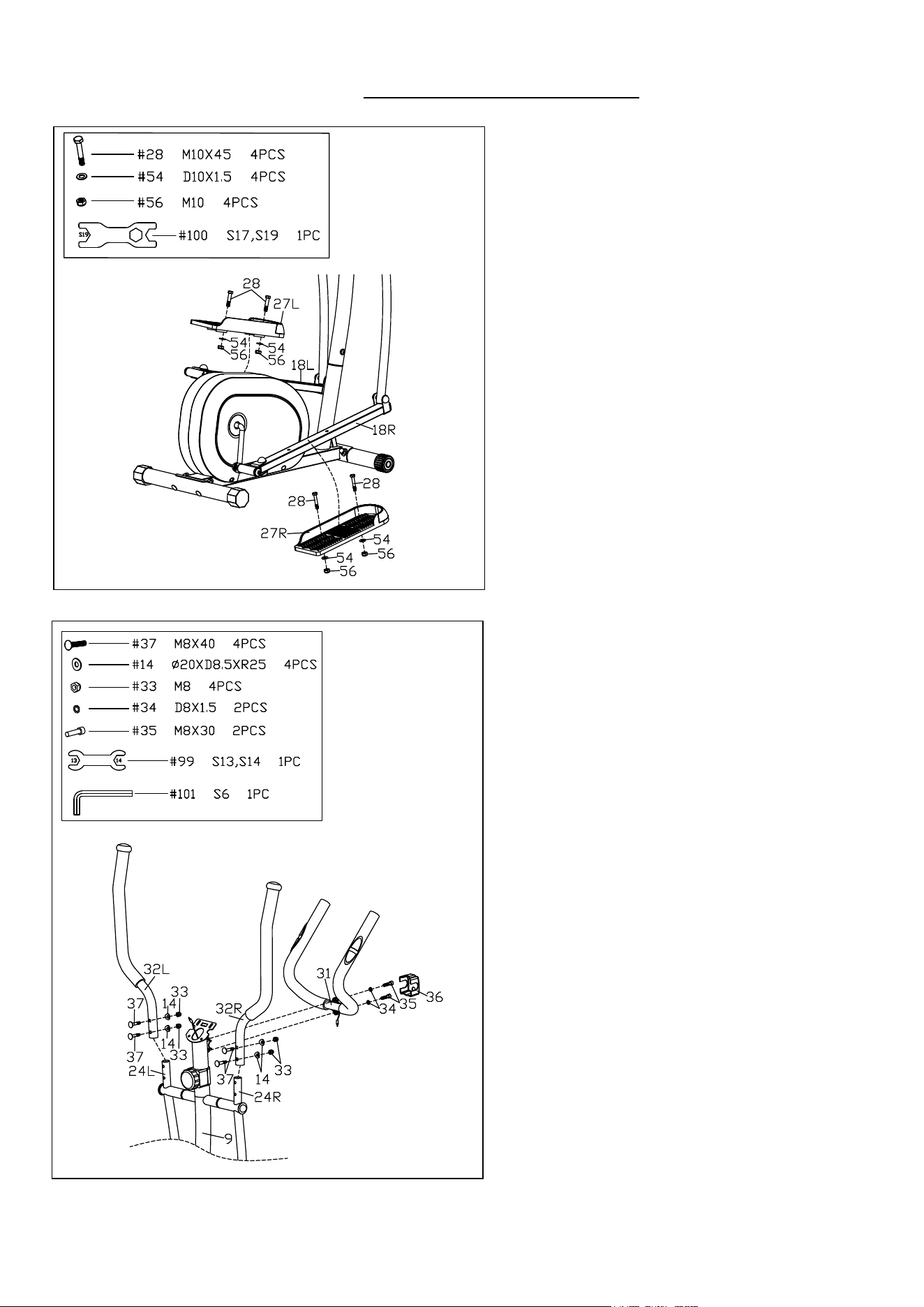
STEP 4:
Secure the Left & Right Pedals (No. 27L &
No. 27R) to the Left & Right Pedal
Support Tubes (No. 18L & No. 18R)
respectively using 4 Hex Bolts (No. 28), 4
Flat Washers (No. 54) and 4 Nylon Nuts
(No. 56).
Tighten and secure with Spanner
(No. 100).
NOTE: Both pedals are labeled L and R; L
for LEFT and R for RIGHT.
STEP 5:
Attach Armrest (No. 31) to the Handlebar
Post (No. 9). Secure with 2 Spring
Washers (No. 34) and 2 Hex Bolts (No.
35) using Allen Wrench (No. 101). Finally
attach the Decorative Cover (No. 36) onto
the
Armrest (No. 31).
Attach the Left & Right Handlebars (No.
32L & No. 32R) onto the Left & Right
Swing Bars (No. 24L & No. 24R) with 4
Carriage Bolts (No. 37), 4 Arc Washers
(No. 14) and 4 Domed Nuts (No. 33).
Tighten and secure with Spanner (No. 99).
NOTE: If the Left & Right Handlebars (No.
32L & No. 32R) rubs against the Armrest
(No. 31) during the workout, please recheck
if the Left & Right Handlebars (No. 32L &
No. 32R) is assembled to Left & Right
Swing Bars (No. 24L & No. 24R)
according to the label marked with L or R.
7
We value your experience using Sunny Health and Fitness products. For assistance with parts or
troubleshooting, please contact us at support@sunnyhealthfitness.com or 1-877-90SUNNY
(877-907-8669).
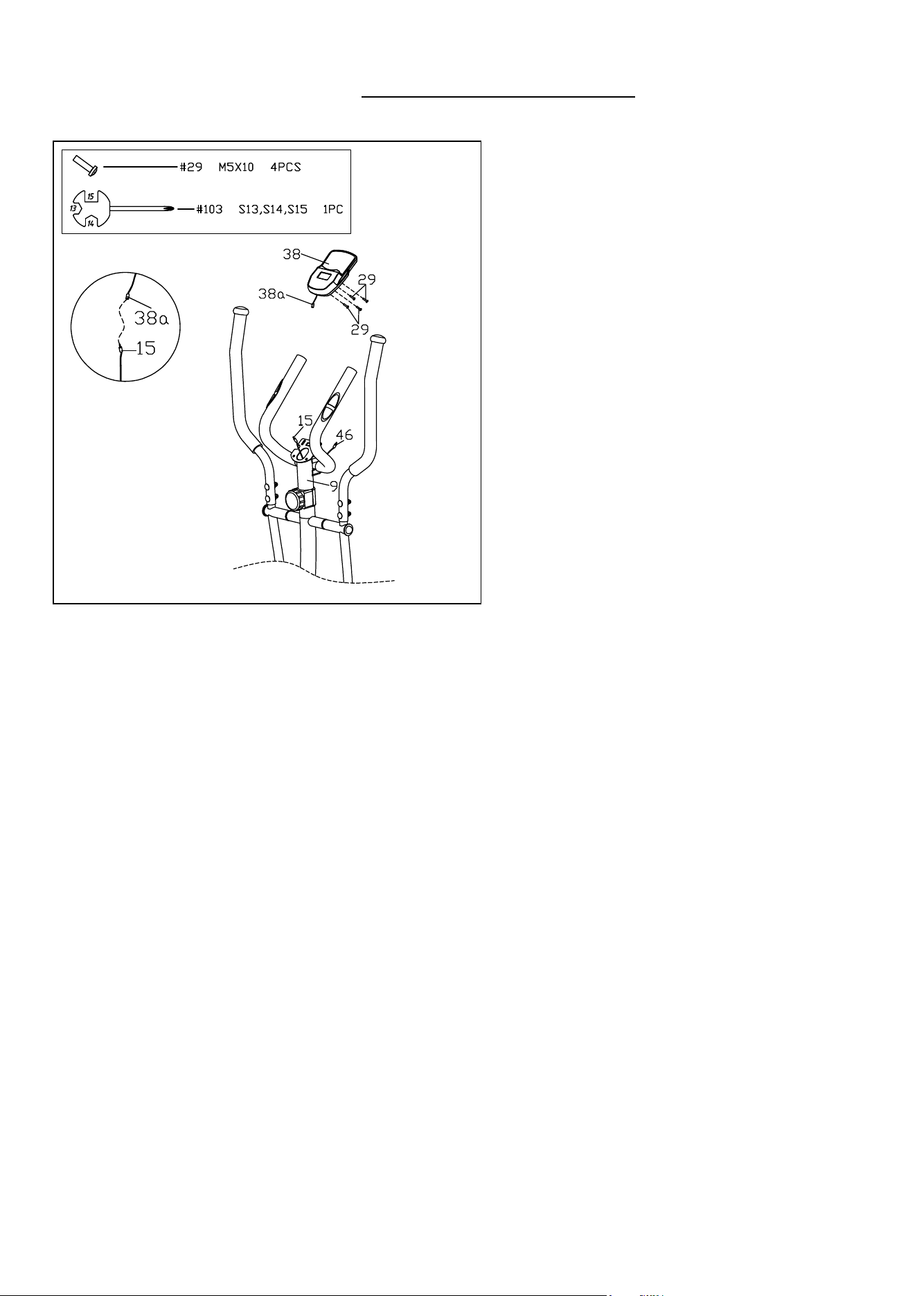
STEP 6:
Remove 4 Phillips Screws (No. 29) from
the Meter (No. 38) with Spanner (No. 103).
Plug the Pulse Sensor Wire (No. 46) to the
jack on the back of the Meter (No. 38). Then
connect the Upper Sensor Wire (No. 15) to
the Meter Wire (No. 38a).
Attach the Meter (No. 38) to the bracket of
the Handlebar Post (No. 9) using 4 Phillips
Screws (No. 29) that were just removed.
Tighten and secure with Spanner (No. 103).
NOTE: To avoid damaging the wires, please
push them into the Handlebar Post (No.
9)
before securing the Meter (No. 38) onto the
bracket.
THE ASSEMBLY IS COMPLETE!
8
TROUBLESHOOTING
1. If you find there is no difference between tension level 1 to level 8, please check the connection
of the tension cable. Please see Diagram A under STEP 2.
2. If the meter does not show numbers correctly, please check the batteries. If the meter does not
count the speed and time, please check the connections of Upper Sensor Wire (No. 15) to the
Meter Wire (No. 38a), and Upper Sensor Wire (No. 15) to Lower Sensor Wire (No. 16).
3.
If you have difficulty in putting Left & Right Hinge Bolts (No. 49L & No. 49R)
into
the Crank
Arm (No. 52), or putting Hex Bolts (No. 21) into Left & Right Pedal Support Tubes (No. 18L
& No. 18R), please try moving the Crank Arm (No. 52) to a different angle. *Keep in mind the
Left Hinge Bolt (No. 49L) has reversed threading and must be installed by turning
counter-clockwise.
4. If you hear any noise when using the machine, please check if Left & Right Hinge Bolts (No.
49L & No. 49R), Hex Bolts (No. 21), Hex Bolts (No. 25) and Connecting Joints (No. 19) are
loose. You may remove these parts and add some lubricant oil to eliminate all noise possibilities.
Remember to tighten all the parts securely.
5. If it is very hard to pedal on the higher tension levels, or you hear rubbing noises, please
remove the Left & Right Belt Covers (No. 105L & No. 105R), and adjust the Hex Bolt (No. 77)
seen in the following diagram.
You will need to loosen the 2 Hex Nuts (No. 78) and lower the
position of the Hex Bolt (No. 77) by turning counter-clockwise. This will keep the Magnetic
Board (No. 84) from making contact with the magnetic flywheel. Before re-installing the Left &
Right Belt Covers (No. 105L & No. 105R), test the tension level 8 to ensure the magnets do
not touch the flywheel.
6. If you still hear noises after you did STEP 4 and STEP 5, please remove the Left & Right Belt
Covers (No. 105L & No. 105R). Loosen the Hex Thin Nut (No. 87) for the Flywheel (No. 94)
about a half of a rotation. See the following diagram below.
7. If the machine is wobbly when you use it, please consi
der adding an exercise mat under it.
77
78
78
84
94
87
9
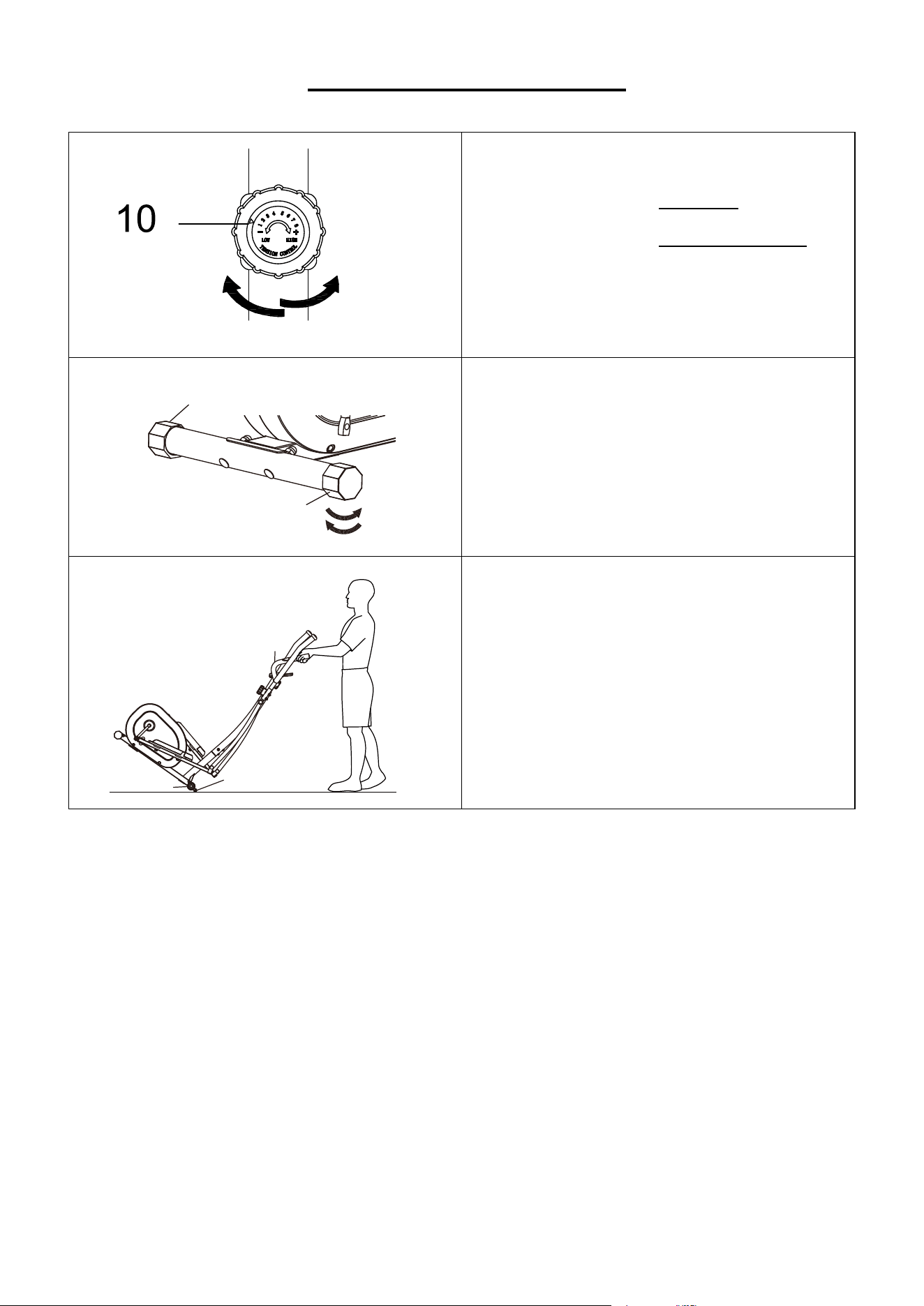
ADJUSTMENT GUIDE
ADJUSTING THE TENSION
Adjust the tension by rotating the Tension
Controller (No. 10a) clockwise to increase
the level of resistance. Rotate the Tension
Controller (No. 10a) counter-clockwise to
decrease the level of resistance.
Tension levels are set at Level 1 being the
lowest and Level 8 being the highest.
ADJUSTING THE LEVEL
If at any point the bike does not feel level,
you can adjust the Leveler Caps (No. 5).
HOW TO MOVE THE ELLIPTICAL
There are Transportation Wheels (No. 65)
located on the Front Stabilizer (No. 2). Hold
the Armrest (No. 31) and push down the
front of the elliptical until the Transportation
Wheels (No. 65) touch the ground. Now you
can move the elliptical.
2
65
31
5
5
a
10
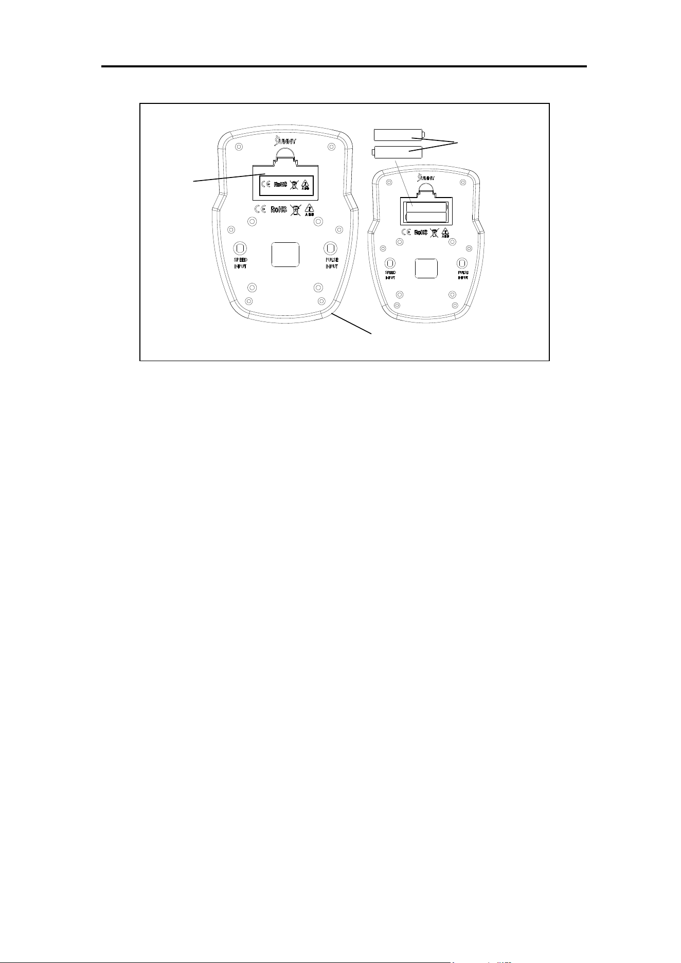
BATTERY INSTALLATION & REPLACEMENT
BATTERY INSTALLATION
1. Take out 2 AAA batteries from meter box.
2. Press the buckle of battery cover on the Meter (No. 38), then remove battery cover.
3. Install 2 AAA batteries into the battery case on the back of the Meter (No. 38). Pay attention to
the battery + and – poles before installing.
4. Press the buckle of battery cover, then put the battery cover back to the back of the Meter (No.
38).
The installation is complete!
BATTERY REPLACEMENT
1. Press the buckle of battery cover on the back of the Meter (No. 38), then remove battery cover.
2. Remove the 2 old AAA batteries in the battery case and install 2 new AAA batteries into the
battery case on the back of the Meter (No. 38). Pay attention to the battery + and – poles before
installing.
3. Press the buckle of battery cover, then put the battery cover back to the back of the Meter (No.
38).
The replacement is complete!
BATTERY DISPOSAL
Dispose the batteries according to the laws and regulations of your local region. Some batteries
may be recycled. When disposing or recycling, do not mix battery types.
Battery
Battery
Cover
38
11
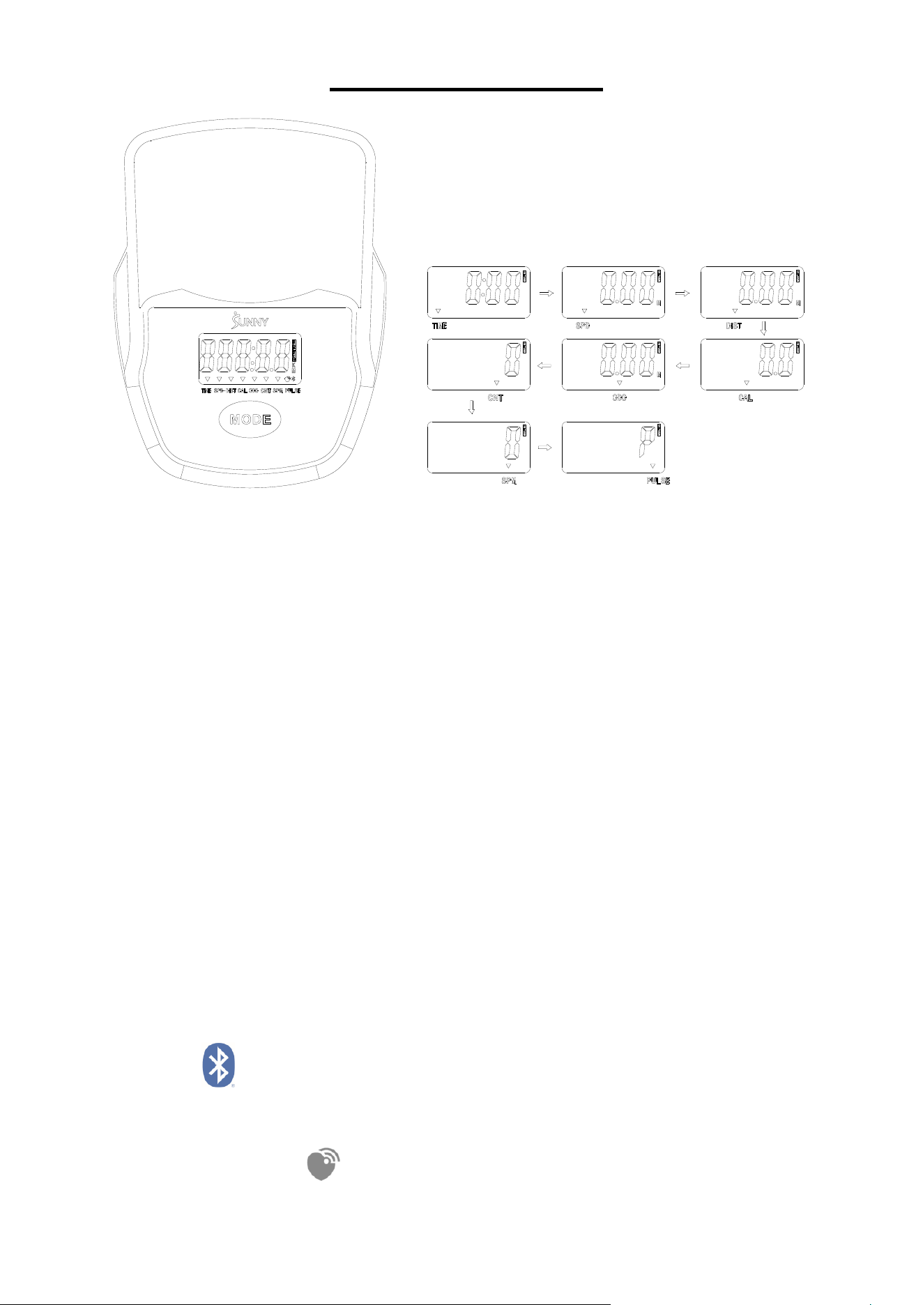
EXERCISE METER
■MODE KEY FUNCTION
This key lets you select and lock on to a particular function you want.
SCAN→TIME→SPD (SPEED)→DIST (DISTANCE)→CAL (CALORIES)→ODO (TOTAL
DISTANCE)→CNT (COUNT)→SPM →PULSE
Press and hold for 3 seconds to reset all the values, except ODO (TOTAL DISTANCE), to zero
when Bluetooth is not connected.
Press and hold for 6 seconds to disconnect from both the SunnyFit APP and the heart rate
monitor; then, the meter will enter sleep mode.
■SLEEP MODE
The meter will shut off automatically and disconnect the heart rate monitor if there is no activity
or no keys are pressed for approximately 4 minutes.
The meter will turn back on when the MODE key is pressed, or there is activity.
■FUNCTION
SCAN: Meter will rotate through all functions every 6 seconds.
TIME: Counts the total time from start to finish.
SPD (SPEED): Displays the current speed.
DIST (DISTANCE): Counts the distance of an exercise from start to finish.
CAL (CALORIES): Counts total calories burned during exercise from start to finish.
ODO (TOTAL DISTANCE): Counts the total distance from when batteries were installed. If the
batteries are replaced, the value resets to zero.
CNT (COUNT): Displays the turns from start to finish.
SPM: The average number of turns per minute of the wheel to measure the speed of the pedal.
PULSE: The current pulse rate.
BLUETOOTH :
1. The Bluetooth icon will flash when the meter is on or wakes from sleep mode. If no Bluetooth
connection is established within 3 minutes, the Bluetooth icon will turn off.
2. The Bluetooth icon will stay on when it is connected.
WIRELESS HEART RATE :
1. Wireless heart rate icon will flash when the meter is on. If the heart rate monitor is not
connected within 1 minute, the wireless heart rate icon will turn off.
12
2. After exercise resumes, the wireless heart rate icon will flash. If the heart rate monitor is not
connected within 1 minute, the wireless heart rate icon will turn off.
3. When the meter wakes from sleep mode, the wireless heart rate icon will flash. If the heart
rate monitor is not connected within 1 minute, the wireless heart rate icon will turn off.
4. The wireless heart rate icon will flash when the MODE key is pressed during exercise. If the
heart rate monitor is not connected within 1 minute, the wireless heart rate icon will turn off.
5. The wireless heart rate icon will stay on when the heart rate monitor is connected.
NOTE: The heart rate monitor is not included. Wireless heart rate function works with SunnyFit
Heart Rate Monitor HR200.
■SPECIFICATIONS
APP CONNECTION:
Connect Smart Equipment to SunnyFit App:
1. Scan to download SunnyFit from the app store:
2. Ensure that the Bluetooth function is turned on from your mobile device.
3. If this is your first time using the SunnyFit app, follow the in-app instructions to register for your
free SunnyFit account and log in.
4. Begin any workout activity that matches your smart equipment, then follow the onscreen
prompts to search for and connect to your smart equipment.
5. When connected, your stats and records will be displayed at the end of your course/session and
recorded in your account profile!
Troubleshooting:
If you are having trouble connecting your smart equipment, visit www.sunnyfit.com/guide or
scan the QR code below:
If you require additional support, please contact [email protected].
FUNCTION
SCAN
6S
TIME
00:00-999:59 (M:S)
SPD (SPEED)
0.00~99.99 MPH
DIST (DISTANCE)
0.00~9999.9 MILE
ODO (TOTAL DISTANCE)
0.00~9999.9 MILE
CAL (CALORIES)
0.0~9999.9 CAL
CNT
0~99999
SPM
0~399
PULSE
40~240 BPM
BATTERY
SIZE-AAA, 2PCS
OPERATING TEMPERATURE
0~40℃ (32℉-104℉)
STORAGE TEMPERATURE
-10~60℃ (14℉-140℉)
13
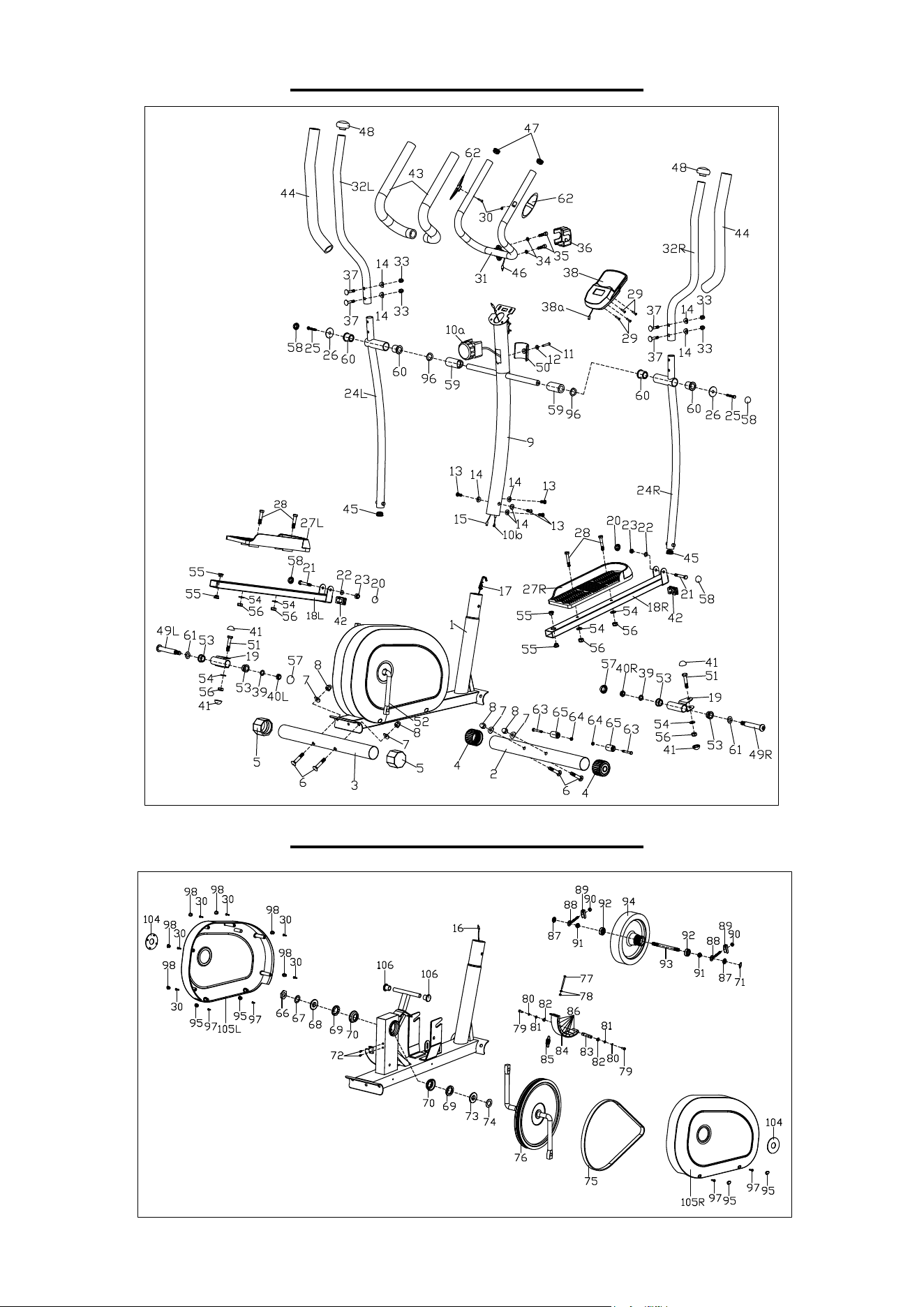
EXPLODED DIAGRAM 1
EXPLODED DIAGRAM 2

14
PARTS LIST
No.
Description
Spec.
Qty.
No.
Description
Spec.
Qty.
1
Main Frame
1
45
Round End Cap
Φ28X1.5
2
2
Front Stabilizer
1
46
Pulse Sensor Wire
600mm
2
3
Rear Stabilizer
1
47
Spherical Cap
Φ25X1.5
2
4
End Cap
Φ50X1.5
2
48
Mushroom Cap
Φ28.6X1.5
2
5
Leveler Cap
Φ50X1.5
2
49L
Left Hinge Bolt
Φ16X85
1
6
Carriage Bolt
M10XL57
4
49R
Right Hinge Bolt
Φ16X85
1
7
Arc Washer
Φ10X1.5XΦ25XR28
4
50
Tension Controller
Cover
1
8
Domed Nut
M10
4
51
Hex Bolt
M10X50
2
9
Handlebar Post
1
52
Crank Arm
L140XW228
1
10a
Tension Controller
8-level
1
53
Axle Bushing 1
Φ24X16XΦ16.1
4
10b
Tension Cable
L590
1
54
Flat Washer
D10X1.5
6
11
Phillips Screw
M5X45
1
55
Alloy Bushing
Φ14X12.5XΦ10.1
4
12
Flat Washer
D5
1
56
Nylon Nut
M10
6
13
Allen Bolt
M8X20
4
57
Nut Cap
S19
2
14
Arc Washer
Φ20XD8.5XR25
8
58
Nut Cap
S14
4
15
Upper Sensor Wire
900mm
1
59
Spacer
Φ32X59
2
16
Lower Sensor Wire
1200mm
1
60
Axle Bushing 2
Φ32X2.5
4
17
Tension Hook
1300mm
1
61
Wave Washer
Φ17.1XΦ23X0.3
2
18L
Left Pedal Support
Tube
1
62
Pulse Sensor
2
18R
Right Pedal Support
Tube
1
63
Hex Bolt
M6XL45
2
19
Connecting Joint
2
64
Nylon Nut
M6
2
20
Nut Cap
S13
2
65
Transportation Wheel
Φ23X32XΦ6
2
21
Hex Bolt
M8X55
2
66
Nut
4.5X32X32
1
22
Flat Washer
D8X1.5
2
67
Washer
Φ22.6XΦ28X2.5
1
23
Nylon Nut
M8
2
68
Locking Nut-L
Φ45XH3.5XΦ33.5
1
24L
Left Swing Bar
1
69
Open Face Bearing
Φ45.8X8.8
2
24R
Right Swing Bar
1
70
Bearing Housing
δ2.5X76X76
2
25
Hex Bolt
M8X15
2
71
Plastic Nut
S17
1
26
Flat Washer
Φ8.2XΦ32X2
2
72
Phillips Screw
ST3X10
2
27L
Left Pedal
1
73
Locking Nut-R
Φ45XH3.5XΦ33.5
1
27R
Right Pedal
1
74
Big Washer
Φ25.2XΦ38X1
1
28
Hex Bolt
M10X45
4
75
Belt
380PJ6
1
29
Phillips Screw
M5X10
4
76
Belt Pulley
Φ260X20
1
30
Phillips Screw
ST4.2X18
8
77
Hex Bolt
M5XL60
1
31
Armrest
1
78
Hex Nut
M5
2
32L
Left Handlebar
1
79
Hex Bolt
M6XL15
2
32R
Right Handlebar
1
80
Spring Washer
D6
2
33
Domed Nut
M8
4
81
Flat Washer
D6
2
34
Spring Washer
D8X1.5
2
82
Axle Stop Ring
D12
2
35
Hex Bolt
M8X30
2
83
Magnetic Board Axle
Φ12X50
1
36
Decorative Cover
1
84
Magnetic Board
1
37
Carriage Bolt
M8X40
4
85
Spring
61XΦ15XΦ1.6
1
38
Meter
BJHT060
1
86
Square Magnet
40X25X10
8
38a
Meter Wire
150mm
1
87
Hex Thin Nut
M10X1
2
39
Spring Washer
Φ13XB2
2
88
Adjusting Belt Bolt
M6X50
2
40L
Left Nylon Nut
B0.5X20
1
89
Adjusting U Washer
3X30X20
2
40R
Right Nylon Nut
B0.5X20
1
90
Hex Nut
M6
2
41
Nut Cap
S17
4
91
Nut
M10X1.0
2
42
Square End Cap
40X25X1.5
2
92
Bearing
6000z
2
43
Foam Grip
Φ23XΦ32X480
2
93
Flywheel Axle
Φ10XM10X1XL118
1
44
Foam Grip
Φ26XΦ36X480
2
94
Flywheel
Φ200X38
1

15
Version: 1.1
No.
Description
Spec.
Qty.
No.
Description
Spec.
Qty.
95
Belt Cover Plug
4
102
Allen Wrench
S8
1
96
Wave Washer
Φ20XΦ28X0.6
2
103
Spanner
S13,S14,S15
1
97
Phillips Screw
ST5X20
4
104
Crank Cover
2
98
Round Plug
6
105L
Left Belt Cover
1
99
Spanner
S13,S14
1
105R
Right Belt Cover
1
100
Spanner
S17,S19
1
106
Plug
Φ13X1.5
2
101
Allen Wrench
S6
1