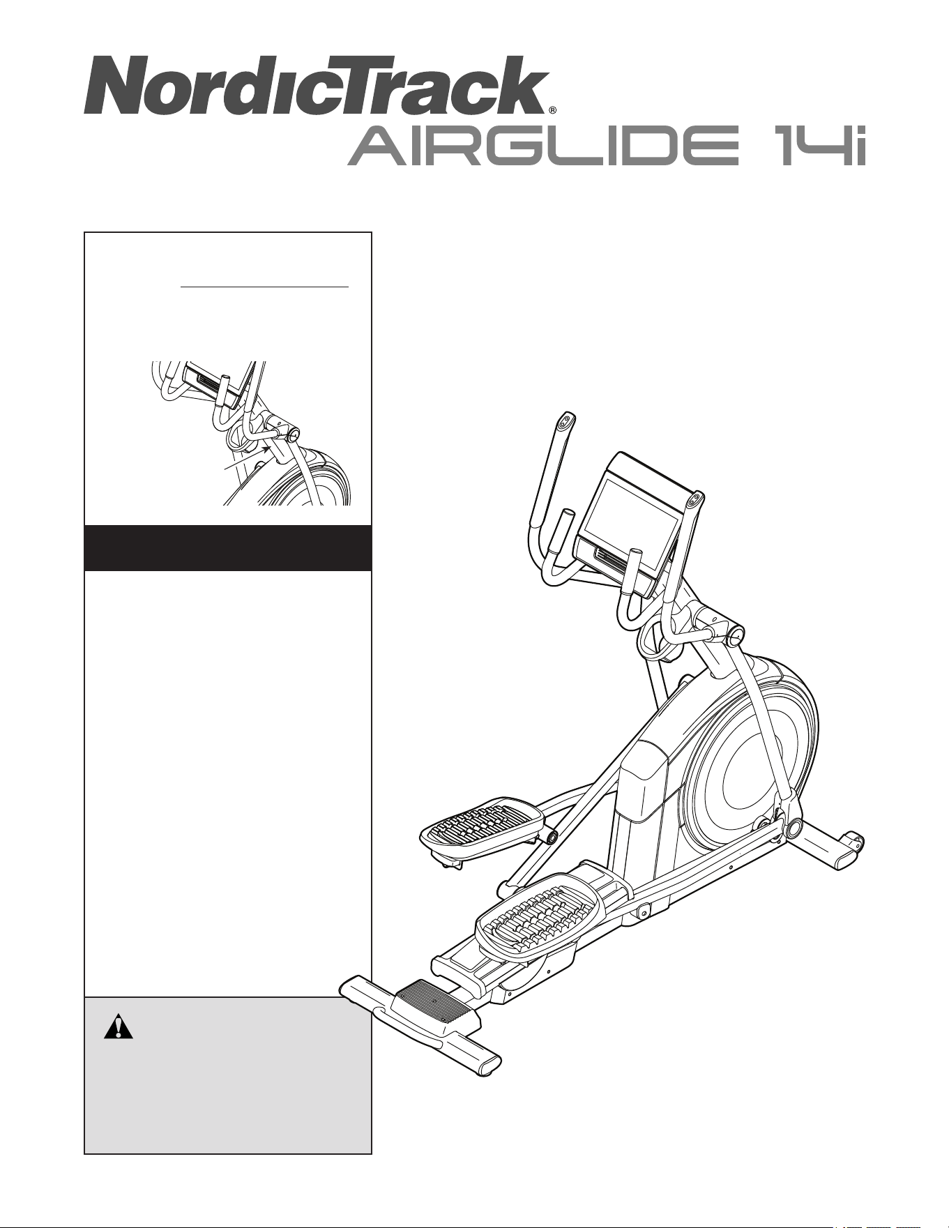
USER’S MANUAL
Serial Number
Decal
CAUTION
Read all precautions and
instructions in this manual before
using this equipment. Keep this
manual for future reference.
Model No. NTEL71423-INT.2
Serial No.
Write the serial number in the space
above for reference.
iconeurope.com
MEMBER CARE
UNITED KINGDOM
Website: iFITsupport.eu
E-mail: [email protected]
Write:
iFIT Health & Fitness Limited
Unit 4, Westgate Court
Silkwood Park
OSSETT
WF5 9TT
UNITED KINGDOM
AUSTRALIA
Call: 1800 993 770
E-mail: australiacc@iFIT.com
Write:
iFIT Inc.
PO Box 635
WINSTON HILLS NSW 2153
AUSTRALIA
2
TABLE OF CONTENTS
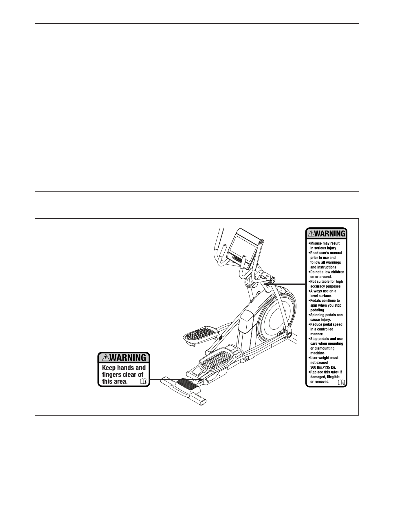
WARNING DECAL PLACEMENT
This drawing shows the location(s) of the warning
decal(s). If a decal is missing or illegible, see
the front cover of this manual and request a
free replacement decal. Apply the decal in the
location shown. Note: The decal(s) may not be
shown at actual size.
WARNING DECAL PLACEMENT . . . . . . . . . . . . . . . . . . . . . . . . . . . . . . . . . . . . . . . . . . . . . . . . . . . . . . . . . . . . . . .2
IMPORTANT PRECAUTIONS ..................................................................3
BEFORE YOU BEGIN. . . . . . . . . . . . . . . . . . . . . . . . . . . . . . . . . . . . . . . . . . . . . . . . . . . . . . . . . . . . . . . . . . . . . . . .5
PART IDENTIFICATION CHART. . . . . . . . . . . . . . . . . . . . . . . . . . . . . . . . . . . . . . . . . . . . . . . . . . . . . . . . . . . . . . . .6
ASSEMBLY . . . . . . . . . . . . . . . . . . . . . . . . . . . . . . . . . . . . . . . . . . . . . . . . . . . . . . . . . . . . . . . . . . . . . . . . . . . . . . . .7
HOW TO USE THE ELLIPTICAL ..............................................................17
HOW TO USE THE CONSOLE. . . . . . . . . . . . . . . . . . . . . . . . . . . . . . . . . . . . . . . . . . . . . . . . . . . . . . . . . . . . . . . .20
MAINTENANCE AND TROUBLESHOOTING .....................................................32
EXERCISE GUIDELINES ....................................................................34
PART LIST. . . . . . . . . . . . . . . . . . . . . . . . . . . . . . . . . . . . . . . . . . . . . . . . . . . . . . . . . . . . . . . . . . . . . . . . . . . . . . . .35
EXPLODED DRAWING. . . . . . . . . . . . . . . . . . . . . . . . . . . . . . . . . . . . . . . . . . . . . . . . . . . . . . . . . . . . . . . . . . . . . .37
ORDERING REPLACEMENT PARTS .................................................. Back Cover
RECYCLING INFORMATION ......................................................... Back Cover
UK/EU DECLARATION OF CONFORMITY .............................................. Back Cover
NORDICTRACK and IFIT are registered trademarks of iFIT Inc. Google Maps is a trademark of Google LLC. The
Bluetooth
®
word mark and logos are registered trademarks of Bluetooth SIG, Inc. and are used under license.
Wi-Fi is a registered trademark of Wi-Fi Alliance. WPA and WPA2 are trademarks of Wi-Fi Alliance.
This decal is
on both sides

3
IMPORTANT PRECAUTIONS
WARNING: To reduce the risk of burns, fire, electric shock, or injury to persons, read
all important precautions and instructions in this manual and all warnings on your elliptical before
using your elliptical. iFIT assumes no responsibility for personal injury or property damage sus-
tained by or through the use of this product.
1. It is the responsibility of the owner to ensure
that all users of the elliptical are adequately
informed of all precautions.
2. Keep children under age 16 and pets away
from the elliptical at all times.
3. Consult your health care provider before
beginning any exercise program. This is
especially important for persons over age 35
or persons with pre-existing health problems.
4. Consult your health care provider before
beginning or continuing any exercise pro-
gram during pregnancy. Use the elliptical
only as authorized by your health care
provider.
5. The elliptical is not intended for use by
persons with reduced physical, sensory, or
mental capabilities or lack of experience and
knowledge, unless they are given supervi-
sion or instruction about use of the elliptical
by someone responsible for their safety.
6. Use the elliptical only as described in this
manual.
7. The elliptical is intended for home use only.
Do not use the elliptical in a commercial,
rental, or institutional setting.
8. Keep the elliptical indoors, away from mois-
ture and dust. Do not put the elliptical in a
garage or covered patio, or near water.
9. Place the elliptical on a level surface, with at
least 3 ft. (0.9 m) of clearance in the front and
rear of the elliptical and 2 ft. (0.6 m) on each
side. To protect the floor or carpet from dam-
age, place a mat under the elliptical.
10. Inspect and properly tighten all parts each
time the elliptical is used. Replace any worn
parts immediately. Use only manufacturer-
supplied parts.
11. When connecting the power cord, plug the
power cord into an earthed circuit.
12. Do not modify the power cord or use an
adapter to connect the power cord to an
improper receptacle. Keep the power cord
away from heated surfaces. Do not use an
extension cord.
13. Do not operate the elliptical if the power cord
or plug is damaged, or if the elliptical is not
working properly.
14. DANGER: Always unplug the power
cord and switch the power switch to the off
position when the elliptical is not in use and
before cleaning the elliptical. Servicing other
than the procedures in this manual should be
performed by an authorized service repre-
sentative only.
15. The elliptical should not be used by persons
weighing more than 300 lbs. (135 kg).
16. Wear appropriate clothes while exercising;
do not wear loose clothes that could become
caught on the elliptical. Always wear athletic
shoes for foot protection while exercising.
17. Hold the handlebars or the upper body arms
when mounting, dismounting, or using the
elliptical. Before mounting or dismounting,
bring the pedals to a stop with the pedal
on the mounting or dismounting side in its
lowest position.

4
SAVE THESE INSTRUCTIONS
18. The elliptical does not have a freewheel; the
pedals will continue to move until the fly-
wheel stops. Reduce your pedaling speed in
a controlled way.
19. Keep your back straight while using the
elliptical; do not arch your back.
20. Over exercising may result in serious injury
or death. If you feel faint, if you become short
of breath, or if you experience pain while
exercising, stop immediately and cool down.
5
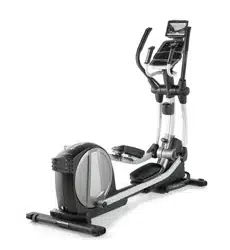
Thank you for selecting the revolutionary
NORDICTRACK
®
AIRGLIDE 14I elliptical. The
AIRGLIDE 14I elliptical provides an impressive selec-
tion of features designed to make your workouts at
home more effective and enjoyable.
For your benefit, read this manual carefully before
you use the elliptical. If you have questions after
reading this manual, please see the front cover of this
manual. To help us assist you, note the product model
number and serial number before contacting us. The
model number and the location of the serial number
decal are shown on the front cover of this manual.
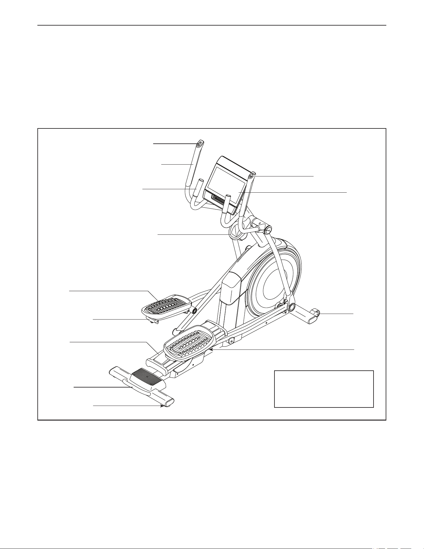
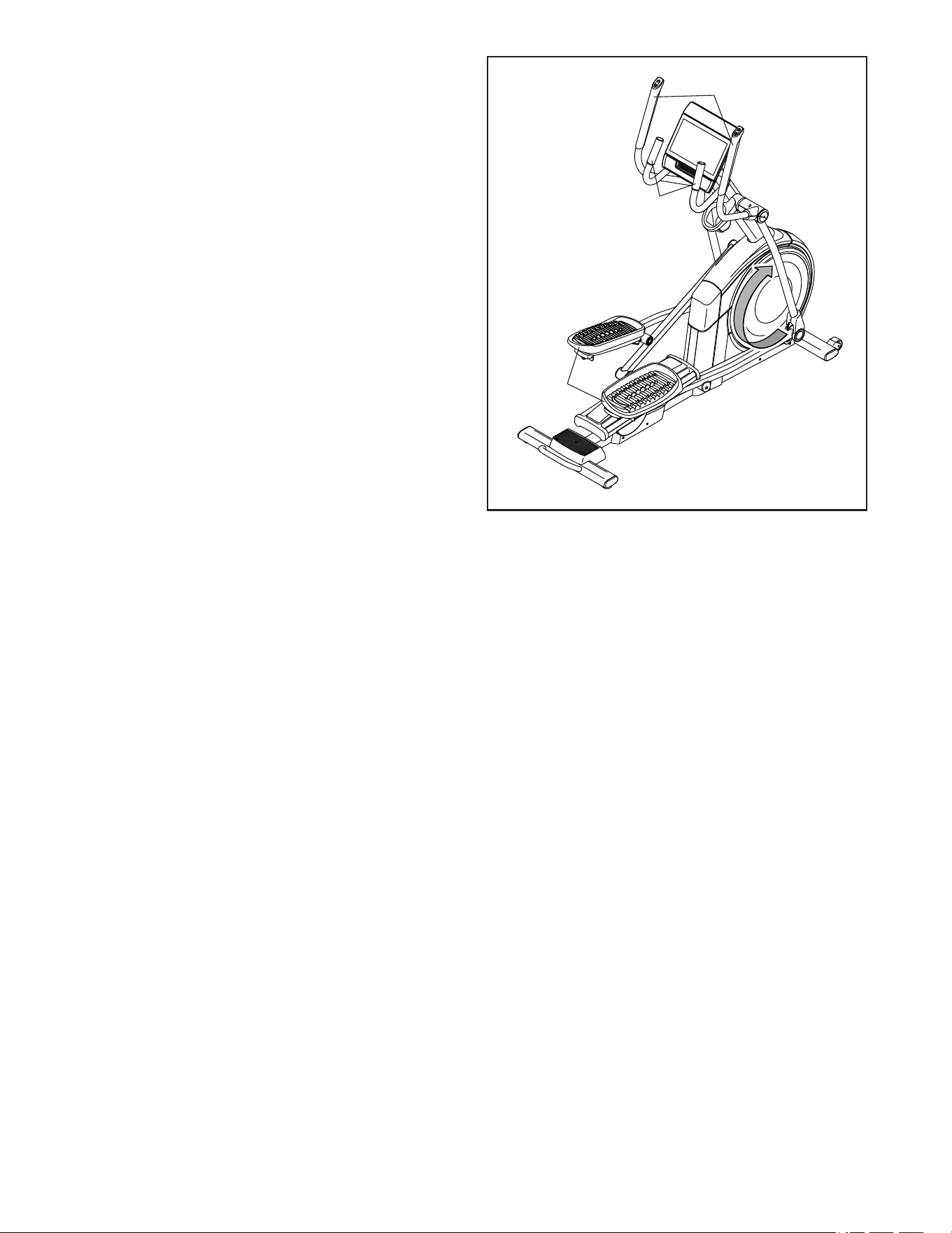
Before reading further, please familiarize yourself with
the parts that are labeled in the drawing below.
Accessory Tray
Handlebar
Upper Body Arm
Ramp Control
Pedal
Pedal Handle
Roller
Handle
Ramp
Console
Resistance Control
BEFORE YOU BEGIN
Wheel
Leveling Foot
Length: 5 ft. 11 in. (180 cm)
Width: 2 ft. 1 in. (64 cm)
Weight: 225 (102 kg)
6
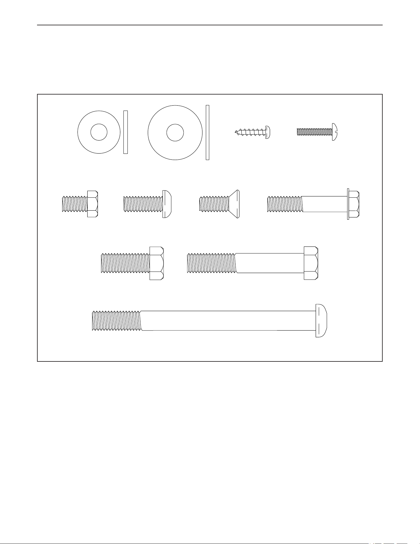
PART IDENTIFICATION CHART
Use the drawings below to identify the small parts needed for assembly. The number in parentheses below each
drawing is the key number of the part, from the PART LIST near the end of this manual. The number following
the key number is the quantity needed for assembly. Note: If a part is not in the hardware kit, check to see
whether it has been preassembled. Extra parts may be included.
M10 x 115mm Screw (104)–2
M8 x 13mm
Screw (82)–4
M8 x 20mm Flat
Head Screw (120)–2
M8 x 20mm
Screw (95)–2
M4 x 16mm
Screw (101)–16
M8 x 22mm
Washer (129)–2
M8 x 28mm
Washer (97)–2
M10 x 25mm
Screw (92)–2
M10 x 60mm Screw
(90)–4
M4 x 18mm
Machine Screw
(155)–3
M8 x 41mm Screw
(96)–4
7
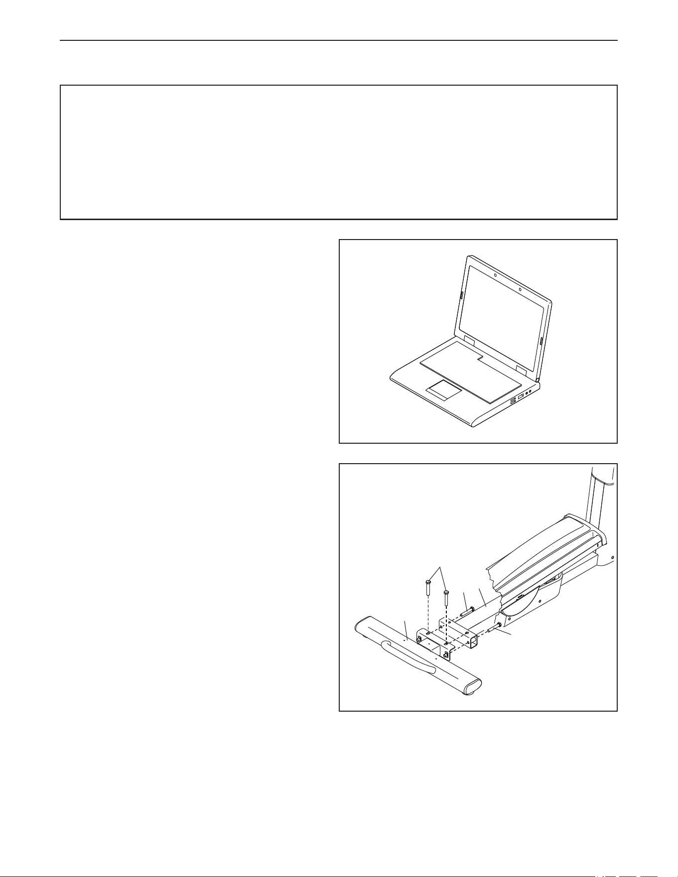
2. With the help of a second person, place some of
the packing materials (not shown) under the rear
of the Frame (1). Have the second person hold
the Frame to prevent it from tipping until you
complete this step.
If there are shipping supports attached to the
rear of the Frame (1), remove the screws from
the shipping supports, and discard the screws
and the shipping supports.
Next, attach the Rear Stabilizer (2) to the Frame
(1) with four M10 x 60mm Screws (90).
Then, remove the packing materials from under
the Frame (1).
2
1
2
90
90
ASSEMBLY
90
1
1. To register your product and activate your
warranty in the UK, go to iconsupport.eu. If you
do not have internet access, call Member Care
(see the front cover of this manual).
To register your product and activate your
warranty in Australia, email or post the
following information to the email address or
postal address on the front cover of this manual.
• your receipt (make sure to keep a copy)
• your name, address, and telephone number
• the model number, serial number, and name
of your product (see the front cover of this
manual)
• Assembly requires two persons.
• Place all parts in a cleared area and remove the
packing materials. Do not dispose of the packing
materials until you nish all assembly steps.
• Left parts are marked “L” or “Left” and right parts
are marked “R” or “Right.”
• To identify small parts, see page 6.
• Assembly can be completed using the included
tools. Note: Keep the included tools. One or more
of the tools may be needed to make adjustments
in the future. To avoid damaging parts, do not use
power tools for assembly or adjustment.
8
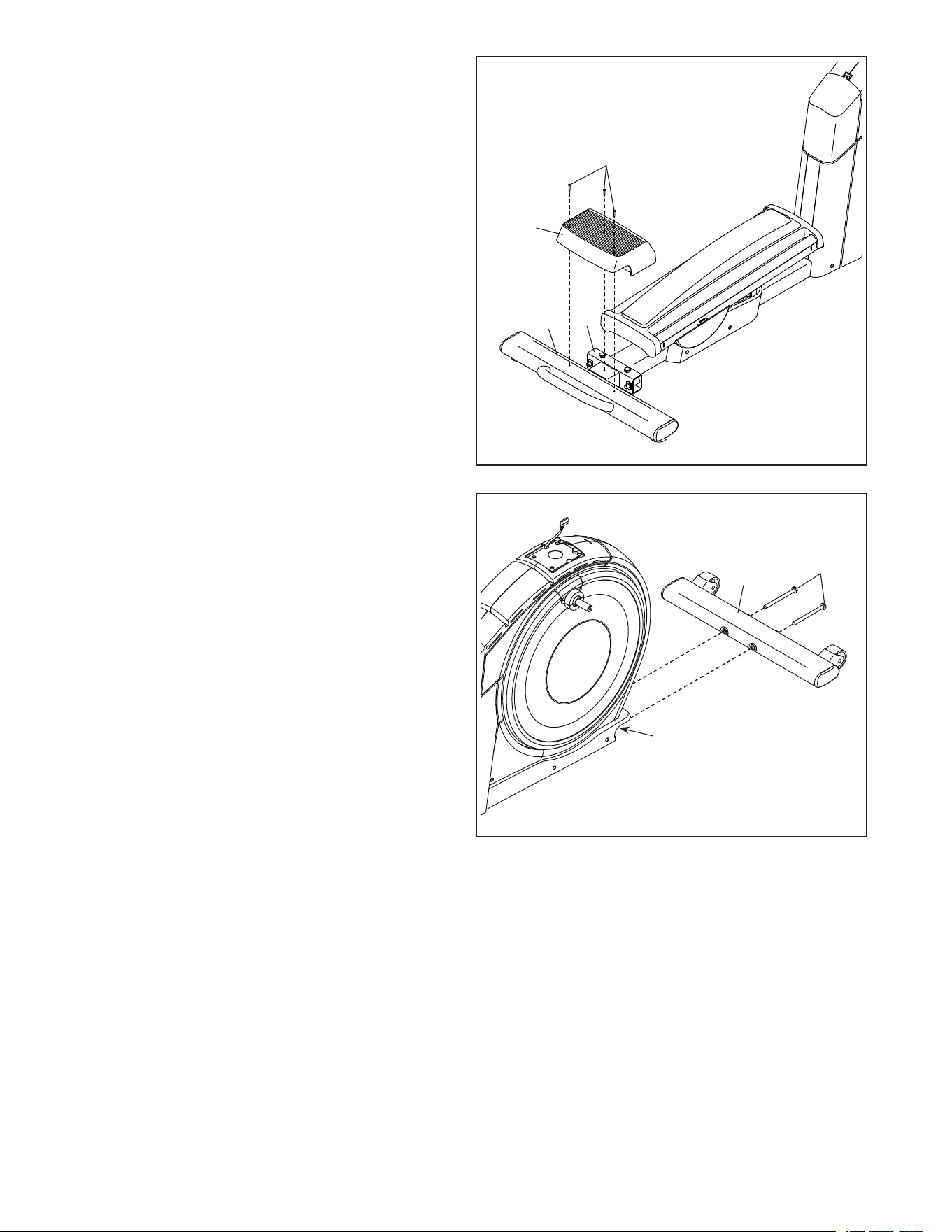
4
6
4. With the help of a second person, place some
of the packing materials (not shown) under the
front of the Frame (1). Have the second person
hold the Frame to prevent it from tipping until
you complete this step.
If there are shipping supports attached to the
front of the Frame (1), remove the screws from
the shipping supports, and discard the screws
and the shipping supports.
Next, attach the Front Stabilizer (6) to the Frame
(1) with two M10 x 115mm Screws (104).
Then, remove the packing materials from under
the Frame (1).
1
104
3. Attach the Rear Stabilizer Cover (15) to the Rear
Stabilizer (2) with three M4 x 18mm Machine
Screws (155); start all three Machine Screws,
and then tighten them.
3
1
2
155
15
9
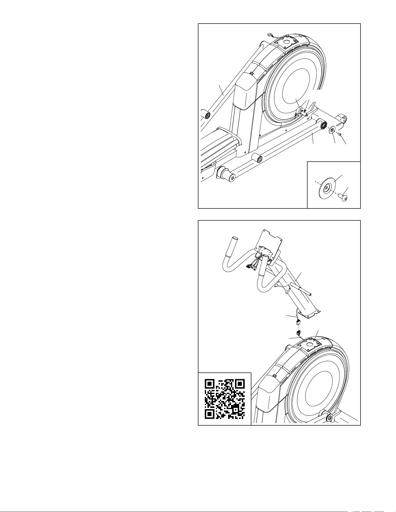
5
7759
45
95
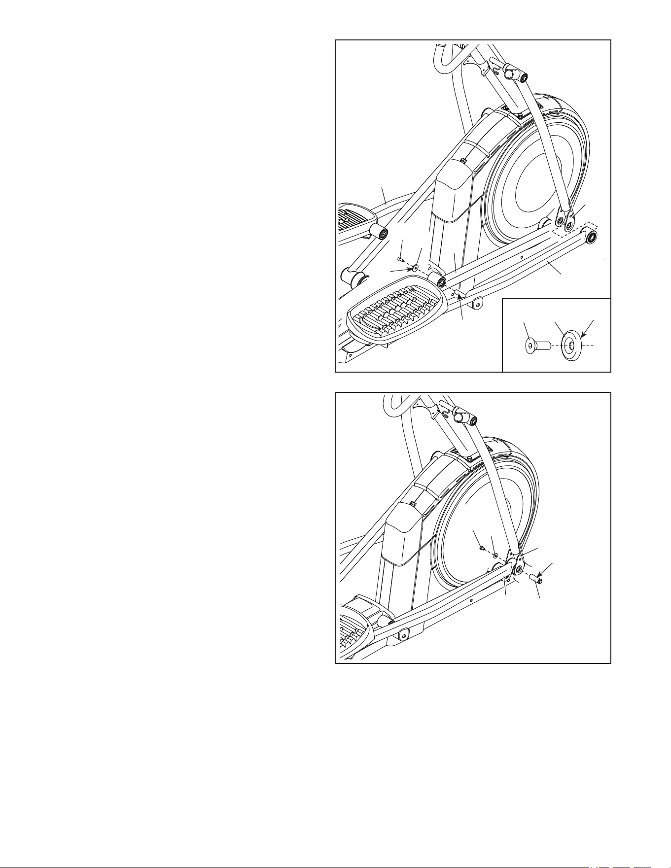
5. Apply a small amount of the included grease to
the axle on the right Crank Arm (20).
Next, identify the Right Roller Arm (59), orient
it as shown, and slide it onto the right Crank
Arm (20).
Attach the Right Roller Arm (59) with an
M8 x 20mm Screw (95) and a Crank Cover (77);
make sure that the Crank Cover is oriented
as shown in the inset drawing.
Repeat this step for the Left Roller Arm (45).
20
95
77
Grease
6
4
110
1
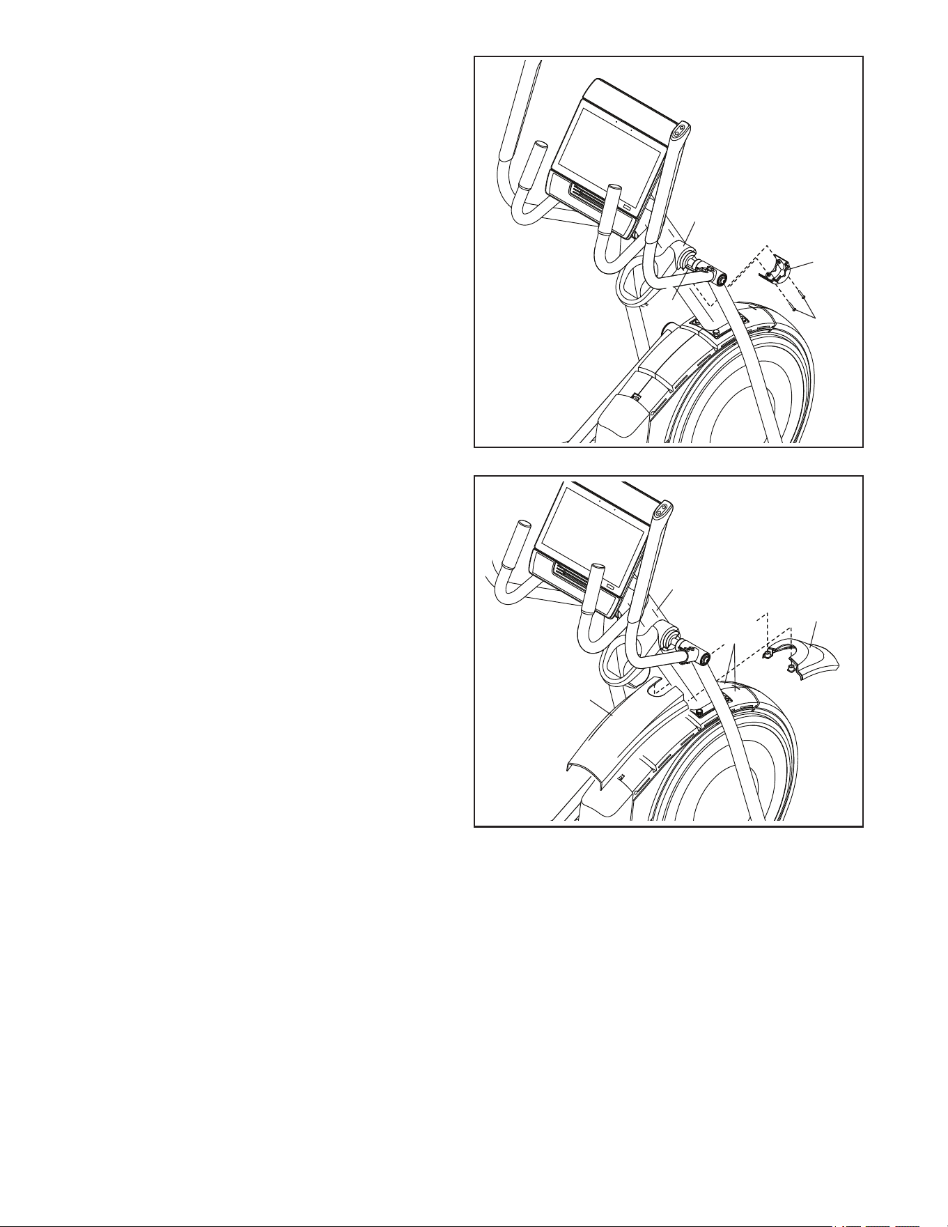
6. Have a second person hold the Upright (4) near
the Frame (1) as shown.
Next, connect the Upright Wire (157) to the Main
Wire (110).
IMPORTANT: The wire connectors should
slide together easily and snap into place
with an audible click. If they do not, turn one
connector and try again. You must connect
the wires properly for your elliptical to func-
tion properly. To see a short video about how
to connect wires, scan the QR code or go to
my.iFIT.com.
157
10
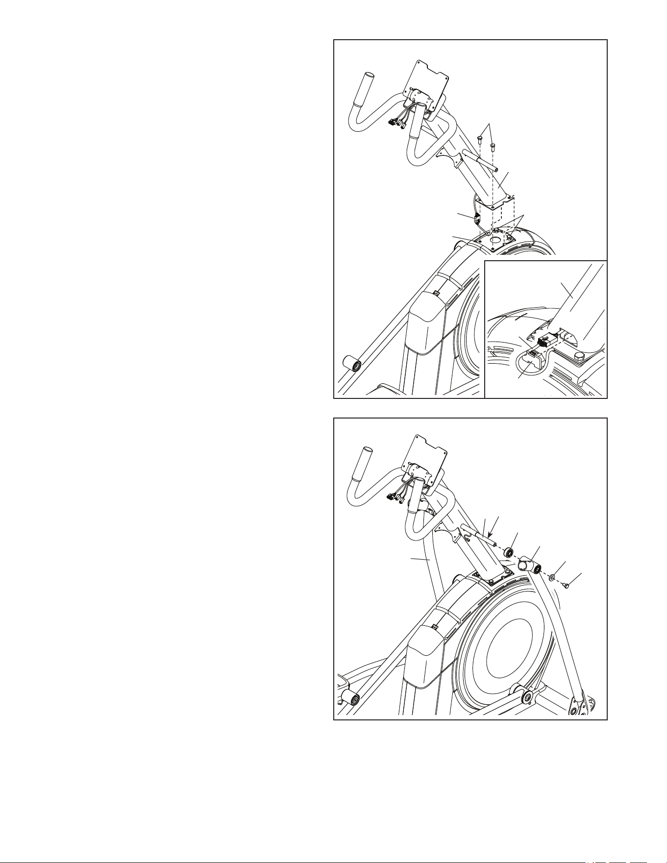
Avoid pinching
the wires
7
4
1
92
92
110
7. Avoid pinching the wires. Have a second
person hold the Upright (4) on the Frame (1).
Note: Two M10 x 25mm Screws (92) are
preattached to the Frame (1).
Attach the Upright (4) with two additional
M10 x 25mm Screws (92); do not fully tighten
the Screws yet.
See the inset drawing. Insert the connectors
on the wires into the left side of the Upright (4).
Next, route the Main Wire (110) through the
notch in the Grommet (156) as shown, and then
press the Grommet into the Upright.
4
156
110
8
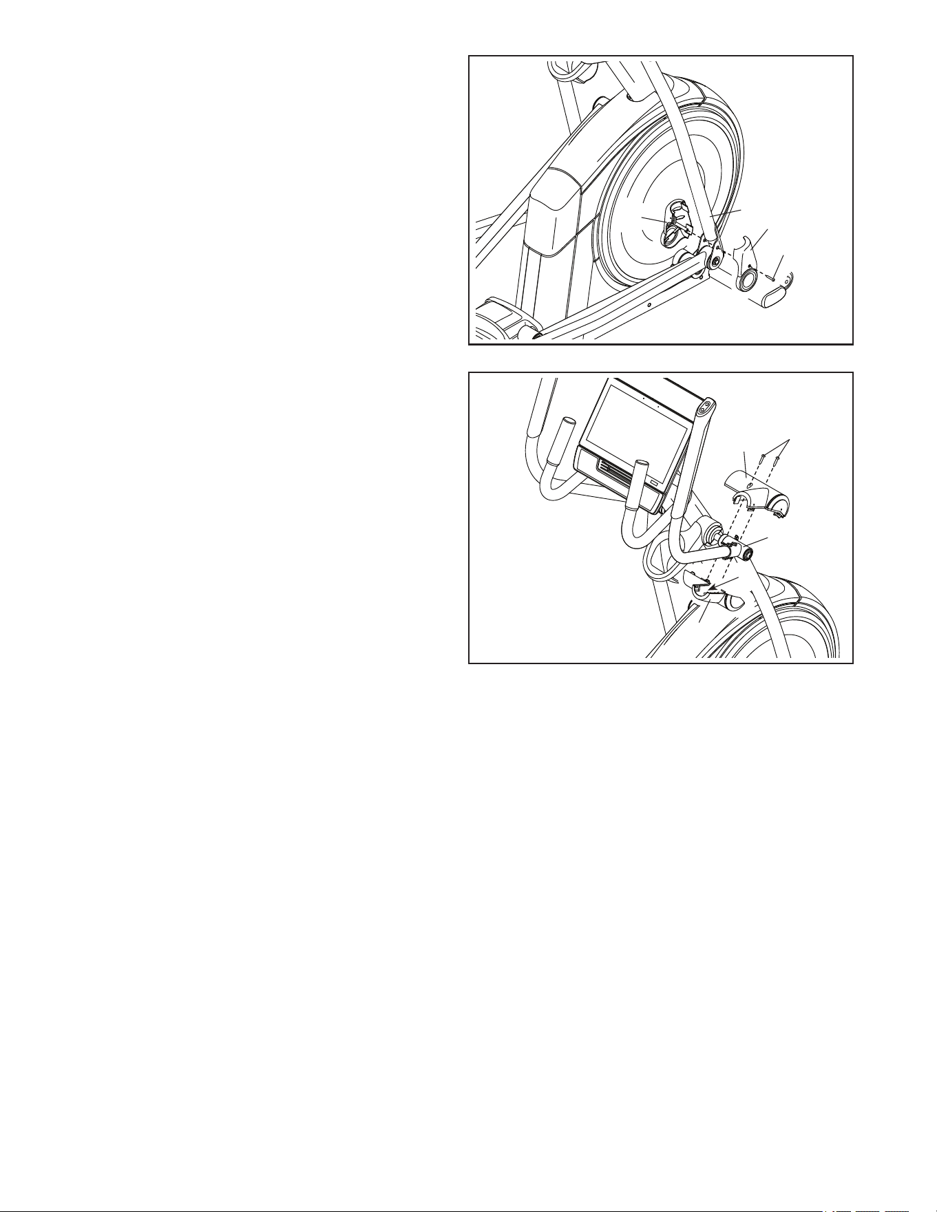
8. Apply grease to the axle on the right side of the
Upright (4).
Next, slide a Pivot Spacer (54) onto the right
side of the Upright (4).
Then, identify the Right Upper Body Leg (60),
orient it as shown, and slide it onto the right side
of the Upright (4).
Attach the Right Upper Body Leg (60) with an
M8 x 13mm Screw (82) and an M8 x 28mm
Washer (97).
Repeat this step to attach the Left Upper
Body Leg (46).
46
4
Grease
60
54
82
97
11
9
60
9. Orient the Right Pedal Arm (58) as shown, and
apply grease to the axle.
Insert the Right Pedal Arm (58) into the Right
Upper Body Leg (60) and into the Right Roller
Arm (59).
Attach the Right Pedal Arm (58) to the Right
Roller Arm (59) with an M8 x 20mm Flat Head
Screw (120) and a Retainer (55); make sure
that the flat side (A) of the Retainer is facing
the Right Roller Arm as shown in the inset
drawing.
Repeat this step for the Left Pedal Arm (44).
Grease
55
B
58
44
59
55
A
120
120
10
10. Apply grease to one of the Pedal Arm Axles (64).
Insert the Pedal Arm Axle (64) into the Right
Upper Body Leg (60) and the Right Pedal Arm
(58) from the direction shown.
Next, slide an M8 x 22mm Washer (129) onto an
M8 x 13mm Screw (82), and tighten the Screw a
few turns into the Pedal Arm Axle (64).
Then, tighten the Pedal Arm Axle (64) and the
M8 x 13mm Screw (82) at the same time.
Repeat this step on the other side of the
elliptical.
82
129
60
64
Grease
58
12
11
7
4
110
111,
146
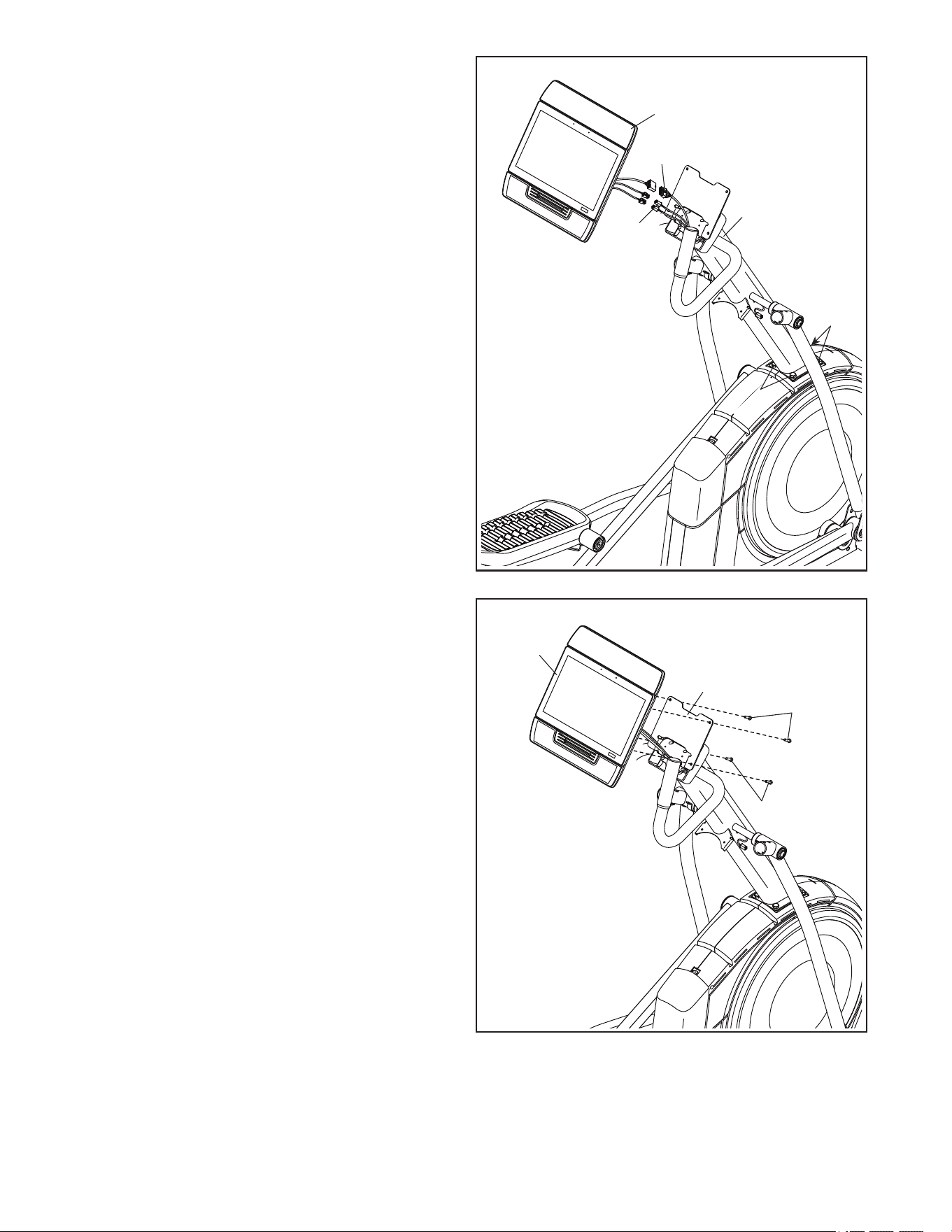
11. See step 7. Tighten the four M10 x 25mm
Screws (92).
Next, have a second person hold the Console
(7) near the Upright (4). Connect the wires on
the Console to the Main Wire (110) and to the
Left and Right Extension Wires (111, 146).
IMPORTANT: The wire connectors should
slide together easily and snap into place with
an audible click. If they do not, turn one con-
nector and try again. You must connect the
wires properly for your elliptical to function
properly.
Then, insert the connectors and the excess wire
into the Console (7).
92
92
12
Avoid pinching
the wires
7
101
128
12. If there is a hang tag (not shown) attached to the
Console Bracket (128), discard the hang tag.
Avoid pinching the wires. Attach the
Console (7) to the Console Bracket (128) with
four M4 x 16mm Screws (101); start all four
Screws, and then tighten them.
101
13
13
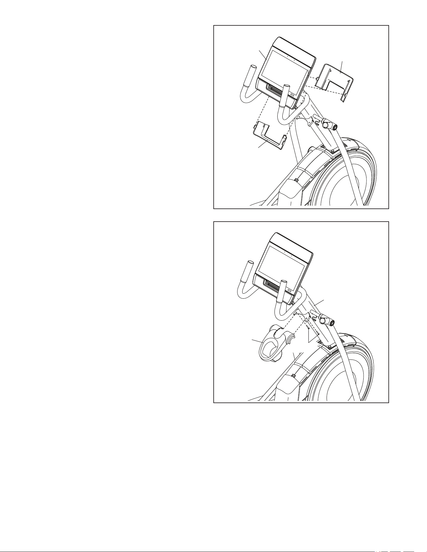
13. Orient the Lower Console Cover (152) as shown,
and snap it into the back of the Console (7).
Note: It may be helpful to pivot the Console
downward.
Then, orient the Upper Console Cover (153)
as shown, and snap it into the back of the
Console (7). Note: It may be helpful to pivot the
Console upward.
153
152
7
14
14. Orient the Accessory Tray (37) as shown, and
attach it to the Upright (4) with two M4 x 16mm
Screws (101).
4
101
37
14
15
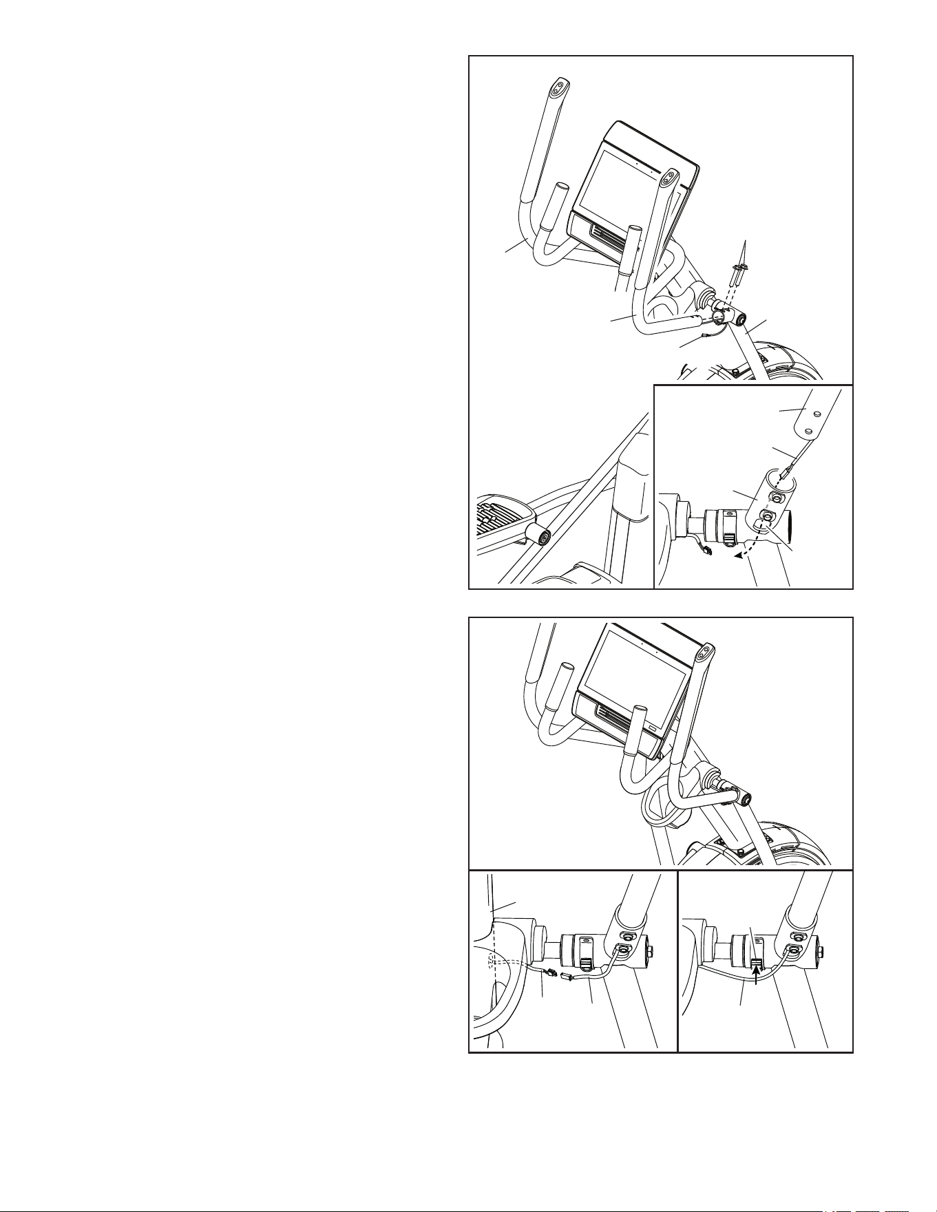
15. Identify the Right Upper Body Arm (61) and have
a second person hold it near the Right Upper
Body Leg (60).
See the inset drawing. Locate the Right Control
Wire (134) in the Right Upper Body Arm (61).
Feed the Right Control Wire into the Upper Body
Leg (60) and out of the indicated hole (D).
Avoid pinching the Right Control Wire (146).
Insert the Right Upper Body Arm (61) into
the Right Upper Body Leg (60). Attach the
Right Upper Body Arm with two M8 x 41mm
Screws (96).
Repeat this step with the Left Upper Body
Arm (47).
60
61
47
96
Avoid pinching
the wires
134
16
16. See the left inset drawing. Connect the Right
Control Wire (134) to the right Extension Wire
(111).
IMPORTANT: The wire connectors should
slide together easily and snap into place with
an audible click. If they do not, turn one con-
nector and try again. You must connect the
wires properly for your elliptical to function
properly.
Then, insert the connectors and the excess wire
into the Upright (4).
See the right inset drawing. Press the Right
Control Wire (134) into the slot in the Wire Clip
(159).
Repeat this step on the left side of the
elliptical.
111
134
134
4
159
134
60
61
D
15
17
101
81
37
17. Avoid pinching the wires. Orient a Lower Tray
Cover (81) as shown, and hold it near the Right
Control Wire (134). Attach the Lower Tray Cover
to the right side of the Accessory Tray (37) with
two M4 x 16mm Screws (101).
Repeat this step on the other side of the
elliptical.
Avoid
pinching
the wires
134
75
4
117
73, 74
18. Avoid pinching the wires. Press the Front
Shield Cover (117) onto the Left and Right
Shields (73, 74).
Then, press the Center Shield Cover (75) onto
the Left and Right Shields (73, 74).
Avoid pinching
the wires
18
16
21. Make sure that all parts are properly tightened. Extra parts may be included. Place a mat beneath the
elliptical to protect the floor. Note: Keep the included tools. One or more of the tools may be needed to make
adjustments in the future. To avoid damaging parts, do not use power tools for assembly or adjustment.
20
65
60
101
66
20. Avoid pinching the wires. Orient the Right Arm
Front and Rear Covers (65, 66) around the Right
Upper Body Leg (60) as shown, and attach them
with two M4 x 16mm Screws (101).
Repeat this step on the other side of the
elliptical.
Avoid pinching
the wires
E
19. Identify the Right Leg Inner Cover (83), orient it
as shown, and insert it through the Right Upper
Body Leg (60).
Next, identify the Right Leg Outer Cover (69),
orient it as shown, and press it onto the Right
Leg Inner Cover (83).
Attach the Right Leg Outer and Inner Covers
(69, 83) to each other with an M4 x 16mm
Screw (101).
Repeat this step on the other side of the
elliptical.
60
101
69
19
83
17
HOW TO USE THE ELLIPTICAL
HOW TO PLUG IN THE POWER CORD
This product must be earthed. If it should
malfunction or break down, earthing provides a path of
least resistance for electric current to reduce the risk
of electric shock. This product’s power cord has an
equipment-earthing conductor and an earthing plug.
IMPORTANT: If the power cord is damaged, it must
be replaced with a manufacturer-recommended
power cord.
Follow the steps below to plug in the power cord.
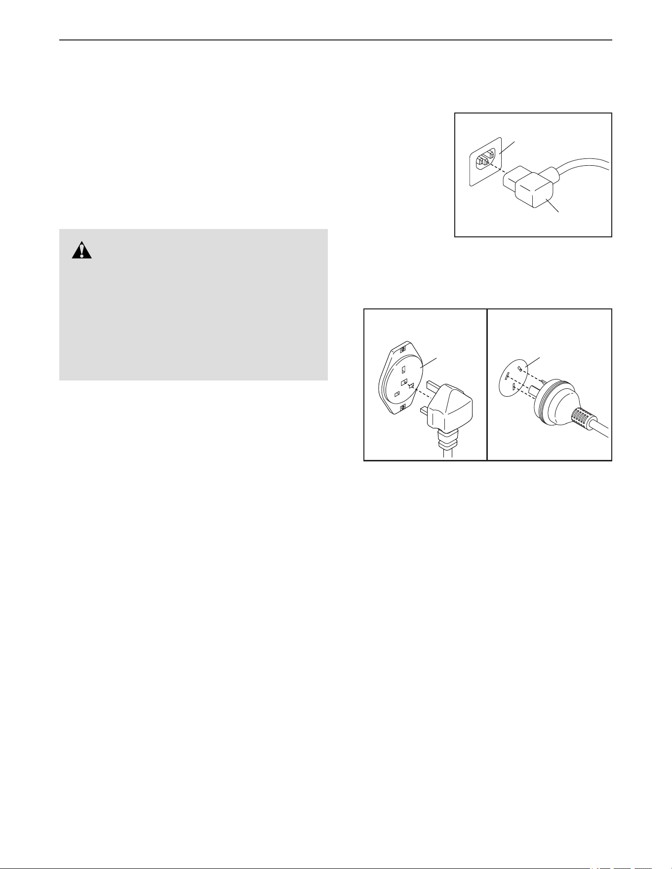
1. Plug the
indicated end
of the power
cord (A) into
the socket (B)
on the frame.
2. Plug the power cord into an appropriate outlet (C)
that is properly installed and earthed in accordance
with all local codes and ordinances.
DANGER: Improper connection of
the equipment-earthing conductor can result
in an increased risk of electric shock. Check
with a qualified electrician or serviceman if
you are in doubt as to whether the product
is properly earthed. Do not modify the plug
provided with the product—if it will not fit
the outlet, have a proper outlet installed by a
qualified electrician.
IT
FR/SP
UK
GR
RU
HU
AUS
B
A
IT
FR/SP
UK
GR
RU
HU
AUS
IT
FR/SP
UK
GR
RU
HU
AUS
C
UK
Australia
C
18
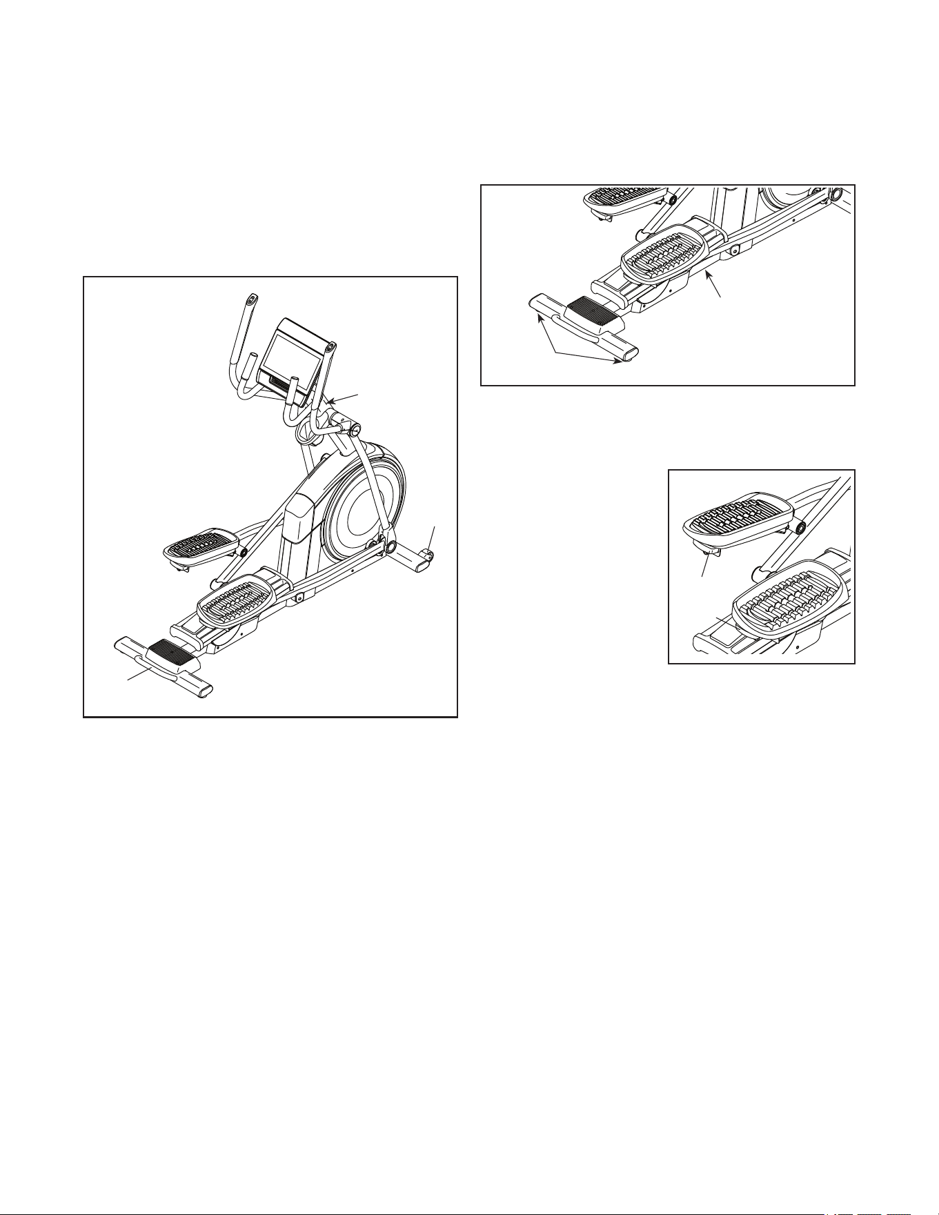
HOW TO MOVE THE ELLIPTICAL
Due to the size and weight of the elliptical, mov-
ing it requires two persons. Take any necessary
measures to avoid damaging your floor. Stand in
front of the elliptical, hold the upright (G), and place
one foot against one of the wheels (H). Next, pull on
the upright and have a second person lift the handle (I)
until the elliptical will roll on the wheels. Carefully move
the elliptical to the desired location, and then lower it to
the floor.
HOW TO LEVEL THE ELLIPTICAL
If the elliptical rocks slightly on your floor during use,
turn one or both of the leveling feet (J) beneath the rear
stabilizer or turn the leveling foot (K) under the center
of the frame until the rocking motion is eliminated.
HOW TO ADJUST THE POSITIONS OF THE
PEDALS
Each pedal can be
adjusted to several
positions. To adjust
each pedal, simply
pull the pedal handle
(L) outward, move the
pedal to the desired
position, and then
release the pedal
handle into an adjust-
ment hole beneath the
pedal. Make sure to
adjust both pedals to the same position.
G
I
H
J
K
L
L
19
HOW TO EXERCISE ON THE ELLIPTICAL
To mount the elliptical, hold the handlebars (M) or
the upper body arms (N) and step onto the pedal (O)
that is in the lower position. Then, step onto the other
pedal. Push the pedals until they begin to move with
a continuous motion. Note: The pedals can turn in
either direction. It is recommended that you turn
the pedals in the direction shown by the arrow;
however, for variety, you can turn the pedals in the
opposite direction.
To dismount the elliptical, wait until the pedals (O)
come to a complete stop. Note: The elliptical does
not have a free wheel; the pedals will continue to
move until the flywheel stops. When the pedals are
stationary, step off the higher pedal first. Then, step off
the lower pedal.
M
N
O
20
Rat
ELNT71420U
NTEL71420
HOW TO USE THE CONSOLE
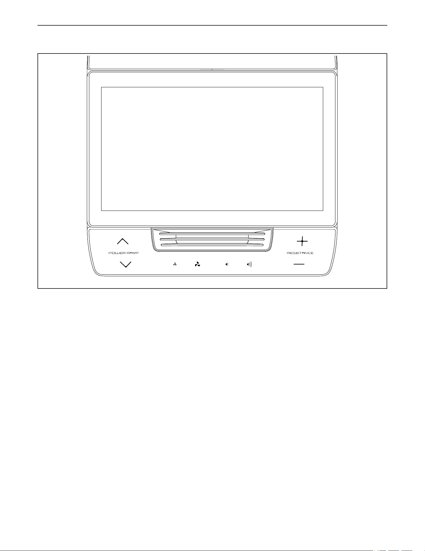
FEATURES OF THE CONSOLE
The advanced console offers an array of features
designed to make your workouts more effective and
enjoyable.
When you use the manual mode of the console, you
can change the resistance of the pedals and the incline
of the ramp with a touch of a button.
While you exercise, the console will display continuous
exercise feedback. You can even monitor your heart
rate using a compatible heart rate monitor. See page
31 for information about purchasing a compatible
heart rate monitor.
The console also features wireless technology that
enables the console to connect to iFIT
®
. With an iFIT
subscription, you can access a large and varied library
of thousands of destination and studio workouts, create
your own workouts, track your workout results, and
access many other features.
In addition, the console offers a rotating selection of
featured workouts. Each workout automatically con-
trols the resistance of the pedals and the incline of
the frame as an iFIT trainer guides you through an
effective exercise session.
To turn on and turn off the console, see page 21. To
learn how to use the touch screen, see page 21. To
set up the console, see page 22.

21
HOW TO TURN ON THE CONSOLE
IMPORTANT: If the elliptical has been exposed to
cold temperatures, allow it to warm to room tem-
perature before you turn on the console. If you do
not do this, you may damage the console or other
electrical components.
Plug in the power cord (see
HOW TO PLUG IN THE POWER
CORD on page 17). Next, locate
the power switch on the frame
near the power cord. Press the
power switch to the reset posi-
tion (A).
The console will then turn on and be ready for use.
Note: When you turn on the console for the rst
time, the incline system may calibrate automati-
cally. The ramp will move upward and downward as
it calibrates. When the ramp stops moving, the incline
system is calibrated.
IMPORTANT: If the incline system does not
calibrate automatically, see step 7 on page 29 and
manually calibrate the incline system.
HOW TO TURN OFF THE CONSOLE
When you are finished exercising, press the power
switch to the off position and unplug the power cord.
IMPORTANT: If you do not do this, the electrical
components of the elliptical may wear prematurely.
HOW TO USE THE TOUCH SCREEN
The console features a tablet with a full-color touch
screen. The following information will help you use the
touch screen:
• The console functions similarly to other tablets. You
can slide or flick your finger against the screen to
move certain images on the screen, such as the
displays in a workout.
• To type information into a text box, first touch the text
box to view the keyboard. To use numbers or other
characters on the keyboard, touch ?123. To view
more characters, touch ~[<. Touch ?123 again to
return to the number keyboard. To return to the letter
keyboard, touch ABC. To use a capital character,
touch the shift button (upward-facing arrow symbol).
To use multiple capital characters, touch the shift
button again. To return to the lowercase keyboard,
touch the shift button a third time. To clear the last
character, touch the clear button (backward-facing
arrow with an X symbol).
A

22
HOW TO SET UP THE CONSOLE
Before you use the elliptical for the first time, set up the
console.
1. Connect to your wireless network.
To use iFIT workouts and to use several other
features of the console, the console must be con-
nected to a wireless network. Follow the prompts
on the screen to connect the console to your wire-
less network.
2. Customize settings.
Follow the prompts on the screen to set the desired
unit of measurement and your time zone.
Note: To change these settings later, see HOW TO
CHANGE CONSOLE SETTINGS on page 28.
3. Log into or create an iFIT account.
Follow the prompts on the screen to log into your
iFIT account or to create an iFIT account.
4. Check for firmware updates.
Touch the menu button (three horizontal lines
symbol), touch Settings, touch Maintenance, and
then touch Update. The console will check for firm-
ware updates. For more information, see HOW TO
CHANGE CONSOLE SETTINGS on page 28.
Firmware updates are always designed to
improve your exercise experience. As a result,
new settings and features may not be described
in this manual. Also, some settings and fea-
tures described in this manual may no longer be
enabled. Take time to explore the console to learn
how new settings and features work.
5. Calibrate the incline system.
Touch the menu button (three horizontal lines
symbol), touch Settings, touch Maintenance, and
then touch Calibrate Incline. The ramp will rise
and lower as it calibrates. For more information,
see HOW TO CHANGE CONSOLE SETTINGS on
page 28.
The console is now ready for you to begin working out.
The following pages explain the workouts and other
features that the console offers.
To use the manual mode, see page 23. To use a
featured workout, see page 24. To create a draw-
your-own-map workout, see page 26. To use an iFIT
workout, see page 27.
To change console settings, see page 28. To
connect to a wireless network, see page 30.
Note: If there is a sheet of plastic on the screen,
remove the plastic.

23
HOW TO USE THE MANUAL MODE
1. Touch the screen or press any button on the
console to turn on the console.
See HOW TO TURN ON THE CONSOLE on page
21. Note: It may take up to a few minutes for the
console to be ready for use.
2. Select the home screen.
When you turn on the console, the home screen
will appear after the console boots up.
If a workout is selected, touch the screen and
follow the prompts to end the workout and return
to the home screen. If a settings menu is selected,
touch the back button (arrow symbol) to return to
the home screen.
3. Get ready for the workout.
Touch Manual Start and begin pedaling. A warm-up
period will begin.
To use the fan, see page 31.
To use a heart rate monitor, see page 31.
4. Change the resistance of the pedals and the
incline of the ramp as desired.
Touch End Warmup or pedal until the warm-up
period ends to start the workout.
You can change the resistance of the pedals in the
following ways:
• Press the Resistance increase and decrease
buttons on the console.
• Press the Resistance increase and decrease
buttons on the right handlebar.
• Touch the resistance sliders on the screen.
You can vary the motion of the pedals in the
following ways.
• Press the Ramp increase and decrease buttons
on the console.
• Press the Ramp increase and decrease buttons
on the left handlebar.
• Touch the incline sliders on the screen.
Note: After you press a button, it will take a
moment for the pedals to reach the selected resis-
tance level or for the ramp to reach the selected
incline level.
Note: To view the resistance or incline sliders on
the screen, touch the screen in any open space
and then touch the controls options to enable this
feature.
5. Follow your progress.
The console offers several display modes. The
display mode that you select will determine which
workout information is shown.
Drag upward on the screen to enter the fullscreen
display mode. Drag downward on the screen to
view the workout information displays.
Touch the various workout information displays
to view more options. Touch the more button
(
+
symbol) to view statistics or charts. Touch the
screen in any open space to view even more dis-
play mode options.
If desired, adjust the vol-
ume level by pressing the
Vol increase and decrease
buttons.
6. Pause or end the workout.
To pause the workout, touch the screen and touch
the pause option or simply stop pedaling. To con-
tinue the workout, touch the start option or simply
resume pedaling.
To end the workout session, touch the screen,
touch the pause option, and then follow the
prompts on the screen to end the workout and
return to the home screen.
7. When you are finished exercising, turn off the
console.
See HOW TO TURN OFF THE CONSOLE on
page 21.

24
HOW TO USE A FEATURED WORKOUT
To use a featured workout, the console must be con-
nected to a wireless network (see HOW TO CONNECT
TO A WIRELESS NETWORK on page 30).
1. Touch the screen or press any button on the
console to turn on the console.
See HOW TO TURN ON THE CONSOLE on page
21. Note: It may take up to a few minutes for the
console to be ready for use.
2. Select the home screen or the workout library.
When you turn on the console, the home screen
will appear after the console boots up.
If a workout is selected, touch the screen and
follow the prompts to end the workout and return
to the home screen. If a settings menu is selected,
touch the back button (arrow symbol) to return to
the home screen.
Touch the buttons at the bottom of the screen to
select either the home screen (Home button) or the
workout library (Browse button).
3. Select a workout.
To select a workout from the home screen or the
workout library, simply touch the desired workout
button on the screen. Slide or flick the screen to
scroll as necessary.
The featured workouts on your console will change
periodically. To save one of the featured workouts
for future use, you can add it as a favorite by touch-
ing the favorites button (heart symbol). You must
be logged into your iFIT account to save a featured
workout (see step 3 on page 27).
To draw your own map for a workout, see HOW TO
CREATE A DRAW-YOUR-OWN-MAP WORKOUT
on page 26.
When you select a workout, the screen will show
an overview of the workout that includes details
such as the duration and distance of the workout
and the approximate number of calories you will
burn during the workout.
4. Get ready for the workout.
Touch Start Workout and begin pedaling. A
warm-up period will begin.
To use the fan, see page 31.
To use Bluetooth headphones, see page 31.
To use a heart rate monitor, see page 31.
5. Start the workout.
Touch End Warmup or pedal until the warm-up
period ends to start the workout.
During some workouts, an iFIT trainer will guide
you through an immersive video workout. Touch
the screen in any open space to view and select
music, trainer voice, and volume options for the
workout.
During some workouts, the screen will show a map
of the route and a marker indicating your prog-
ress. Touch the buttons on the screen to select the
desired map options.
During some workouts, you may be prompted to
maintain a target speed. As you exercise, keep
your pedaling speed near the target speed.
IMPORTANT: The target speed is intended only
to provide motivation. Your actual pedaling
speed may be slower than the target speed.
Make sure to pedal at a speed that is comfort-
able for you.
If the resistance level is too high or too low, you
can manually override the setting by pressing the
Resistance buttons or the Ramp buttons (see step
4 on page 23).
To return to the programmed resistance settings of
the workout, touch Follow Workout.

25
If the smart adjust feature is enabled, the console
will scale the intensity level of the workout auto-
matically based on your manual overrides of the
resistance settings.
To enable the smart adjust feature, touch the
screen in any open space and then touch the smart
adjust toggle.
IMPORTANT: The calorie goal shown in the
workout description is an estimate of the
number of calories that you will burn during
the workout. The actual number of calories
that you burn will depend on various factors,
such as your weight. In addition, if you manu-
ally change the resistance level or incline level
of the ramp during the workout, the number of
calories you burn will be affected.
If the active pulse feature is enabled, the console
will scale the intensity level of the workout auto-
matically based on your heart rate when you wear
a compatible heart rate monitor (see HOW TO
USE AN OPTIONAL HEART RATE MONITOR on
page 31).
To enable the active pulse feature, see HOW TO
CHANGE CONSOLE SETTINGS on page 28.
To follow your progress with the display
modes, see step 5 on page 23.
To pause or end the workout, see step 6 on
page 23.
6. When you are finished exercising, turn off the
console.
See HOW TO TURN OFF THE CONSOLE on
page 21.

26
HOW TO CREATE A DRAW-YOUR-OWN-MAP
WORKOUT
To use a draw-your-own-map workout, you must be
logged into your iFIT account (see step 3 on page
27) and the console must be connected to a wireless
network (see HOW TO CONNECT TO A WIRELESS
NETWORK on page 30).
1. Touch the screen or press any button on the
console to turn on the console.
See HOW TO TURN ON THE CONSOLE on page
21. Note: It may take up to a few minutes for the
console to be ready for use.
2. Select a draw-your-own-map workout.
When you turn on the console, the home screen
will appear after the console boots up.
If a workout is selected, touch the screen and fol-
low the prompts to end the workout and return to
the home screen. If a settings menu is selected,
touch the back button (arrow symbol) to return to
the home screen.
To select a draw-your-own-map workout, touch the
Create button at the bottom of the screen.
3. Draw a workout on the map.
Navigate to the area on the map where you want
to draw a workout by typing in the search box
or by sliding your fingers on the screen. Touch
the screen to add the start point for the workout.
Then, touch the screen to add the end point for the
workout.
If you want to start and end the workout at the
same point, touch Close Loop or Out & Back in the
map options. You can also select whether you want
the workout to snap to the road.
If you make a mistake, touch Undo in the map
options.
The screen will display the elevation and distance
statistics for the workout.
4. Save the workout.
Touch the options on the screen to save the
workout. If desired, enter a title and description for
the workout.
5. Get ready for the workout.
Touch Start Workout and begin pedaling. A
warm-up period will begin.
To use the fan, see page 31.
To use Bluetooth headphones, see page 31.
To use a heart rate monitor, see page 31.
6. Start the workout.
Touch End Warmup or pedal until the warm-up
period ends to start the workout. The workout will
function in the same way as a featured workout
(see step 5 on page 24).
7. When you are finished exercising, turn off the
console.
See HOW TO TURN OFF THE CONSOLE on
page 21.

27
HOW TO USE AN IFIT WORKOUT
To use an iFIT workout, you must be logged into your
iFIT account (see step 3 below) and the console must
be connected to a wireless network (see HOW TO
CONNECT TO A WIRELESS NETWORK on page 30).
1. Touch the screen or press any button on the
console to turn on the console.
See HOW TO TURN ON THE CONSOLE on
page 22. Note: It may take up to a few minutes
for the console to be ready for use.
2. Select the home screen.
When you turn on the console, the home screen
will appear after the console boots up.
If a workout is selected, touch the screen and
follow the prompts to end the workout and return
to the home screen. If a settings menu is selected,
touch the back button (arrow symbol) to return to
the home screen.
3. Log in to your iFIT account.
If you have not already done so, touch the menu
button (three horizontal lines symbol) on the screen
and then touch Log in to log in to your iFIT account.
Follow the prompts on the screen to enter your
username and password.
To switch users within your iFIT account, touch
the menu button, touch Settings, and then touch
Manage Accounts. If more than one user is associ-
ated with the account, a list of users will appear.
Touch the name of the desired user.
4. Select an iFIT workout from the home screen or
the workout library.
Touch the buttons at the bottom of the screen to
select either the home screen (Home button) or the
workout library (Browse button).
To select an iFIT workout from the home screen or
the workout library, simply touch the desired work-
out button on the screen. Slide or flick the screen to
scroll as necessary.
The featured iFIT workouts shown on the home
screen will change periodically.
The workout library contains all of the iFIT work-
outs available for the elliptical, organized into
categories. To search the workout library, touch
the search button (magnifying glass symbol), and
select the desired filtering options.
When you select an iFIT workout, the screen will
show an overview of the workout that includes
details such as the duration of the workout and the
approximate number of calories you will burn dur-
ing the workout.
You can also select options such as adding the
workout to your schedule (see step 5) or marking
the workout as a favorite (see step 6).
5. Schedule an iFIT workout on the calendar if
desired.
If desired, you can schedule an iFIT workout for
a future date. Simply view the overview or work-
out summary of the desired iFIT workout, touch
Schedule, and then select the desired date on the
calendar.
When the selected date arrives, the iFIT workout
that you scheduled will appear on the home
screen.
6. Create a list of favorite iFIT workouts if desired.
To mark an iFIT workout as a favorite, simply view
the overview or workout summary of the desired
iFIT workout and touch the favorites button (heart
symbol).
To view a list of iFIT workouts that you have
marked as your favorites, select the workout library
(Browse button), and then touch My List.

28
7. Get ready for the workout.
Touch Start Workout and begin pedaling. A
warm-up period will begin.
To use the fan, see page 31.
To use Bluetooth headphones, see page 31.
To use a heart rate monitor, see page 31.
8. Start the workout.
Touch End Warmup or pedal until the warm-up
period ends to start the workout. The workout will
function in the same way as a featured workout
(see step 5 on page 24).
9. When you are finished exercising, turn off the
console.
See HOW TO TURN OFF THE CONSOLE on
page 21.
For more information about iFIT, go to iFIT.com.
HOW TO CHANGE CONSOLE SETTINGS
IMPORTANT: Firmware updates (see step 6) are
always designed to improve your exercise experi-
ence. As a result, new settings and features may not
be described in this manual. Also, some settings and
features described in this manual may no longer be
enabled. Take time to explore the console to learn how
new settings and features work.
1. Select the settings main menu.
First, turn on the console (see HOW TO TURN ON
THE CONSOLE on page 21). Note: It may take
up to a few minutes for the console to be ready
for use.
Next, select the home screen (Home button). When
you turn on the console, the home screen will
appear after the console boots up. If a workout is
selected, touch the screen and follow the prompts
to end the workout and return to the home screen.
If a settings menu is selected, touch the back but-
ton (arrow symbol) to return to the home screen.
Then, touch the menu button (three horizontal lines
symbol) on the screen, and then touch Settings.
The settings menu will appear on the screen.
2. Navigate the settings menus and change
settings as desired.
Slide or flick the screen to scroll as necessary.
To view a settings menu, simply touch the menu
name. To exit a menu, touch the back button (arrow
symbol). You may be able to view and change set-
tings in the following settings menus:
Account
• My Prole
• In Workout
• Manage Accounts
Equipment
• Equipment Info
• Equipment Settings
• Maintenance
• Wi-Fi
About
• Legal

29
3. Customize workout settings.
To customize workout settings and enable work-
out features, touch In Workout and then touch the
desired settings.
When the active pulse feature is enabled, the
console will scale the intensity level of workouts
based on your heart rate when you wear a compat-
ible heart rate monitor. To enable the active pulse
feature, touch the active pulse toggle. Then, select
your resting and maximum heart rates and adjust
related settings as desired.
4. Customize the unit of measurement and other
settings.
To customize the unit of measurement, the time
zone, or other settings, touch Equipment Info or
Equipment Settings and then touch the desired
settings.
The console can display speed and distance in
either standard or metric units of measurement.
5. View machine information or console app
information.
Touch Equipment Info and then touch Machine Info
or App Info to view information about your elliptical
or about the console app.
6. Update the console firmware.
For the best results, regularly check for firm-
ware updates. Touch Maintenance and then touch
Update to check for firmware updates using your
wireless network. The update will begin auto-
matically. IMPORTANT: To avoid damaging the
elliptical, do not turn off the console while the
firmware is being updated.
The screen will show the progress of the update.
When the update is complete, the console will turn
off and then turn back on. If it does not, press the
power switch into the off position. Wait for several
seconds, and then press the power switch into the
reset position. Note: It may take up to a few min-
utes for the console to be ready for use.
Note: Occasionally, a firmware update may cause
the console to function slightly differently. These
updates are always designed to improve your
exercise experience.
7. Calibrate the incline system.
To calibrate the incline system, touch Maintenance,
touch Calibrate Incline, and then touch Begin. The
ramp will automatically rise to the maximum incline
level, lower to the minimum incline level, and then
return to the starting position. This will calibrate
the incline system. When the incline system is
calibrated, touch Finish.
IMPORTANT: Keep pets, feet, and other objects
away from the elliptical while the incline system
is calibrating.
8. Exit the settings main menu.
To exit the settings main menu, touch the back
button (arrow symbol).

30
HOW TO CONNECT TO A WIRELESS NETWORK
To use iFIT workouts and to use several other features
of the console, the console must be connected to a
wireless network.
1. Select the home screen.
First, turn on the console (see HOW TO TURN ON
THE CONSOLE on page 21). Note: It may take
up to a few minutes for the console to be ready
for use.
Next, select the home screen (Home button). When
you turn on the console, the home screen will
appear after the console boots up. If a workout is
selected, touch the screen and follow the prompts
to end the workout and return to the home screen.
If a settings menu is selected, touch the back but-
ton (arrow symbol) to return to the home screen.
2. Select the wireless network menu.
Touch the menu button (three horizontal lines
symbol), and then touch Wi-Fi to select the
wireless network menu.
3. Enable Wi-Fi
®
.
Make sure that Wi-Fi is enabled. If it is not enabled,
touch the Wi-Fi toggle to enable it.
4. Set up and manage a wireless network
connection.
When Wi-Fi is enabled, the screen will show a
list of available networks. Note: It may take a few
moments for the list of wireless networks to appear.
Note: You must have your own wireless network
and an 802.11b/g/n router with SSID broadcast
enabled (hidden networks are not supported).
When a list of networks appears, touch the desired
network. Note: You will need to know your network
name (SSID). If your network has a password, you
will also need to know the password.
Follow the prompts on the screen to enter your
password and connect to the selected wireless
network. (To use the keyboard, see HOW TO USE
THE TOUCH SCREEN on page 21.)
When the console is connected to your wireless
network, a confirmation message will appear on the
screen.
If you are having problems connecting to an
encrypted network, make sure that your password
is correct. Note: Passwords are case-sensitive.
Note: The console supports unsecured and
secured (WEP, WPA™, and WPA2™) encryption.
A broadband connection is recommended; perfor-
mance depends on connection speed.
Note: If you have questions after follow-
ing these instructions, go to my.iFIT.com for
assistance.
5. Exit the wireless network menu.
To exit the wireless network menu, touch the back
button (arrow symbol).

31
HOW TO USE THE FAN
The fan has several speed
settings, including an auto
mode. While the auto mode
is selected, the speed of the
fan will automatically increase
or decrease as your pedaling speed increases or
decreases. Press the Fan increase and decrease but-
tons on the console repeatedly to select a fan speed or
to turn off the fan.
HOW TO CONNECT HEADPHONES
To connect your Bluetooth headphones to the console,
first turn on your headphones, place them in pairing
mode, and place them near the console. Then, start
a workout. Next, touch the screen in any open space,
touch the option to connect your headphones, and
select your headphones from the list on the screen.
When your headphones and the console pair
successfully, the audio from the console will play
through your headphones.
HOW TO USE AN OPTIONAL HEART RATE
MONITOR
Whether your
goal is to
burn fat or to
strengthen your
cardiovascular
system, the key
to achieving the
best results is
to maintain the
proper heart
rate during your
workouts. The optional heart rate monitor will enable
you to continuously monitor your heart rate while you
exercise, helping you to reach your personal fitness
goals. To purchase an optional heart rate monitor,
please see the front cover of this manual.
The console is compatible with all Bluetooth
®
Smart
heart rate monitors.
When your compatible heart rate monitor is turned on
and placed in pairing mode, the console will connect to
it automatically. When your heartbeat is detected, your
heart rate will be shown on the screen.
32
MAINTENANCE
Regular maintenance is important for optimal
performance and to reduce wear. Inspect and properly
tighten all parts each time the elliptical is used.
Replace any worn parts immediately. Use only
manufacturer-supplied parts.
To clean the elliptical, use a damp cloth and a small
amount of mild soap. IMPORTANT: To avoid damage
to the console, keep liquids away from the console
and keep the console out of direct sunlight.
TROUBLESHOOTING
Many problems can be solved with the simple
steps in this section. Find the symptom that
applies, and follow the steps listed. If further assis-
tance is needed, see the front cover of this manual.
INCLINE SYSTEM TROUBLESHOOTING
If the ramp does not move to the correct incline level,
see step HOW TO CHANGE CONSOLE SETTINGS
on page 28 and calibrate the incline system.
CONSOLE TROUBLESHOOTING
If the console does not turn on, make sure that the
power cord is fully plugged in and that the power
switch is in the reset position. If there are exterior wires
on the console, make sure that the connectors on the
wires are oriented correctly and are connected firmly.
If you are having problems connecting the console to
a wireless network or if you are having problems with
your iFIT account or iFIT workouts, go to my.iFIT.com.
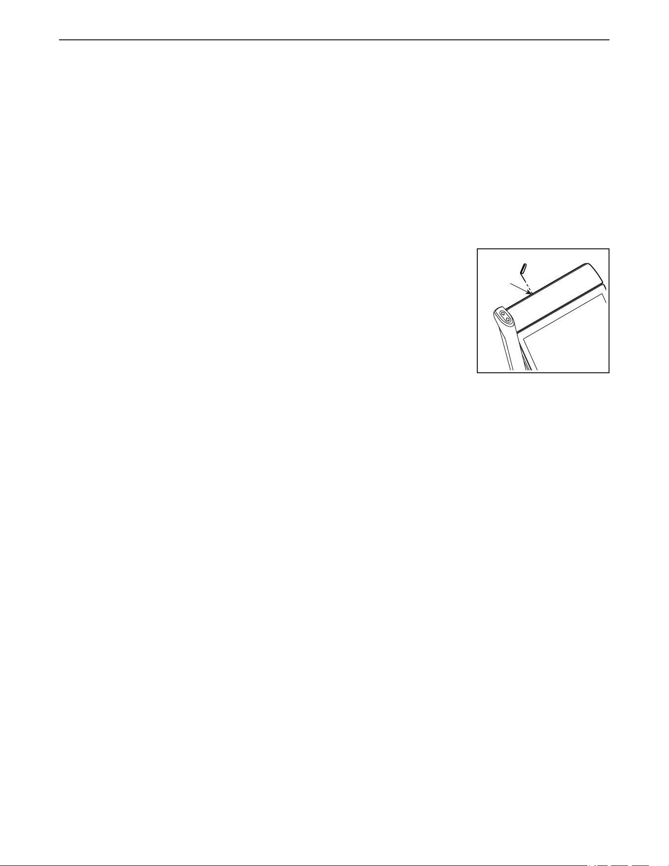
If the console does not
boot up properly, or if
the console freezes
and does not respond,
reset the console to the
factory default settings.
IMPORTANT: Doing
this will erase all cus-
tom settings you have
made to the console.
Resetting the console
requires two people. First, press the power switch and
unplug the power cord. Next, locate the small reset
opening (A) on the top of the console. Using a bent
paper clip, press and hold the reset button inside of the
opening, and have a second person plug in the power
cord and press the power switch. Continue holding the
reset button until the console turns on. When the reset
operation is complete, the console will turn off and then
turn back on. If it does not, press the power switch
off and then on again. Once the console turns on,
check for rmware updates (see HOW TO CHANGE
CONSOLE SETTINGS page 28). Note: It may take
up to a few minutes for the console to be ready for
use.
A
MAINTENANCE AND TROUBLESHOOTING
33
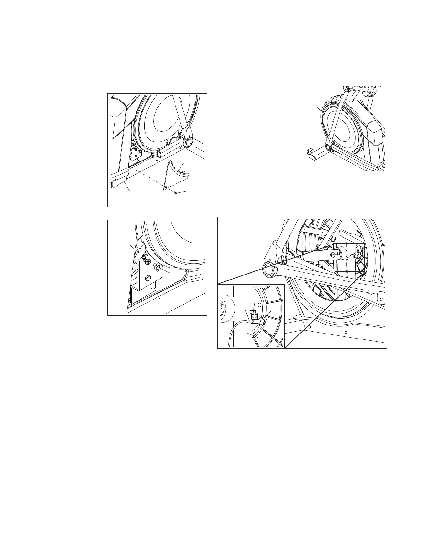
HOW TO ADJUST THE DRIVE BELT
If the pedals slip while you are pedaling, even while
the resistance is adjusted to the highest level, the drive
belt may need to be adjusted. To adjust the drive belt,
first press the power switch to the off position and
unplug the power cord.
Next, locate the
Access Cover
(3) on the Right
Shield (74).
Remove the
M4 x 16mm
Screw (101), and
then remove the
Access Cover.
Next, locate
and loosen the
Idler Screw (89).
Tighten the Drive
Belt Adjustment
Screw (91) until
the Drive Belt
(113) is tight. Then,
retighten the Idler
Screw.
Reattach the parts that you removed. Then, plug in the
power cord and press the power switch.
HOW TO ADJUST THE REED SWITCH
If the console does not display correct feedback,
the reed switch should be adjusted. To adjust the
reed switch, first press the power switch to the off
position and unplug the power cord.
Next, using a stan-
dard screwdriver,
carefully pry off the
left Disc (71).
See the drawing below. Locate the Reed Switch (38).
Turn the Pulley (19) until a Magnet (43) is aligned with
the Reed Switch.
Next, slightly loosen the indicated two M4 x 12mm
Self-tapping Screws (50). Slide the Reed Switch (38)
slightly closer to or away from the Magnet (43), and
then retighten the Self-tapping Screws.
Then, plug in the power cord, press the power switch,
and rock the Pulley (19) forward and backward just
enough that the Magnet (43) passes the Reed Switch
(38) repeatedly. Repeat these actions until the console
displays correct feedback.
When the reed switch is correctly adjusted, reattach
the left disc, plug in the power cord, and press the
power switch.
74
3
101
91
89
113
19
43
50
38
71
34
EXERCISE GUIDELINES
These guidelines will help you to plan your exercise
program. For detailed exercise information, obtain a
reputable book or consult your physician. Remember,
proper nutrition and adequate rest are essential for
successful results.
EXERCISE INTENSITY
Whether your goal is to burn fat or to strengthen your
cardiovascular system, exercising at the proper inten-
sity is the key to achieving results. You can use your
heart rate as a guide to find the proper intensity level.
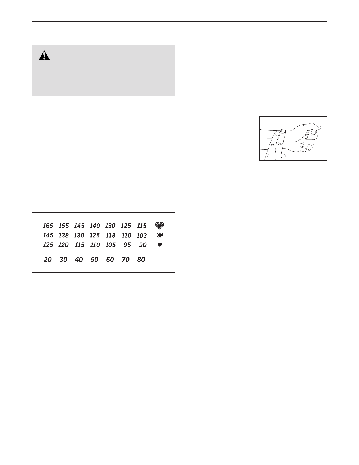
The chart below shows recommended heart rates for
fat burning and aerobic exercise.
To find the proper intensity level, find your age at the
bottom of the chart (ages are rounded off to the near-
est ten years). The three numbers listed above your
age define your “training zone.” The lowest number is
the heart rate for fat burning, the middle number is the
heart rate for maximum fat burning, and the highest
number is the heart rate for aerobic exercise.
Burning Fat—To burn fat effectively, you must exer-
cise at a low intensity level for a sustained period of
time. During the first few minutes of exercise, your
body uses carbohydrate calories for energy. Only
after the first few minutes of exercise does your body
begin to use stored fat calories for energy. If your
goal is to burn fat, adjust the intensity of your exer-
cise until your heart rate is near the lowest number in
your training zone. For maximum fat burning, exercise
with your heart rate near the middle number in your
training zone.
Aerobic Exercise—If your goal is to strengthen your
cardiovascular system, you must perform aerobic
exercise, which is activity that requires large amounts
of oxygen for prolonged periods of time. For aerobic
exercise, adjust the intensity of your exercise until
your heart rate is near the highest number in your
training zone.
HOW TO MEASURE YOUR HEART RATE
To measure your heart
rate, exercise for at least
four minutes. Then, stop
exercising and place
two fingers on your
wrist as shown. Take a
six-second heartbeat
count, and multiply the
result by 10 to find your heart rate. For example, if your
six-second heartbeat count is 14, your heart rate is 140
beats per minute.
WORKOUT GUIDELINES
Warming Up—Start with 5 to 10 minutes of stretch-
ing and light exercise. A warm-up increases your body
temperature, heart rate, and circulation in preparation
for exercise.
Training Zone Exercise—Exercise for 20 to 30 min-
utes with your heart rate in your training zone. (During
the first few weeks of your exercise program, do not
keep your heart rate in your training zone for longer
than 20 minutes.) Breathe regularly and deeply as you
exercise ; never hold your breath.
Cooling Down—Finish with 5 to 10 minutes of stretch-
ing. Stretching increases the flexibility of your muscles
and helps to prevent post-exercise problems.
EXERCISE FREQUENCY
To maintain or improve your condition, complete
three workouts each week, with at least one day of
rest between workouts. After a few months of regular
exercise, you may complete up to five workouts each
week, if desired. Remember, the key to success is to
make exercise a regular and enjoyable part of your
everyday life.
WARNING: Before beginning this
or any exercise program, consult your physi-
cian. This is especially important for persons
over age 35 or persons with pre-existing
health problems.

35
PART LIST
Model No. NTEL71423-INT.2 R0823A
1 1 Frame
2 1 Rear Stabilizer
3 1 Access Cover
4 1 Upright
5 6 M4 x 19mm Screw
6 1 Front Stabilizer
7 1 Console
8 2 Roller Guide
9 2 Crank Bearing Sleeve
10 1 Ramp Cover
11 1 Incline Motor
12 1 Left Motor Cover
13 1 Right Motor Cover
14 2 Motor Spacer
15 1 Rear Stabilizer Cover
16 2 Track
17 1 Power Switch
18 1 Crank
19 1 Pulley
20 2 Crank Arm
21 1 Ramp Axle
22 1 Idler
23 2 Bumper
24 1 Small Leveling Foot
25 1 Resistance Motor
26 6 M10 Locknut
27 2 Ramp Bushing
28 1 Eddy Mechanism
29 1 Right Pedal
30 4 Stabilizer Cap
31 1 Ramp
32 4 Roller Arm Bearing Sleeve
33 2 Large Leveling Foot
34 2 Wheel
35 1 Lower Motor Axle
36 1 Idler Washer
37 1 Accessory Tray
38 1 Reed Switch/Wire
39 1 Reed Switch Clamp
40 2 Frame Bearing
41 2 Ramp Shield
42 1 Sleeve
43 2 Magnet
44 1 Left Pedal Arm
45 1 Left Roller Arm
46 1 Left Upper Body Leg
47 1 Left Upper Body Arm
48 1 Receptacle
49 1 Left Pedal
50 6 M4 x 12mm Self-tapping Screw
51 2 Roller
52 1 Left Pedal Handle
53 2 Axle Cover
54 2 Pivot Spacer
55 2 Retainer
56 4 Roller Arm Bushing
57 4 Pedal Arm Bearing Assembly
58 1 Right Pedal Arm
59 1 Right Roller Arm
60 1 Right Upper Body Leg
61 1 Right Upper Body Arm
62 2 Saddle Bracket
63 2 Handlebar Grip
64 2 Pedal Arm Axle
65 1 Right Arm Front Cover
66 1 Right Arm Rear Cover
67 1 Left Arm Front Cover
68 1 Left Arm Rear Cover
69 1 Right Leg Outer Cover
70 1 Left Leg Outer Cover
71 2 Disc
72 1 Left Leg Inner Cover
73 1 Left Shield
74 1 Right Shield
75 1 Center Shield Cover
76 1 Left Pedal Arm Side Cap
77 2 Crank Arm Cover
78 2 Key
79 1 Console Cover
80 4 M8 x 31mm Screw
81 2 Lower Tray Cover
82 8 M8 x 13mm Screw
83 1 Right Leg Inner Cover
84 1 M4 x 12mm Ground Screw
85 2 M10 Split Washer
86 2 M10 x 58mm Hex Bolt
87 1 Right Pedal Arm Side Cap
88 1 Idler Pivot Screw
89 1 Idler Screw
90 4 M10 x 60mm Screw
91 1 Drive Belt Adjustment Screw
92 4 M10 x 25mm Screw
93 4 M4 x 12mm Flange Screw
94 1 Left Control Pad
95 8 M8 x 20mm Screw
96 4 M8 x 41mm Screw
97 2 M8 x 28mm Washer
98 2 M8 x 18mm Washer
99 2 Inner Arm Bearing
100 4 Leg Bearing
Key No. Qty. Description Key No. Qty. Description

36
Key No. Qty. Description Key No. Qty. Description
101 51 M4 x 16mm Screw
102 2 M8 Locknut
103 2 M8 x 23mm Washer
104 2 M10 x 115mm Screw
105 2 M8 x 16mm Screw
106 1 Lower Motor Cover
107 1 Crank Spacer
108 2 M6 x 13mm Screw
109 2 M10 x 58mm Bolt
110 1 Main Wire
111 1 Left Extension Wire
112 2 M4 x 19mm Self-tapping Screw
113 1 Drive Belt
114 1 Controller
115 4 Standoff
116 2 Disc Ring
117 1 Front Shield Cover
118 1 Rear Shield Cover
119 1 Power Cord
120 2 M8 x 20mm Flat Head Screw
121 2 Motor Bushing
122 1 Upper Motor Axle
123 2 Outer Arm Bearing
124 2 M4 x 16mm Machine Screw
125 10 M6 x 12mm Screw
126 2 M4 x 25mm Screw
127 2 Disc Bracket
128 1 Console Bracket
129 2 M8 x 22mm Washer
130 8 M4 x 12mm Screw
131 2 Adhesive Tape
132 1 Right Control Pad
133 2 Zip Tie
134 1 Right Hand Grip/Control Wire
135 2 M6 x 26mm Washer
136 1 Lower Rear Shield
137 1 Right Pedal Handle
138 2 Pedal Pin
139 2 Pedal Spring
140 2 M6 Acorn Nut
141 6 M6 Washer
142 1 Right Pedal Plate
143 1 Left Pedal Plate
144 2 M10 x 158mm Bolt
145 1 Pivot Bracket
146 1 Right Extension Wire
147 2 Inner Pivot Bushing
148 1 Bracket Mount
149 2 M8 x 30mm Screw
150 4 M4 x 10mm Machine Screw
151 4 M6 x 15mm Cap Screw
152 1 Lower Console Cover
153 1 Upper Console cover
154 1 Left Hand Grip/Control Wire
155 3 M4 x 18mm Machine Screw
156 1 Grommet
157 1 Upright Wire
158 2 Pivot Guide
159 2 Wire Clip
160 2 M4 x 10mm Screw
161 1 Eddy Mechanism Screw
* – Assembly Tool
* – Grease Packet
* – User’s Manual
Note: Specifications are subject to change without notice. For information about ordering replacement parts, see
the back cover of this manual. *These parts are not illustrated.
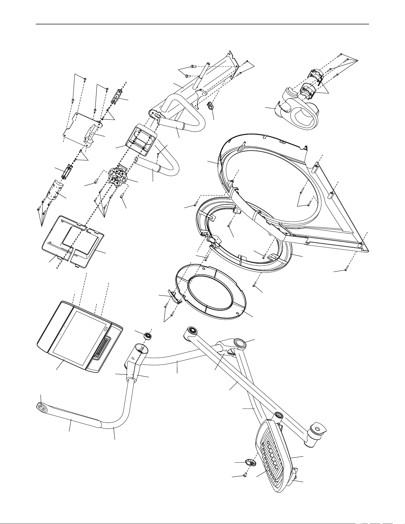
37
EXPLODED DRAWING A
4
37
81
54
63
71
73
101
101
101
92
124
5
101
50
101
156
147
145
150
128
116
101
101
5
50
147
148
151
149
46
52
45
44
47
49
68
67
70
72
76
95
127
154
143
149
94
7
79
150
152
153
101
101
63
Model No. NTEL71423-INT.2 R0823A
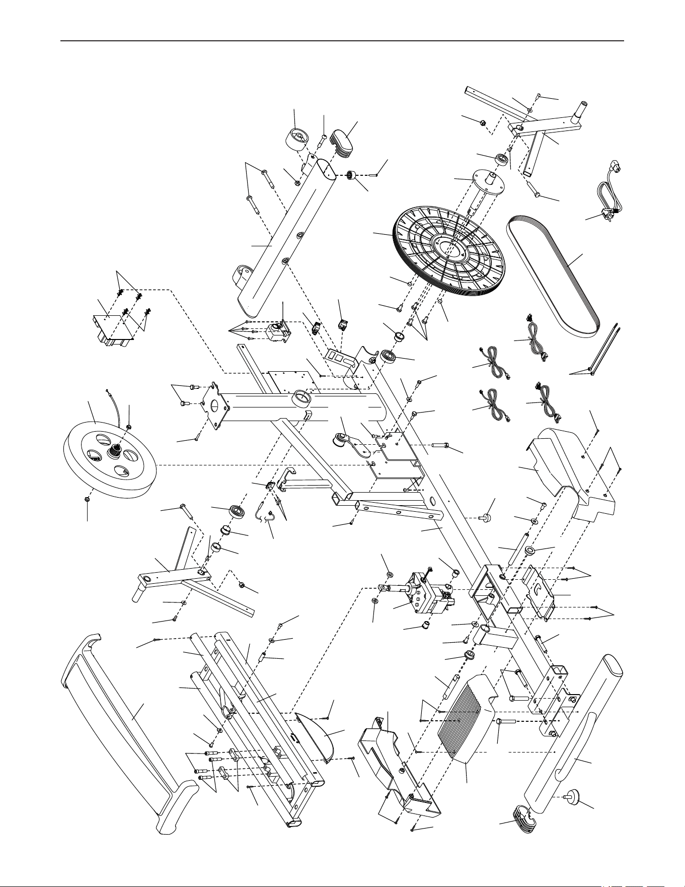
38
EXPLODED DRAWING B
113
84
17
25
48
93
115
115
114
6
18
30
30
34
104
26
109
112
23
19
26
107
20
135
108
86
78
43
43
82
82
40
9
88
89
91
36
1
11
24
110
119
111
146
28
102
102
26
9
40
42
20
78
86
135
108
39
38
50
10
16
16
80
80
62
2
130
122
125
125
141
141
131
130
130
130
155
155
101
101
101
101
101
101
15
121
121
105
105
103
103
14
14
106
12
21
35
27
13
33
133
41
31
92
101
90
90
90
27
157
161
101
22
101
Model No. NTEL71423-INT.2 R0823A
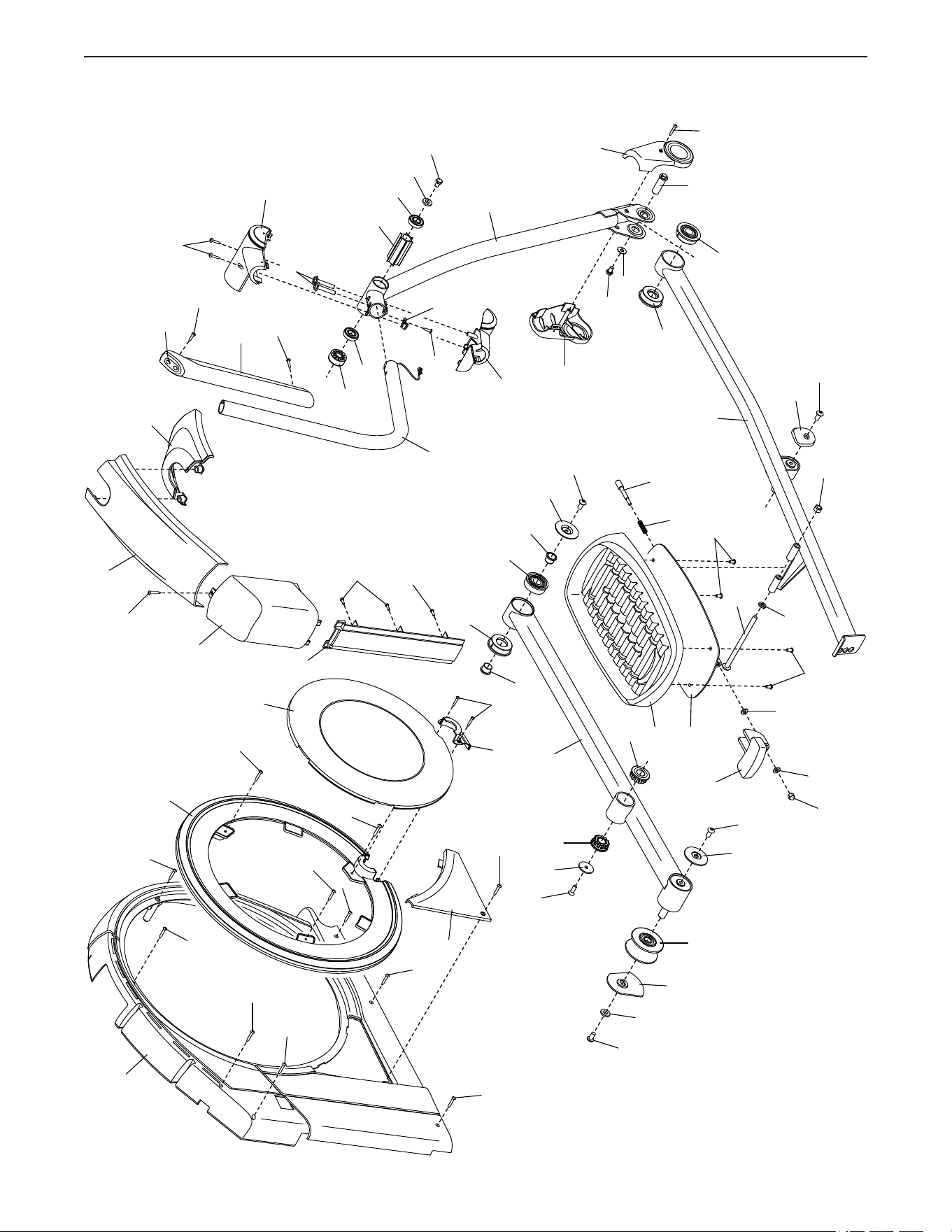
39
EXPLODED DRAWING C
74
124
50
50
5
5
116
5
101
32
32
95
127
137
138
139
140
141
141
142
58
57
57
125
125
87
59
99
123
77
95
56
55
120
56
51
53
95
98
95
8
71
126
126
101
101
101
3
136
85
144
26
29
75
117
118
101
64
60
101
101
101
61
66
65
69
83
101
82
96
129
82
97
100
100
54
134
132
158
159
160
101
101
Model No. NTEL71423-INT.2 R0823A
Part No. 446544 R0823A Printed in China © 2023 iFIT Inc.
To order replacement parts, please see the front cover of this manual. To help us assist you, be prepared to
provide the following information when contacting us:
• the model number and serial number of the product (see the front cover of this manual)
• the name of the product (see the front cover of this manual)
• the key number and description of the replacement part(s) (see the PART LIST and the EXPLODED DRAWING
near the end of this manual)
ORDERING REPLACEMENT PARTS
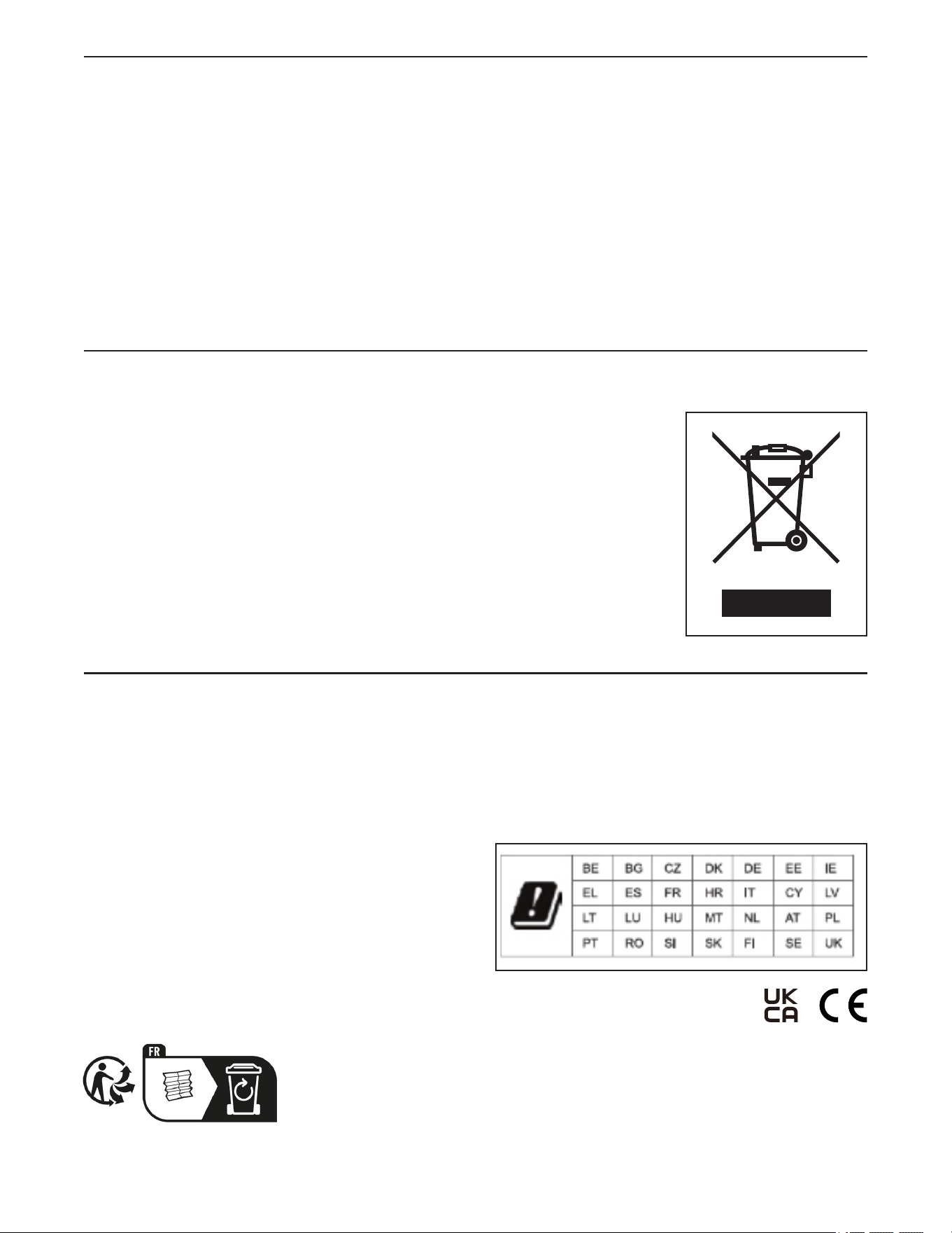
This electronic product must not be disposed of in municipal waste. To
preserve the environment, this product must be recycled after its useful life
as required by law.
Please use recycling facilities that are authorized to collect this type of waste in
your area. In doing so, you will help to conserve natural resources and improve
European standards of environmental protection. If you require more information
about safe and correct disposal methods, please contact your local city office or
the establishment where you purchased this product.
RECYCLING INFORMATION
UK/EU DECLARATION OF CONFORMITY
NTEL71423-INT contains the MP14-ARGON2 Tablet.
Hereby, iFIT Health & Fitness declares that the radio equipment type MP14-ARGON2 is in compliance with Directive 2014/53/EU and Radio
Equipment Regulation 2017.
iFIT Health & Fitness, 1500 S 1000 W, Logan, UT 84320, USA
This declaration of conformity is issued under the sole responsibility of the manufacturer.
Object of the declaration: FCCID OMC415321 - Broadcast Frequency Bands and Maximum EIRP power: 2.4G WIFI:19.08dBm; 5G
WIFI:18.42dBm; BT EDR:9.88dBm; BT BLE:9.59dBm.
Operations in the 5.15-5.35GHz band are restricted to indoor usage
only in following Countries:
Certification: Article 3.1a - Safety EN 62479:2010, EN 62368-1:2014/
AC:2015, Article 3.1b – EMC EN 301 489-1, 2.2.3, EN 301 489-17
V3.2.4, Article 3.2 – Radio parameters EN 300 328 V2.2.2, EN 301
893 V2.1.1
UK Representative: ICON Health & Fitness Ltd, Unit 1D The
Gateway, Fryers Way, Silkwood Park, Ossett, WF5 9TJ, United
Kingdom
iFIT Health & Fitness SAS Business Park, 5 Rue Alfred de Vigny
78112 Fourqueux, France