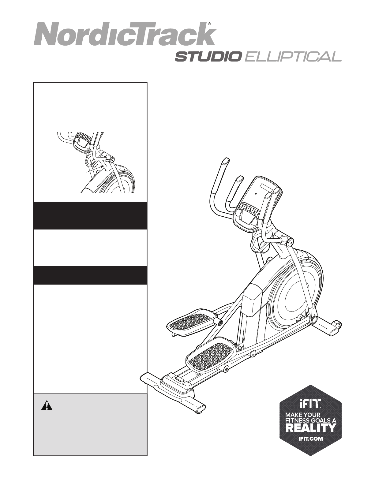
USER’S MANUAL
Serial Number
Decal
CAUTION
Read all precautions and
instructions in this manual before
using this equipment. Keep this
manual for future reference.
Model No. NTEL05621.2
Serial No.
Write the serial number in the space
above for reference.
nordictrack.com
To register your product and
activate your warranty today,
go to my.nordictrack.com.
For service at any time, go to
support.nordictrack.com.
Or call 1-800-TO-BE-FIT
(1-800-862-3348)
Mon.–Fri. 6 a.m.–6 p.m. MT
Sat. 8 a.m.–12 p.m. MT
Please do not contact the store.
REGISTER YOUR
PRODUCT
CUSTOMER CARE
2
TABLE OF CONTENTS
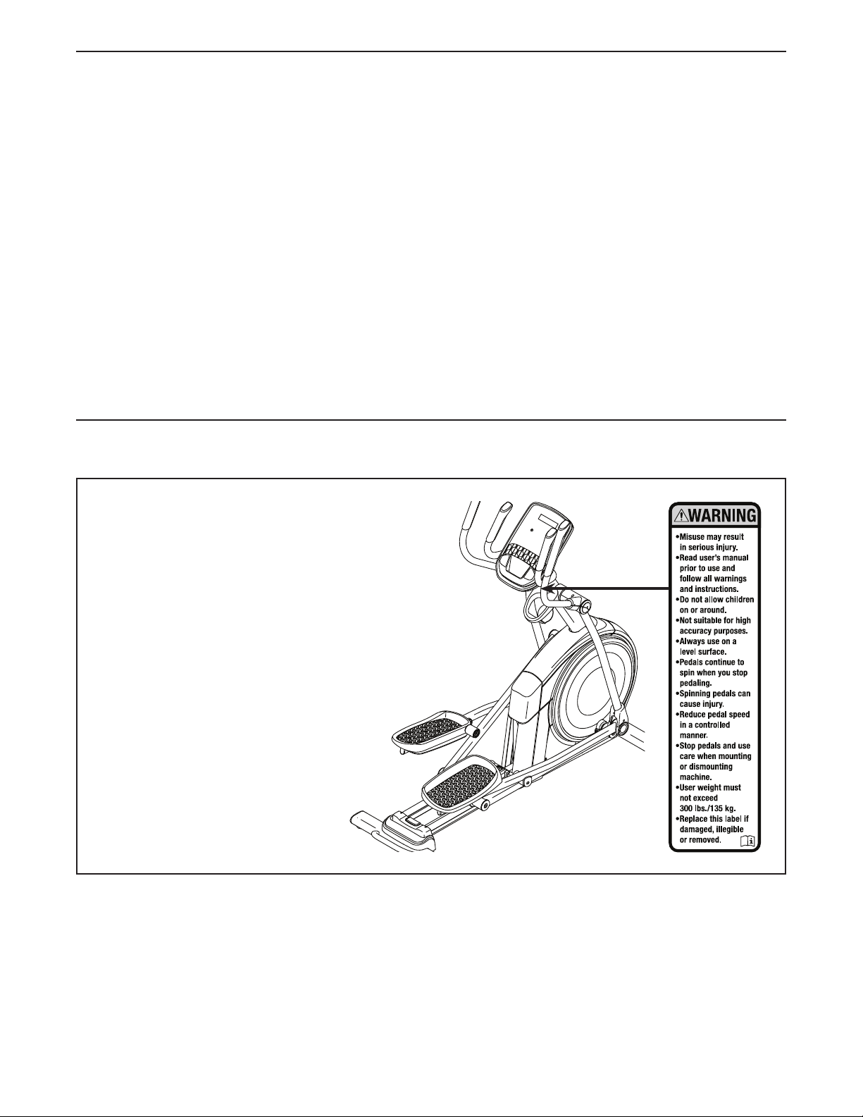
WARNING DECAL PLACEMENT
This drawing shows the location(s) of the warning
decal(s). If a decal is missing or illegible, see
the front cover of this manual and request a
free replacement decal. Apply the decal in the
location shown. Note: The decal(s) may not be
shown at actual size.
WARNING DECAL PLACEMENT . . . . . . . . . . . . . . . . . . . . . . . . . . . . . . . . . . . . . . . . . . . . . . . . . . . . . . . . . . . . . . .2
IMPORTANT PRECAUTIONS . . . . . . . . . . . . . . . . . . . . . . . . . . . . . . . . . . . . . . . . . . . . . . . . . . . . . . . . . . . . . . . . . .3
BEFORE YOU BEGIN. . . . . . . . . . . . . . . . . . . . . . . . . . . . . . . . . . . . . . . . . . . . . . . . . . . . . . . . . . . . . . . . . . . . . . . .5
PART IDENTIFICATION CHART. . . . . . . . . . . . . . . . . . . . . . . . . . . . . . . . . . . . . . . . . . . . . . . . . . . . . . . . . . . . . . . .6
ASSEMBLY . . . . . . . . . . . . . . . . . . . . . . . . . . . . . . . . . . . . . . . . . . . . . . . . . . . . . . . . . . . . . . . . . . . . . . . . . . . . . . . .7
HOW TO USE THE ELLIPTICAL . . . . . . . . . . . . . . . . . . . . . . . . . . . . . . . . . . . . . . . . . . . . . . . . . . . . . . . . . . . . . .17
HOW TO USE THE CONSOLE. . . . . . . . . . . . . . . . . . . . . . . . . . . . . . . . . . . . . . . . . . . . . . . . . . . . . . . . . . . . . . . .19
FCC INFORMATION . . . . . . . . . . . . . . . . . . . . . . . . . . . . . . . . . . . . . . . . . . . . . . . . . . . . . . . . . . . . . . . . . . . . . . . .26
MAINTENANCE AND TROUBLESHOOTING . . . . . . . . . . . . . . . . . . . . . . . . . . . . . . . . . . . . . . . . . . . . . . . . . . . . . 27
EXERCISE GUIDELINES . . . . . . . . . . . . . . . . . . . . . . . . . . . . . . . . . . . . . . . . . . . . . . . . . . . . . . . . . . . . . . . . . . . .29
PART LIST. . . . . . . . . . . . . . . . . . . . . . . . . . . . . . . . . . . . . . . . . . . . . . . . . . . . . . . . . . . . . . . . . . . . . . . . . . . . . . . .31
EXPLODED DRAWING. . . . . . . . . . . . . . . . . . . . . . . . . . . . . . . . . . . . . . . . . . . . . . . . . . . . . . . . . . . . . . . . . . . . . .33
ORDERING REPLACEMENT PARTS . . . . . . . . . . . . . . . . . . . . . . . . . . . . . . . . . . . . . . . . . . . . . . . . . . Back Cover
LIMITED WARRANTY. . . . . . . . . . . . . . . . . . . . . . . . . . . . . . . . . . . . . . . . . . . . . . . . . . . . . . . . . . . . . . . Back Cover
NORDICTRACK and IFIT are registered trademarks of ICON Health & Fitness, Inc. App Store is a trademark of
Apple Inc., registered in the U.S. and other countries. Android and Google Play are trademarks of Google LLC.
The Bluetooth
®
word mark and logos are registered trademarks of Bluetooth SIG, Inc. and are used under license.
IOS is a trademark or registered trademark of Cisco in the U.S. and other countries and is used under license.

3
WARNING: To reduce the risk of serious injury, read all important precautions and
instructions in this manual and all warnings on your elliptical before using your elliptical. ICON
assumes no responsibility for personal injury or property damage sustained by or through the
use of this product.
IMPORTANT PRECAUTIONS
1. It is the responsibility of the owner to ensure
that all users of the elliptical are adequately
informed of all precautions.
2. Keep children under age 16 and pets away
from the elliptical at all times.
3. Consult your health care provider before
beginning any exercise program. This is
especially important for persons over age
35 or persons with pre-existing health
problems.
4. Consult your health care provider before
beginning or continuing any exercise pro-
gram during pregnancy. Use the elliptical
only as authorized by your health care
provider.
5. The elliptical is not intended for use by
persons with reduced physical, sensory, or
mental capabilities or lack of experience and
knowledge, unless they are given supervi-
sion or instruction about use of the elliptical
by someone responsible for their safety.
6. Use the elliptical only as described in this
manual.
7. The elliptical is intended for home use only.
Do not use the elliptical in a commercial,
rental, or institutional setting.
8. Keep the elliptical indoors, away from mois-
ture and dust. Do not put the elliptical in a
garage or covered patio, or near water.
9. Place the elliptical on a level surface, with at
least 3 ft. (0.9 m) of clearance in the front and
rear of the elliptical and 2 ft. (0.6 m) on each
side. To protect the floor or carpet from dam-
age, place a mat under the elliptical.
10. Inspect and properly tighten all parts each
time the elliptical is used. Replace any worn
parts immediately. Use only manufacturer-
supplied parts.
11. The elliptical should not be used by persons
weighing more than 300 lbs. (135 kg).
12. Wear appropriate clothes while exercising;
do not wear loose clothes that could become
caught on the elliptical. Always wear athletic
shoes for foot protection while exercising.
13. Hold the handlebars or the upper body arms
when mounting, dismounting, or using the
elliptical. Before mounting or dismounting,
bring the pedals to a stop with the pedal
on the mounting or dismounting side in its
lowest position.
14. The elliptical does not have a freewheel; the
pedals will continue to move until the fly-
wheel stops. Reduce your pedaling speed in
a controlled way.
15. Keep your back straight while using the ellip-
tical; do not arch your back.
16. Over exercising may result in serious injury
or death. If you feel faint, if you become short
of breath, or if you experience pain while
exercising, stop immediately and cool down.
4
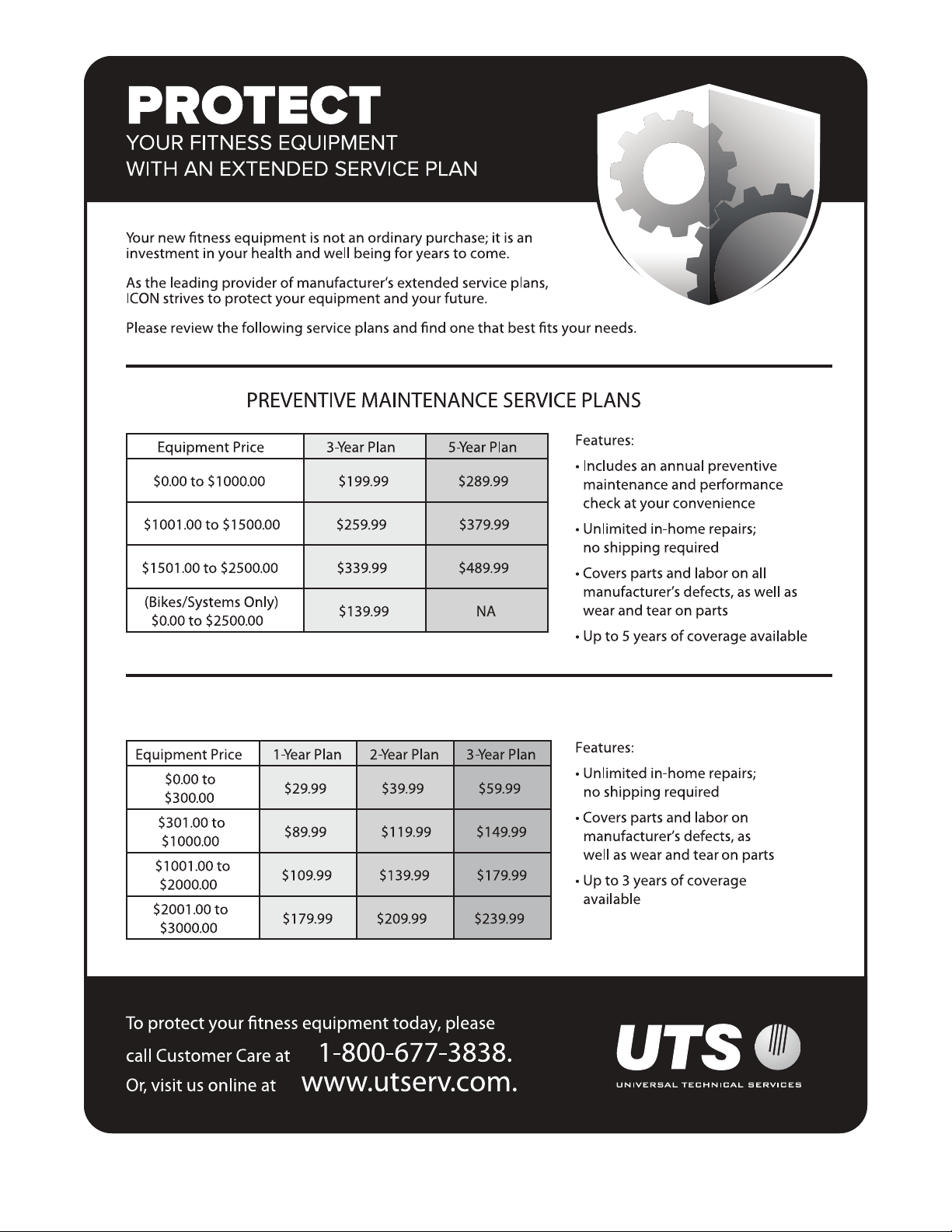
all
STANDARD SERVICE PLANS
5
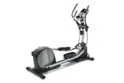
Thank you for selecting the revolutionary
NORDICTRACK
®
STUDIO ELLIPTICAL. The STUDIO
ELLIPTICAL provides an impressive selection of fea-
tures designed to make your workouts at home more
effective and enjoyable.
For your benefit, read this manual carefully before
you use the elliptical. If you have questions after
reading this manual, please see the front cover of this
manual. To help us assist you, note the product model
number and serial number before contacting us. The
model number and the location of the serial number
decal are shown on the front cover of this manual.
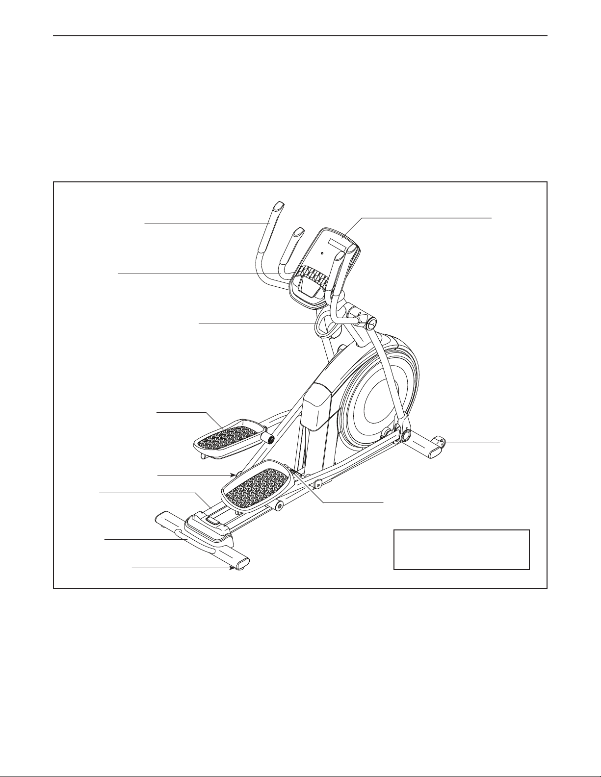
Before reading further, please familiarize yourself with
the parts that are labeled in the drawing below.
Accessory Tray
Handlebar
Upper Body Arm
Pedal
Roller
Handle
Ramp
Ramp Handle
Console
BEFORE YOU BEGIN
Wheel
Leveling Foot
Length: 5 ft. 8 in. (173 cm)
Width: 2 ft. 1 in. (64 cm)
6
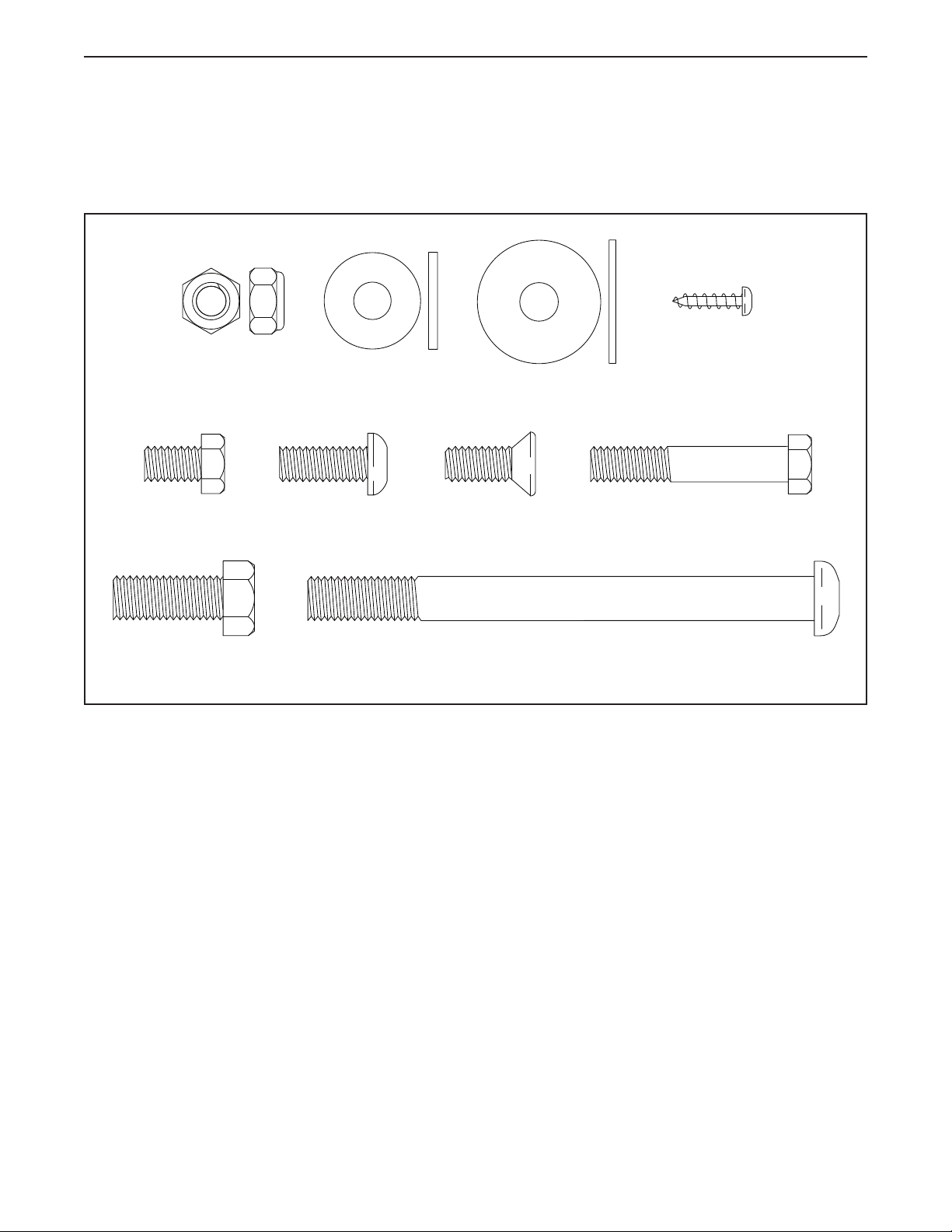
PART IDENTIFICATION CHART
Use the drawings below to identify the small parts needed for assembly. The number in parentheses below each
drawing is the key number of the part, from the PART LIST near the end of this manual. The number following the
key number is the quantity needed for assembly. Note: If a part is not in the hardware kit, check to see if it
has been preassembled. Extra parts may be included.
M10 x 115mm Screw
(104)–4
M8 x 13mm
Screw (82)–4
M8 x 45mm Bolt
(96)–4
M8 x 20mm Flat
Head Screw (120)–2
M8 x 20mm
Screw (95)–2
M10 x 25mm
Screw (92)–2
M8 Locknut
(102)–4
M4 x 16mm
Screw (101)–22
M8 x 22mm
Washer (129)–2
M8 x 28mm
Washer (97)–2
7
2. With the help of a second person, place some of
the packing materials (not shown) under the rear
of the Frame (1). Have the second person hold
the Frame to prevent it from tipping while you
complete this step.
Attach the Rear Stabilizer (2) to the Frame (1)
with two M10 x 115mm Screws (104).
Then, remove the packing materials from under
the rear of the Frame (1).
2
1
2
104
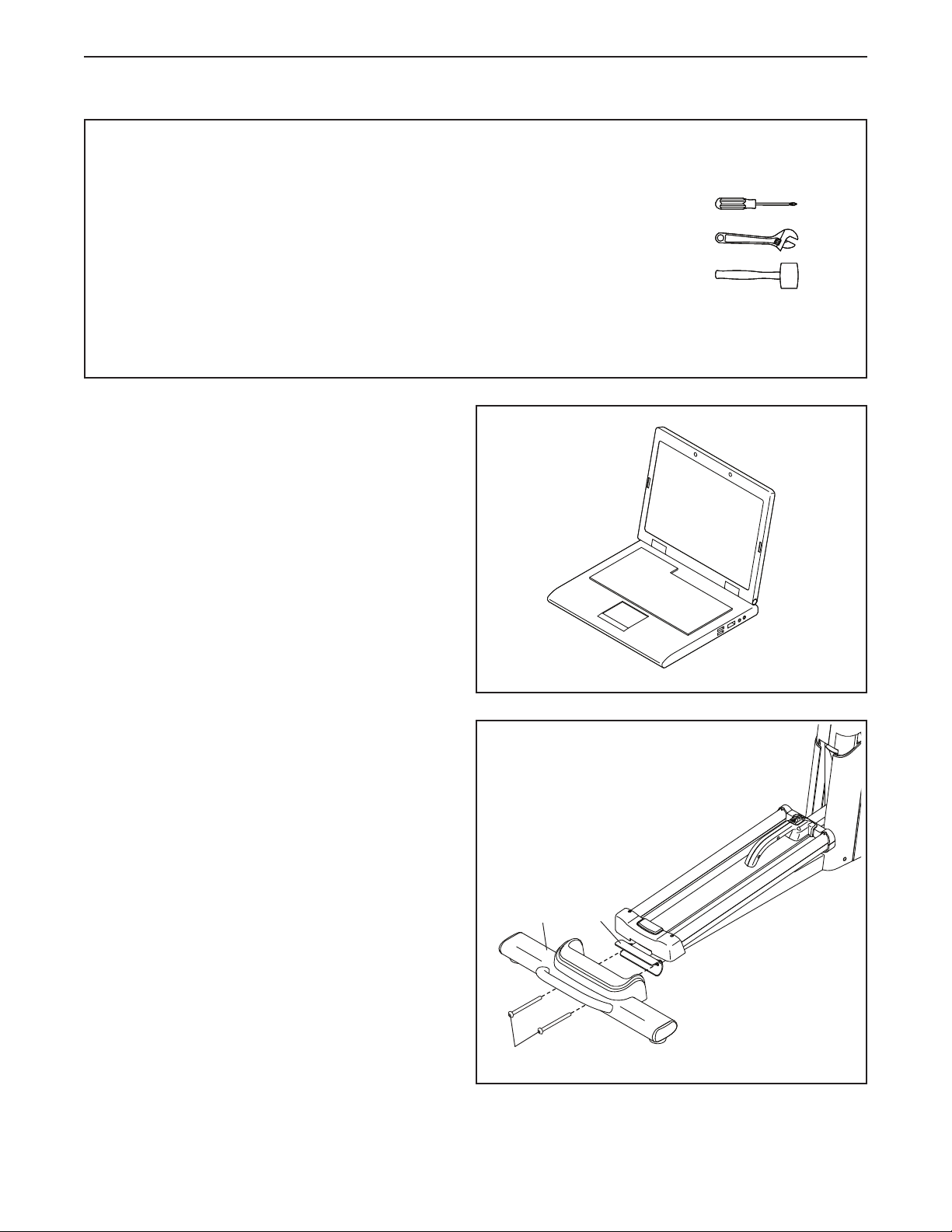
• Assembly requires two persons.
• Place all parts in a cleared area and remove the
packing materials. Do not dispose of the packing
materials until you fi nish all assembly steps.
• Left parts are marked “L” or “Left” and right parts
are marked “R” or “Right.”
• To identify small parts, see page 6.
• In addition to the included tool(s), assembly
requires the following tools:
one Phillips screwdriver
two adjustable wrenches
one rubber mallet
Assembly may be easier if you have a set of
wrenches. To avoid damaging parts, do not use
power tools.
ASSEMBLY
1
1. Go to my.nordictrack.com on your computer
and register your product.
• documents your ownership
• activates your warranty
• ensures priority customer support if assistance
is ever needed
Note: If you do not have internet access, call
Customer Care (see the front cover of this
manual) and register your product.
8
3
6
4
3. With the help of a second person, place some
of the packing materials (not shown) under the
front of the Frame (1). Have the second per-
son hold the Frame to prevent it from tipping
while you complete this step.
Attach the Front Stabilizer (6) to the Frame (1)
with two M10 x 115mm Screws (104).
Then, remove the packing materials from under
the front of the Frame (1).
1
104
77
59
45
95
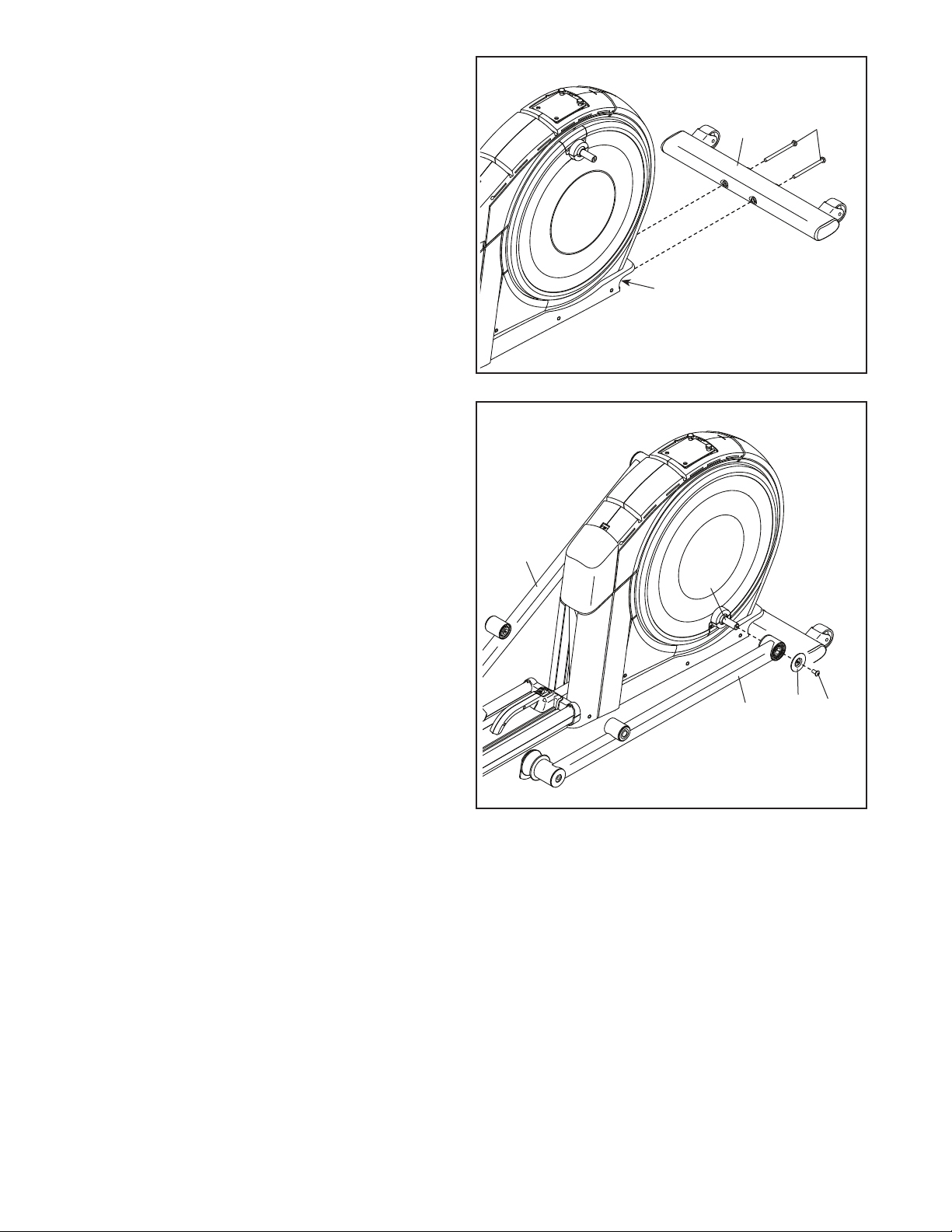
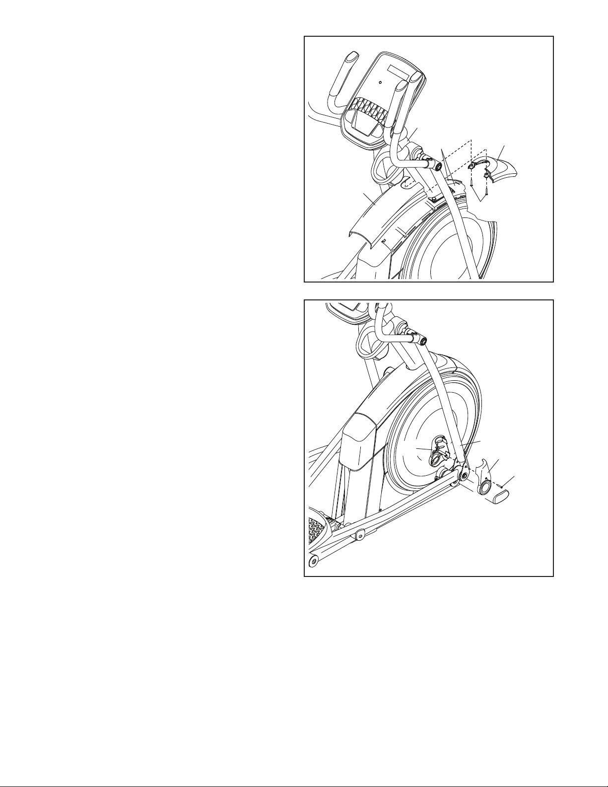
4. Identify the Right Roller Arm (59), orient it as
shown, and slide it onto the right Crank Arm (20).
Attach the Right Roller Arm (59) with an
M8 x 20mm Screw (95) and a Crank Cover (77).
Repeat this step for the Left Roller Arm (45).
20
9
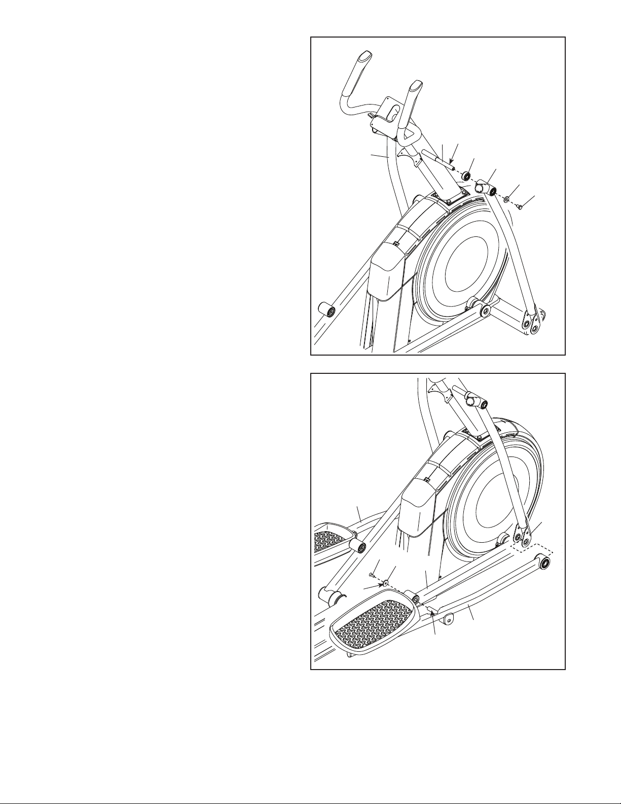
5
6. Locate the wire tie (A) in the lower end of the
Upright (4). Tie the wire tie to the Upper Wire
(110). Then, pull the upper end of the wire
tie until the Upper Wire is routed through the
Upright.
Tip: To prevent the Upper Wire (110) from
falling into the Upright (4), secure the Upper
Wire with the wire tie (A).
4
110
A
6
5. Tip: Avoid pinching the Upper Wire (110).
Have a second person hold the Upright (4) on
the Frame (1).
Tip: Two M10 x 25mm Screws (92) are
preattached to the Frame (1).
Attach the Upright (4) to the Frame (1) with two
additional M10 x 25mm Screws (92); start both
Screws, and then tighten all four Screws.
Avoid pinching the
Upper Wire (110)
4
1
92
92
110
A
10
7
7. Apply grease to the axle on the right side of the
Upright (4).
Next, slide a Pivot Spacer (54) onto the right
side of the Upright (4).
Then, identify the Right Upper Body Leg (60),
orient it as shown, and slide it onto the right side
of the Upright (4).
Attach the Right Upper Body Leg (60) with an
M8 x 13mm Screw (82) and an M8 x 28mm
Washer (97).
Repeat this step for the Left Upper Body
Leg (46).
46
4
Grease
8
60
60
54
82
97
8. Orient the Right Pedal Arm (58) as shown, and
then apply grease to the axle.
Insert the Right Pedal Arm (58) into the Right
Upper Body Leg (60) and into the Right Roller
Arm (59).
Attach the Right Pedal Arm (58) to the Right
Roller Arm (59) with an M8 x 20mm Flat Head
Screw (120) and a Retainer (55); make sure
that the flat side (B) of the Retainer is facing
the Right Roller Arm.
Repeat this step for the Left Pedal Arm (44).
Grease
55
B
58
44
120
59
11
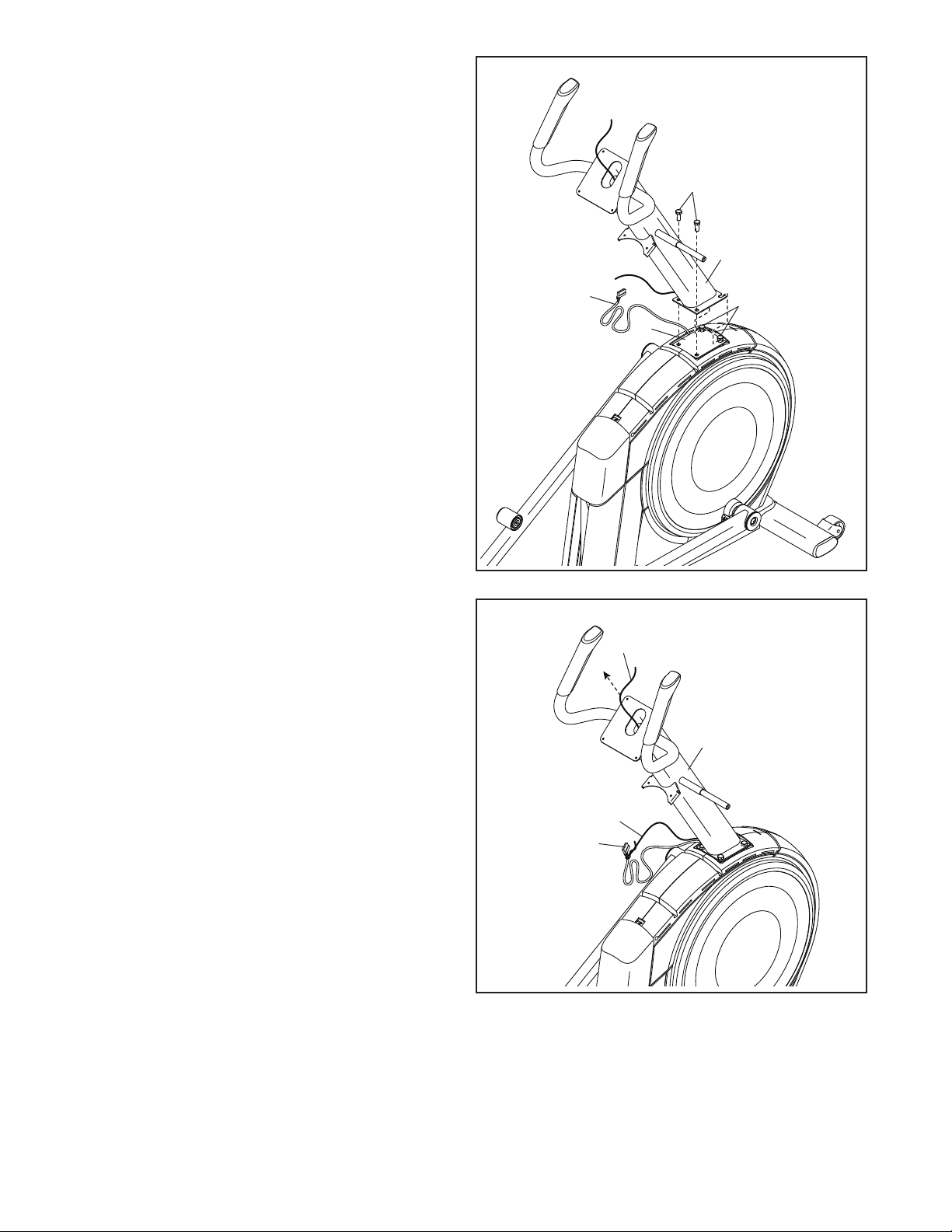
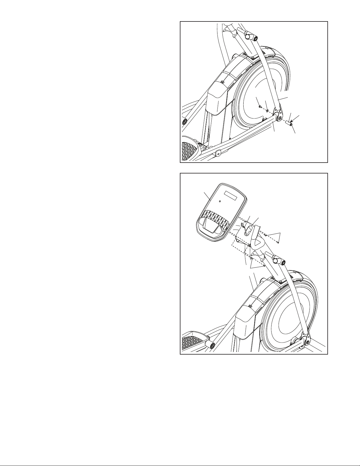
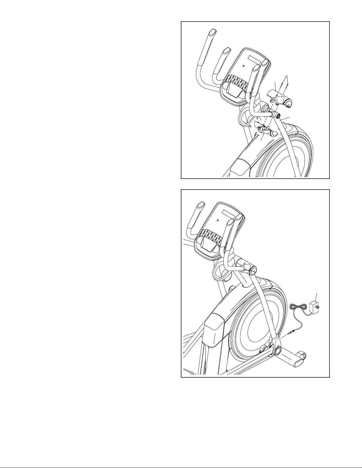
9
10
7
10. Untie and discard the wire tie on the Upper
Wire (110).
While a second person holds the Console (7)
near the Upright (4), plug the Upper Wire (110)
into the receptacle on the Console. Tip: The
wire connector should slide in easily and
snap into place with an audible click. If it
does not, turn the connector and try again.
Insert the excess wire into the Upright (4) or into
the Console (7).
Tip: Avoid pinching the Upper Wire (110).
Attach the Console (7) to the Upright (4) with
four M4 x 16mm Screws (101); start all of the
Screws, and then tighten them.
101
9. Apply grease to one of the Pedal Arm Axles (64).
Insert the Pedal Arm Axle (64) into the Right
Upper Body Leg (60) and the Right Pedal Arm
(58) from the direction shown.
Next, slide an M8 x 22mm Washer (129) onto an
M8 x 13mm Screw (82), and tighten the Screw a
few turns into the Pedal Arm Axle (64).
Then, tighten both M8 x 13mm Screws (82) at
the same time.
Repeat this step on the other side of the
elliptical.
82
82
129
60
64
Grease
58
4
110
101
Avoid pinching the
Upper Wire (110)
12
11
12
12. Orient the Accessory Tray (37) as shown, and
attach it to the Upright (4) with two M4 x 16mm
Screws (101).
11. Orient the Rear Console Cover (80) as shown,
and attach it to the Upright (4) with two
M4 x 16mm Screws (101).
Then, orient the Front Console Cover (79) as
shown, and attach it to the Rear Console Cover
(80) with two M4 x 16mm Screws (101).
79
4
4
80
101
101
101
101
37
13
13
101
81
37
13. Orient a Lower Tray Cover (81) as shown, and
attach it to the right side of the Accessory Tray
(37) with two M4 x 16mm Screws (101).
Repeat this step on the other side of the
elliptical.
14
14. Identify the Right Upper Body Arm (61), orient it
as shown, and insert it into the Right Upper Body
Leg (60).
Attach the Right Upper Body Arm (61) with two
M8 x 45mm Bolts (96) and two M8 Locknuts
(102); make sure that the Locknuts are in the
hexagonal holes (C).
Repeat this step for the Left Upper Body
Arm (47).
60
61
47
96
102
C
14
75
4
117
101
73, 74
15. Orient the Front Shield Cover (117) and the
Center Shield Cover (75) around the Upright (4)
as shown. Then, attach them to each other with
two M4 x 16mm Screws (101).
Then, press the Front Shield Cover (117) and the
Center Shield Cover (75) into the Left and Right
Shields (73, 74).
15
16. Identify the Right Leg Inner Cover (83), orient it
as shown, and insert it through the Right Upper
Body Leg (60).
Next, identify the Right Leg Outer Cover (69),
orient it as shown, and press it onto the Right
Leg Inner Cover (83).
Attach the Right Leg Outer and Inner Covers
(69, 83) to each other with an M4 x 16mm
Screw (101).
Repeat this step on the other side of the
elliptical.
60
101
69
16
83
15
17
65
60
101
66
17. Orient the Right Arm Front and Rear
Covers (65, 66) around the Right Upper Body
Leg (60) as shown, and then attach them with
two M4 x 16mm Screws (101).
Repeat this step on the other side of the
elliptical.
18. Make sure that all parts are properly tight-
ened before you use the elliptical. Place a mat
beneath the elliptical to protect the floor. Note:
Extra parts may be included.
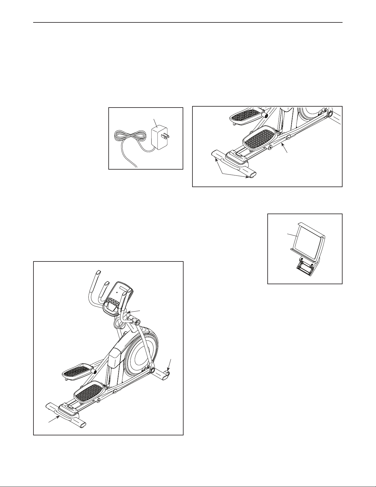
Next, plug the Power Adapter (119) into the
receptacle on the front of the elliptical.
Then, plug the Power Adapter (119) into an
outlet (see HOW TO PLUG IN THE POWER
ADAPTER on page 17).
119
18

16
19
19. IMPORTANT: You must activate your Console
(7) to begin using its exclusive features.
First, press any button on the Console (7) to turn
on the power.
Then, using your smartphone or tablet, go to
iFit.com/activate and follow the instructions to
activate the Console (7).
Note: If you do not have a smartphone or tablet,
use your computer to go to iFit.com/activate for
an alternate way to activate the Console (7). If
you do not have a computer, call Customer Care
(see the front cover of this manual).
7
17
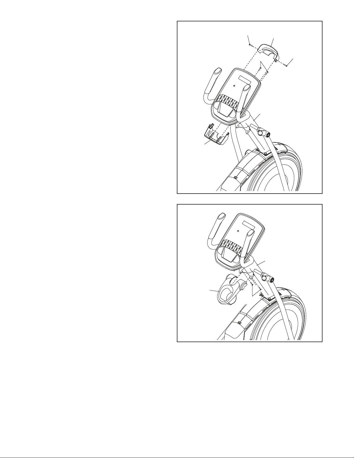
HOW TO PLUG IN THE POWER ADAPTER
IMPORTANT: If the elliptical has been exposed to
cold temperatures, allow it to warm to room tem-
perature before you plug in the power adapter (A).
If you do not do this, you may damage the console
displays or other electronic components.
Plug the power adapter
(A) into the receptacle
on the front of the
elliptical. Then, plug
the power adapter
into an appropriate
outlet that is properly
installed in accordance
with all local codes and
ordinances.
HOW TO MOVE THE ELLIPTICAL
Due to the size and weight of the elliptical, moving
it requires two persons. Stand in front of the elliptical,
hold the upright (B), and place one foot against one of
the wheels (C). Pull on the upright and have a second
person lift the handle (D) until the elliptical will roll on
the wheels. Carefully move the elliptical to the desired
location, and then lower it to the floor.
HOW TO LEVEL THE ELLIPTICAL
If the elliptical rocks slightly on your floor during use,
turn one or both of the leveling feet (E) beneath
the rear stabilizer or turn the leveling foot (F) under
the center of the frame until the rocking motion is
eliminated.
THE OPTIONAL TABLET HOLDER
The optional tablet
holder (G) will hold
your tablet securely
in place and enable
you to use your tablet
while you exercise. The
optional tablet holder is
designed for use with
most full-size tablets.
To purchase a tablet
holder, please see
the front cover of this
manual.
A
B
D
C
E
F
G
HOW TO USE THE ELLIPTICAL
18
HOW TO CHANGE THE INCLINE OF THE RAMP
To vary the motion of
the pedals, you can
change the incline
of the ramp. To raise
the ramp, press the
latch button (H), and
then pull the ramp
handle (I) upward to
the desired incline
level.
To lower the ramp, press the latch button (H), pull the
ramp handle (I), and lower the ramp to the desired
incline level. Then, release the latch button and
engage the latch pin into one of the adjustment holes
in the frame. Make sure that the latch pin is firmly
engaged in one of the adjustment holes in the
frame.
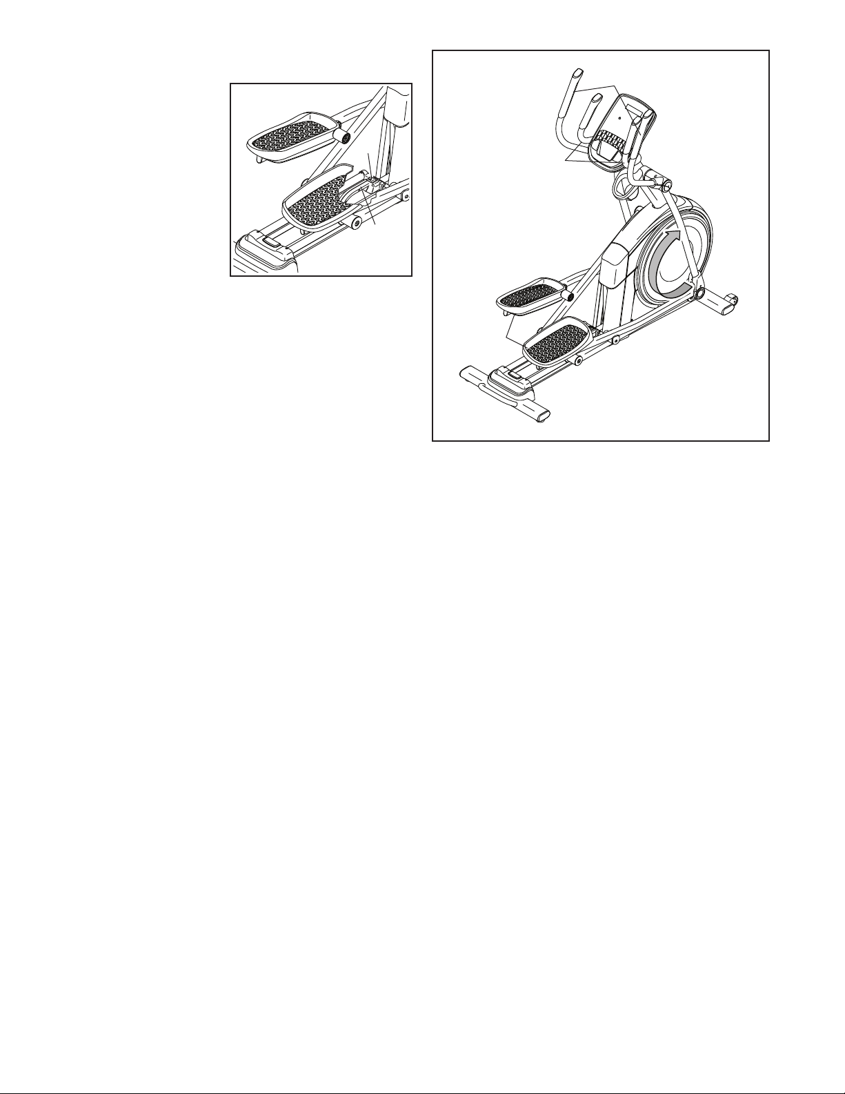
HOW TO EXERCISE ON THE ELLIPTICAL
See the drawing at the right. To mount the elliptical,
hold the handlebars (J) or the upper body arms (K)
and step onto the pedal (L) that is in the lower position.
Then, step onto the other pedal. Push the pedals until
they begin to move with a continuous motion. Note:
The pedals can turn in either direction. It is recom-
mended that you turn the pedals in the direction
shown by the arrow; however, for variety, you can
turn the pedals in the opposite direction.
To dismount the elliptical, wait until the pedals (L) come
to a complete stop. Note: The elliptical does not
have a free wheel; the pedals will continue to move
until the flywheel stops. When the pedals are station-
ary, step off the higher pedal first. Then, step off the
lower pedal.
I
H
J
K
L
19
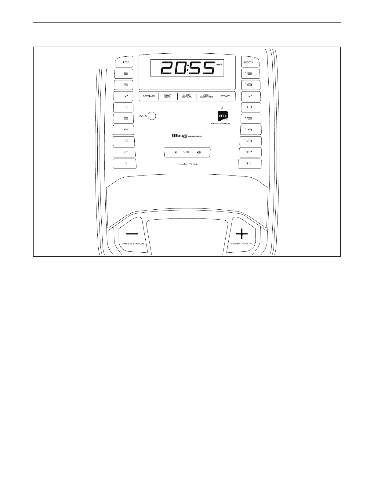
FEATURES OF THE CONSOLE
IMPORTANT: To activate your console and begin
using its exclusive features, see assembly step 19
on page 16.
The advanced console offers an array of features
designed to make your workouts more effective and
enjoyable.
When you use the manual mode of the console, you
can change the resistance of the pedals with the touch
of a button. As you exercise, the console will provide
continuous exercise feedback. You can even measure
your heart rate using a compatible heart rate monitor.
The console also offers unlimited iFit workouts when
you download the iFit app to your smart device and
connect it to the console.
With the iFit app, you can access a large and var-
ied library of iFit video workouts, create your own
workouts, track your workout results, and access many
other features.
Each iFit workout automatically changes the resistance
of the pedals as an iFit coach guides you through an
immersive and effective video workout.
In addition, you can connect your personal audio
player to the console sound system and listen to your
favorite music or audio books while you exercise.
To use the manual mode, see page 20. To use an
iFit workout, see page 22. To connect your heart
rate monitor to the console, see page 24. To
use the sound system, see page 24. To change
console settings, see page 25.
Note: If there is a sheet of plastic on the display,
remove the plastic. The console can display speed
and distance in either standard units or metric units.
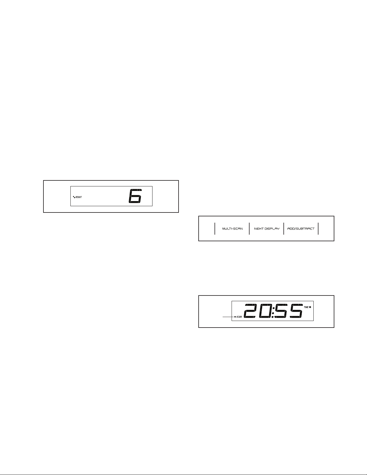
To change the unit of measurement, press the St/Met
button repeatedly.
CONSOLE DIAGRAM
HOW TO USE THE CONSOLE
20
HOW TO USE THE MANUAL MODE
1. Begin pedaling or press any button on the
console to turn on the console.
When you turn on the console, the display will turn
on. The console will then be ready for use.
2. Select the manual mode.
When you turn on the console, the manual mode
will be selected automatically.
3. Change the resistance of the pedals as desired.
Begin pedaling to start the manual mode.
You can change the resistance of the pedals by
pressing one of the numbered Resistance but-
tons or by pressing the Resistance increase and
decrease buttons.
Note: After you press a button, it will take a
moment for the pedals to reach the selected
resistance level.
4. Follow your progress with the displays.
The display can show the following workout
information:
Calories (CALS)—The approximate number of
calories you have burned.
Calories per Hour (CALS/HR)—The approximate
number of calories you are burning per hour.
Distance (MI or KM)—The distance that you have
pedaled in miles or kilometers. To change the unit
of measurement, press the St/Met button.
Pace—Your pedaling speed in minutes per mile
or minutes per kilometer. To change the unit of
measurement, press the St/Met button.
Pulse (BPM and heart symbol)—Your heart rate
when you use or a compatible heart rate monitor
(see step 5).
Resistance (RESIST)—The resistance level of the
pedals.
RPM—Your pedaling speed in revolutions per
minute (RPM).
Speed (MPH or KPH)—Your pedaling speed in
miles per hour or kilometers per hour. To change
the unit of measurement, press the St/Met button.
Time—The elapsed time.
Press the Next Display button repeatedly to view
the desired workout information in the display.
Scan mode—The console also has a scan mode
that will display workout information in a repeat-
ing cycle. To turn on the scan mode, press the
Multi-scan button; the scan indicator (A) and the
word SCAN will turn on in the display.
A

21
To manually advance the scan cycle, press the
Multi-scan button repeatedly.
To turn off the scan mode, press the Next Display
button; the scan indicator and the word SCAN will
turn off.
You can also customize the scan mode to display
only the desired workout information in the
repeating cycle.
To customize the scan mode, first press the
Next Display button repeatedly until the workout
information that you want to add to or remove from
the scan cycle appears in the display.
Next, press the Add/Subtract button to add or
remove that workout information from the scan
cycle. When workout information is added, its
indicator will turn on in the display. When workout
information is removed, its indicator will turn off.
Then, press the Multi-scan button to turn on the
scan mode.
Note: The console will show your heart rate in the
scan cycle automatically whenever it detects a
pulse from a heart rate monitor.
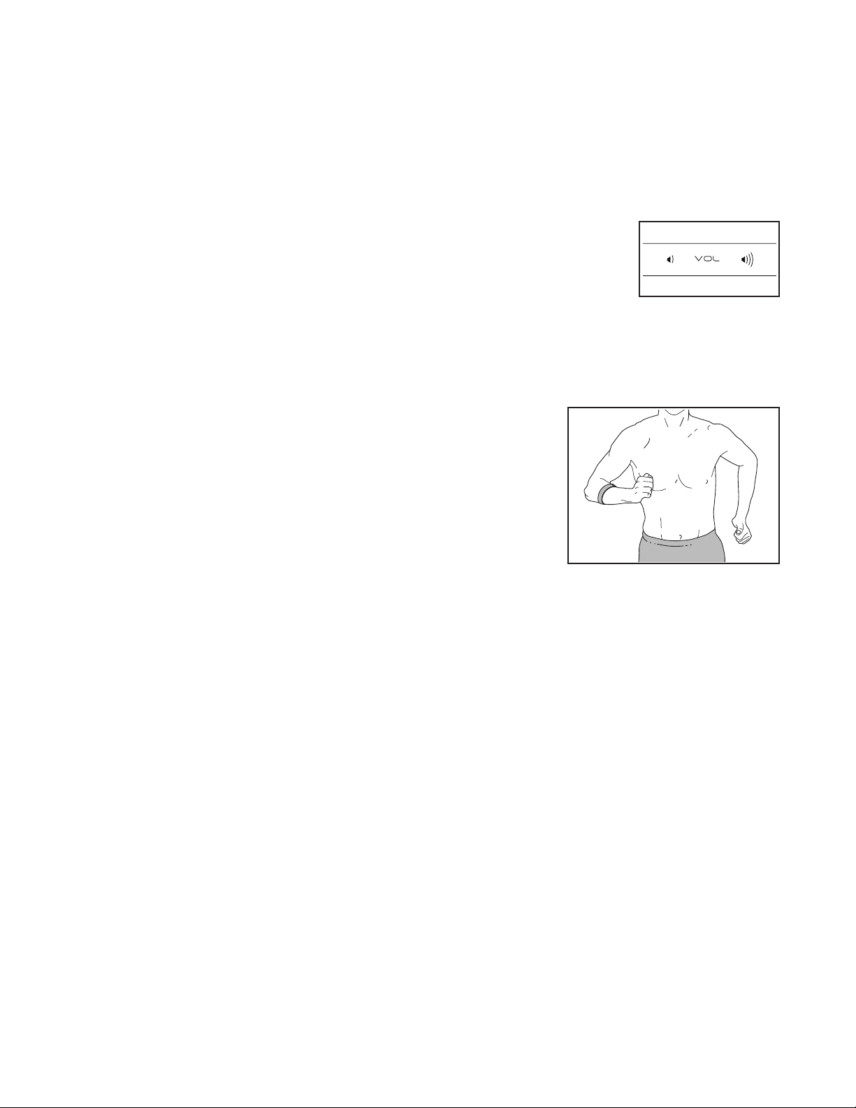
To change the volume
level of the console,
press the Vol increase
and decrease buttons.
To pause the console,
simply stop pedaling. When the console is paused,
the time will flash in the display. To continue your
workout, simply resume pedaling.
Note: The console can show speed and distance
in standard or metric units of measurement. To
change the unit of measurement, press the St/Met
button.
5. Wear a compatible heart rate monitor and
measure your heart rate if desired.
You can wear a compatible heart rate monitor to
measure your heart rate. Note: The console is
compatible with all Bluetooth
®
Smart heart rate
monitors.
A compatible heart rate monitor is included with
some models. If a heart rate monitor is included,
see THE HEART RATE MONITOR in this manual
to learn how to use it.
If this model does not include a compatible
heart rate monitor, see page 24 for informa-
tion about ordering one.
To connect a compatible heart rate monitor to the
console, press the iFit Sync button on the console;
the console pairing number will appear in the dis-
play. When a connection is established, the LED on
the console will flash red twice. When your heart-
beat is detected, your heart rate will be shown.
See HOW TO CONNECT YOUR HEART RATE
MONITOR TO THE CONSOLE on page 24 for
more information.
6. When you are finished exercising, the console
will turn off automatically.
If the pedals do not move for several seconds, the
console will pause and the time will flash in the
display. To resume your workout, simply resume
pedaling.
If the pedals do not move for several minutes and
the buttons are not pressed, the console will turn
off and the display will be reset.
Note: The console features a demo mode,
designed to be used if the elliptical is displayed in
a store. If the demo mode is turned on, the con-
sole will not turn off and the display will not be
reset when you fi nish exercising. To turn off the
demo mode, see HOW TO CHANGE CONSOLE
SETTINGS on page 25.

22
HOW TO USE AN IFIT WORKOUT
The console offers access to a large and varied library
of iFit workouts when you download the iFit app to your
smart device and connect it to the console.
Note: The console supports Bluetooth connections to
smart devices via the iFit app and to compatible heart
rate monitors. Other Bluetooth connections are not
supported.
1. Download and install the iFit app on your smart
device.
On your iOS
®
or Android™ smart device, open the
App Store℠ or the Google Play™ store, search
for the free iFit app, and then install the app on
your smart device. Make sure that the Bluetooth
option is enabled on your smart device.
Then, open the iFit app and follow the instructions
to set up an iFit account and customize settings.
Take time to explore the iFit app and learn about its
features and settings.
2. Connect your heart rate monitor to the console
if desired.
If you are connecting both your heart rate monitor
and your smart device to the console, you must
connect your heart rate monitor before you
connect your smart device. See HOW TO
CONNECT YOUR HEART RATE MONITOR TO
THE CONSOLE on page 24.
3. Connect your smart device to the console.
Press the iFit Sync button on the console; the
console pairing number will appear in the display.
Then, follow the instructions in the iFit app to con-
nect your smart device to the console.
When a connection is established, the LED on the
console will turn solid blue.
4. Select an iFit workout.
In the iFit app, touch the buttons at the bottom of
the screen to select either the main menu (Home
button) or the workout library (Browse button).
To select a workout from the main menu or the
workout library, simply touch the desired workout
button on the screen. Slide or flick the screen to
scroll upward or downward if necessary.
When you select a workout, the screen will show
an overview of the workout that includes details
such as the duration and distance of the workout
and the approximate number of calories you will
burn during the workout.
5. Start the workout.
Tou c h Start Workout to start the workout.
During some workouts, an iFit coach will guide you
through a video workout. Touch the screen in any
open space to view and select music, trainer voice,
and volume options for the workout.
If the resistance setting for the current segment of
the workout is too high or too low, you can manu-
ally override the setting by pressing the Resistance
buttons on the console. IMPORTANT: When
the current segment ends, the resistance will
automatically adjust to the resistance setting
programmed for the next segment.
Note: The calorie goal shown in the workout
description is an estimate of the number of
calories that you will burn during the workout.
The actual number of calories that you burn
will depend on various factors, such as your
weight. In addition, if you manually change the
resistance level during the workout, the number
of calories you burn will be affected.

23
To pause the workout, simply touch the screen
or stop pedaling. To continue the workout, simply
resume pedaling.
To end the workout, touch the screen to pause the
workout, and then follow the prompts on the screen
to end the workout and return to the main menu.
When the workout ends, a workout summary will
appear on the screen. If desired, you can select
options such as adding the workout to your sched-
ule or adding the workout to your favorites list.
Then, touch Save Workout to return to the main
menu.
6. Disconnect your smart device from the
console.
To disconnect your smart device from the console,
first select the disconnect option in the iFit app.
Then, press and hold the iFit Sync button on the
console until the LED on the console turns solid
green.
Note: All Bluetooth connections between the
console and other devices (including any smart
devices, heart rate monitors, and so forth) will be
disconnected.
7. When you are finished exercising, the console
will turn off automatically.
If the pedals are not moved for a few seconds, the
console will pause and the time will flash in the
display. To resume your workout, simply resume
pedaling.
If the pedals do not move for several minutes and
the buttons are not pressed, the console will turn
off and the display will be reset.
Note: The console features a display demo mode,
designed to be used if the elliptical is displayed in a
store. When the demo mode is turned on, the con-
sole will show a preset presentation. To turn off the
demo mode, see HOW TO CHANGE CONSOLE
SETTINGS on page 25.
24
HOW TO CONNECT YOUR HEART RATE MONITOR
TO THE CONSOLE
The console is compatible with all Bluetooth Smart
heart rate monitors.
To connect your Bluetooth Smart heart rate monitor to
the console, press the iFit Sync button on the console;
the console pairing number will appear in the display.
When a connection is established, the LED on the
console will flash red twice.
Note: If there is more than one compatible heart rate
monitor near the console, the console will connect to
the heart rate monitor with the strongest signal.
To disconnect your heart rate monitor from the console,
press and hold the iFit Sync button on the console until
the LED on the console turns solid green.
Note: All Bluetooth connections between the console
and other devices (including any tablets, heart rate
monitors, and so forth) will be disconnected.
HOW TO USE THE SOUND SYSTEM
To play music or audio books through the console
sound system while you exercise, plug a 3.5 mm male
to 3.5 mm male audio cable (not included) into the
jack on the console and into a jack on your personal
audio player; make sure that the audio cable is fully
plugged in. Note: To purchase an audio cable, see
your local electronics store.
Next, press the play but-
ton on your personal audio
player. Adjust the volume
level using the Vol increase
and decrease buttons on
the console or the volume
control on your personal audio player.
THE OPTIONAL HEART RATE MONITOR
Whether your
goal is to
burn fat or to
strengthen your
cardiovascular
system, the key
to achieving the
best results is
to maintain the
proper heart
rate during your
workouts. The optional heart rate monitor will enable
you to continuously monitor your heart rate while you
exercise, helping you to reach your personal fitness
goals. To purchase an optional heart rate monitor,
please see the front cover of this manual.
Note: The console is compatible with all Bluetooth
Smart heart rate monitors.
25
HOW TO CHANGE CONSOLE SETTINGS
1. Select the settings mode.
If you are using the manual mode, you must stop
pedaling and exit the workout before you can select
the settings mode.
To select the settings mode, press the Settings
button. The first settings screen will appear in the
display.
2. Navigate the settings mode.
While the settings mode is selected, you can
navigate through several settings screens. Press
the Next Display button repeatedly to select the
desired settings screen.
3. Change settings as desired.
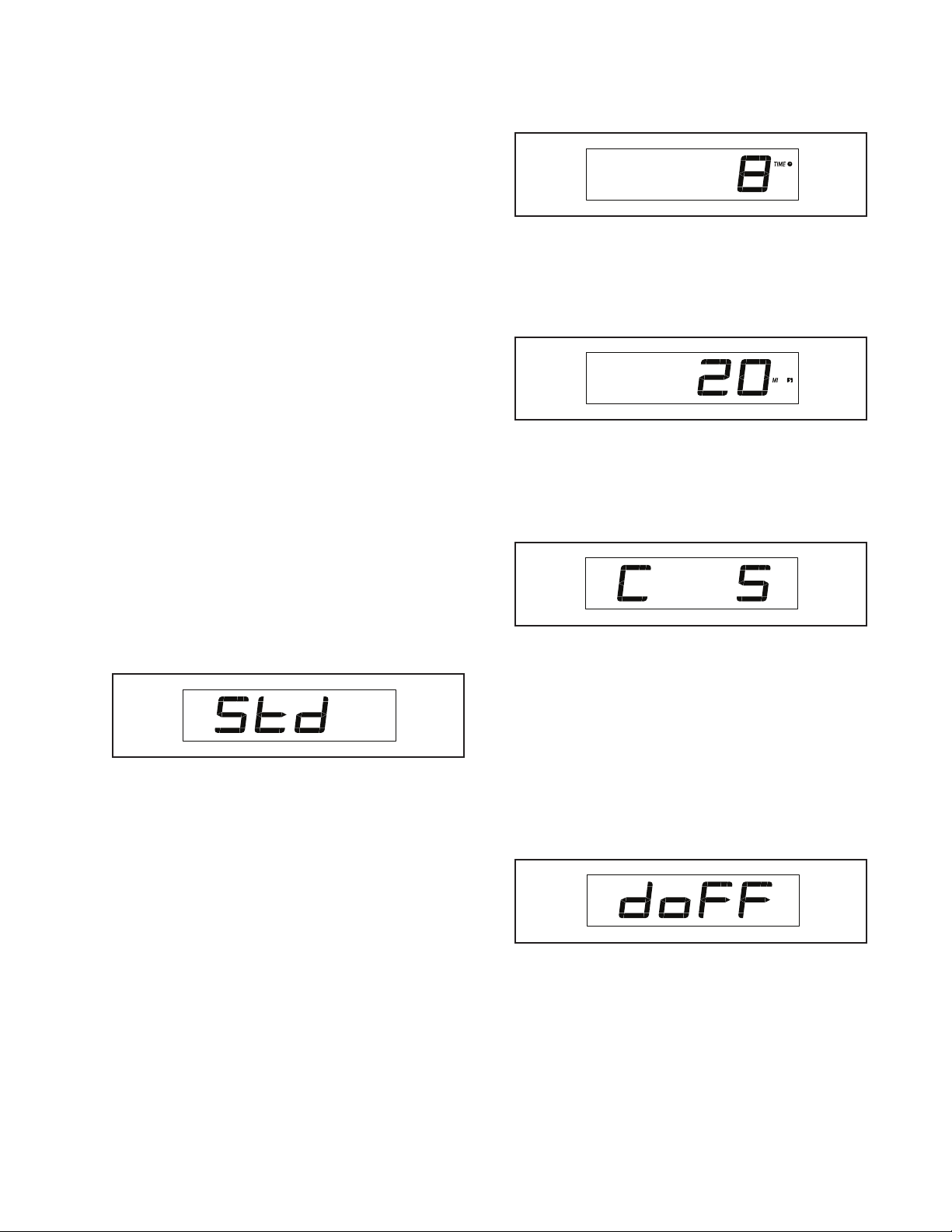
Software Version Number—The software version
number will appear in the display.
Unit of Measurement—The currently selected
unit of measurement will appear in the display. The
console can show speed and distance in standard
or metric units of measurement. To change the unit
of measurement, press the St/Met button repeat-
edly. To view workout information in standard units,
select STD. To view workout information in metric
units, select MET.
Display Test—This screen is intended to be used
by service technicians to identify whether the
display is working correctly.
Button Test—This screen is intended to be used
by service technicians to identify whether a certain
button is working correctly.
Total Time—The word TIME will appear in the
display. The display will show the total number of
hours that the elliptical has been used.
Total Distance—The letters MI or KM will appear
in the display. The display will show the total
distance (in miles or kilometers) that the elliptical
has been pedaled.
Contrast Level—The currently selected con-
trast level will appear in the display. Press the
Resistance increase and decrease buttons to
adjust the contrast level.
Demo Mode—The currently selected demo mode
option will appear in the display. The console
features a demo mode, designed to be used if the
elliptical is displayed in a store. If the demo mode
is turned on, the console will not turn off and the
display will not be reset when you fi nish exercising.
Press the Resistance increase button repeatedly
to select a demo mode option. To turn on the demo
mode, select DON. To turn off the demo mode,
select DOFF.
4. Exit the settings mode.
Press the Settings button to exit the settings mode.

26
FCC INFORMATION
This equipment has been tested and found to comply with the limits for a Class B digital device, pursuant to Part
15 of the FCC Rules. These limits are designed to provide reasonable protection against harmful interference
in a residential installation. This equipment generates, uses, and can radiate radio frequency energy and, if not
installed and used in accordance with the instructions, may cause harmful interference to radio communications.
However, there is no guarantee that interference will not occur in a particular installation. If this equipment does
cause harmful interference to radio or television reception, which can be determined by turning the equipment off
and on, try to correct the interference by one or more of the following measures:
• Reorient or relocate the receiving antenna.
• Increase the separation between the equipment and the receiver.
• Connect the equipment into an outlet on a circuit different from that to which the receiver is connected.
• Consult the dealer or an experienced radio/TV technician for help.
FCC CAUTION: To assure continued compliance, use only shielded interface cables when connecting to
computer or peripheral devices. Changes or modifications not expressly approved by the party respon-
sible for compliance could void the user’s authority to operate this equipment.
IMPORTANT: To satisfy exposure compliance requirements, the antenna and transmitter in the console
must be at least 8 in. (20 cm) from all persons and must not be near or connected to any other antenna or
transmitter.
Note: The console contains FCC ID: OMC415325.
27
MAINTENANCE
Regular maintenance is important for optimal
performance and to reduce wear. Inspect and
properly tighten all parts each time the elliptical is
used. Replace any worn parts immediately. Use only
manufacturer-supplied parts.
To clean the elliptical, use a damp cloth and a small
amount of mild soap. IMPORTANT: To avoid damage
to the console, keep liquids away from the console
and keep the console out of direct sunlight.
CONSOLE TROUBLESHOOTING
The console requires activation. If you have not
activated the console, see assembly step 19 on
page 16.
If lines appear in the console display, see step 3 on
page 25 and adjust the contrast level of the display.
If a replacement power adapter is needed, call the
telephone number on the cover of this manual.
IMPORTANT: To avoid damaging the console, use
only a manufacturer-supplied regulated power
adapter.
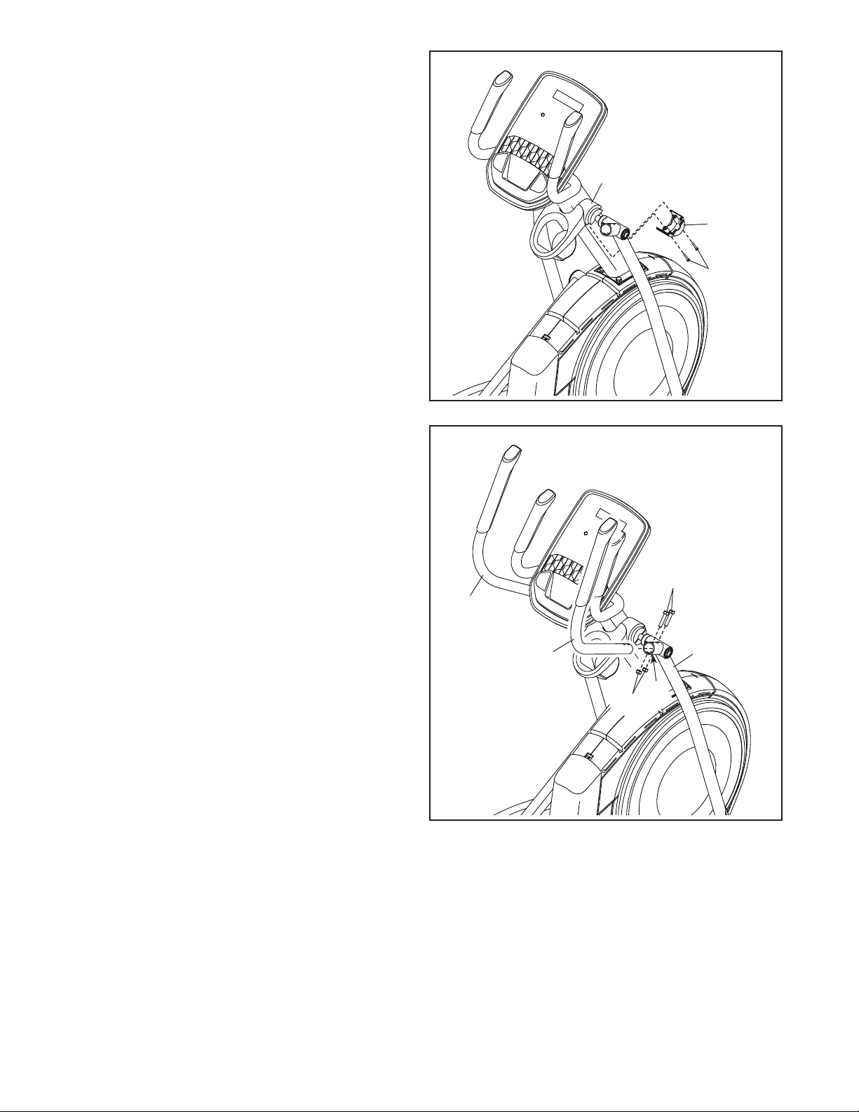
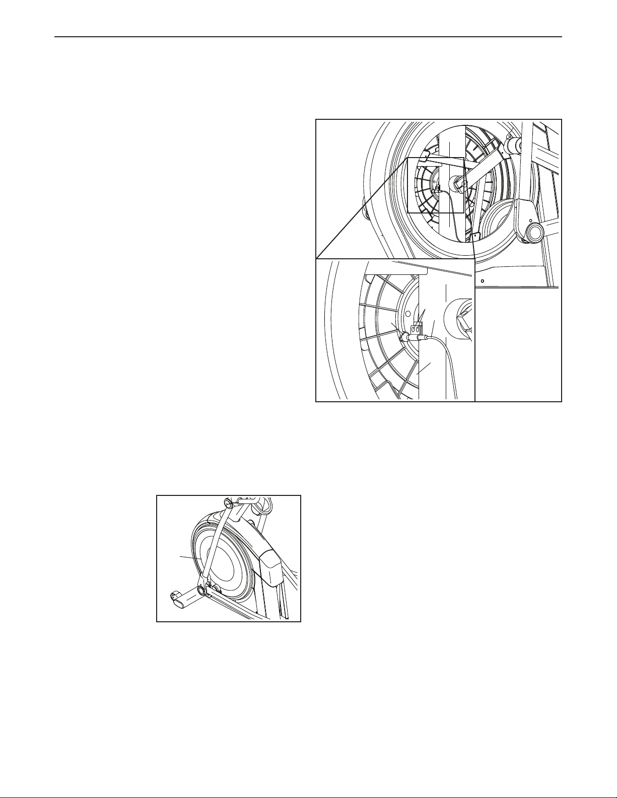
HOW TO ADJUST THE REED SWITCH
If the console does not display correct feedback, the
reed switch should be adjusted. To adjust the reed
switch, first unplug the power adapter.
Next, using a
standard screw-
driver, remove the
left Disc (71).
Locate the Reed Switch (38). Turn the Pulley (19) until
a Magnet (43) is aligned with the Reed Switch.
Next, slightly loosen the indicated two #8 x 1/2"
Screws (50). Slide the Reed Switch (38) slightly closer
to or away from the Magnet (43), and then retighten
the Self-tapping Screws.
Then, plug in the power adapter and rock the Pulley
(19) forward and backward just enough that the
Magnet (43) passes the Reed Switch (38) repeatedly.
Repeat these actions until the console displays correct
feedback.
When the reed switch is correctly adjusted, reattach
the left disc and plug in the power adapter.
71
43
19
50
38
MAINTENANCE AND TROUBLESHOOTING
28
HOW TO ADJUST THE DRIVE BELT
If the pedals slip while you are pedaling, even while
the resistance is adjusted to the highest level, the drive
belt may need to be adjusted. To adjust the drive belt,
first unplug the power adapter.
Next, locate the
Access Cover
(3) on the Right
Shield (74).
Remove the
M4 x 16mm
Screw (101) and
then remove the
Access Cover.
Next, locate
and loosen the
Idler Screw (89).
Tighten the Drive
Belt Adjustment
Screw (91) until
the Drive Belt
(113) is tight.
Then, retighten
the Idler Screw.
Then, reattach the parts that you removed, and plug in
the power adapter.
74
3
101
113
91
89
29
EXERCISE GUIDELINES
These guidelines will help you to plan your exercise
program. For detailed exercise information, obtain a
reputable book or consult your physician. Remember,
proper nutrition and adequate rest are essential for
successful results.
EXERCISE INTENSITY
Whether your goal is to burn fat or to strengthen your
cardiovascular system, exercising at the proper inten-
sity is the key to achieving results. You can use your
heart rate as a guide to find the proper intensity level.
The chart below shows recommended heart rates for
fat burning and aerobic exercise.
To find the proper intensity level, find your age at the
bottom of the chart (ages are rounded off to the near-
est ten years). The three numbers listed above your
age define your “training zone.” The lowest number is
the heart rate for fat burning, the middle number is the
heart rate for maximum fat burning, and the highest
number is the heart rate for aerobic exercise.
Burning Fat—To burn fat effectively, you must exer-
cise at a low intensity level for a sustained period of
time. During the first few minutes of exercise, your
body uses carbohydrate calories for energy. Only
after the first few minutes of exercise does your body
begin to use stored fat calories for energy. If your
goal is to burn fat, adjust the intensity of your exer-
cise until your heart rate is near the lowest number in
your training zone. For maximum fat burning, exercise
with your heart rate near the middle number in your
training zone.
Aerobic Exercise—If your goal is to strengthen your
cardiovascular system, you must perform aerobic
exercise, which is activity that requires large amounts
of oxygen for prolonged periods of time. For aerobic
exercise, adjust the intensity of your exercise until
your heart rate is near the highest number in your
training zone.
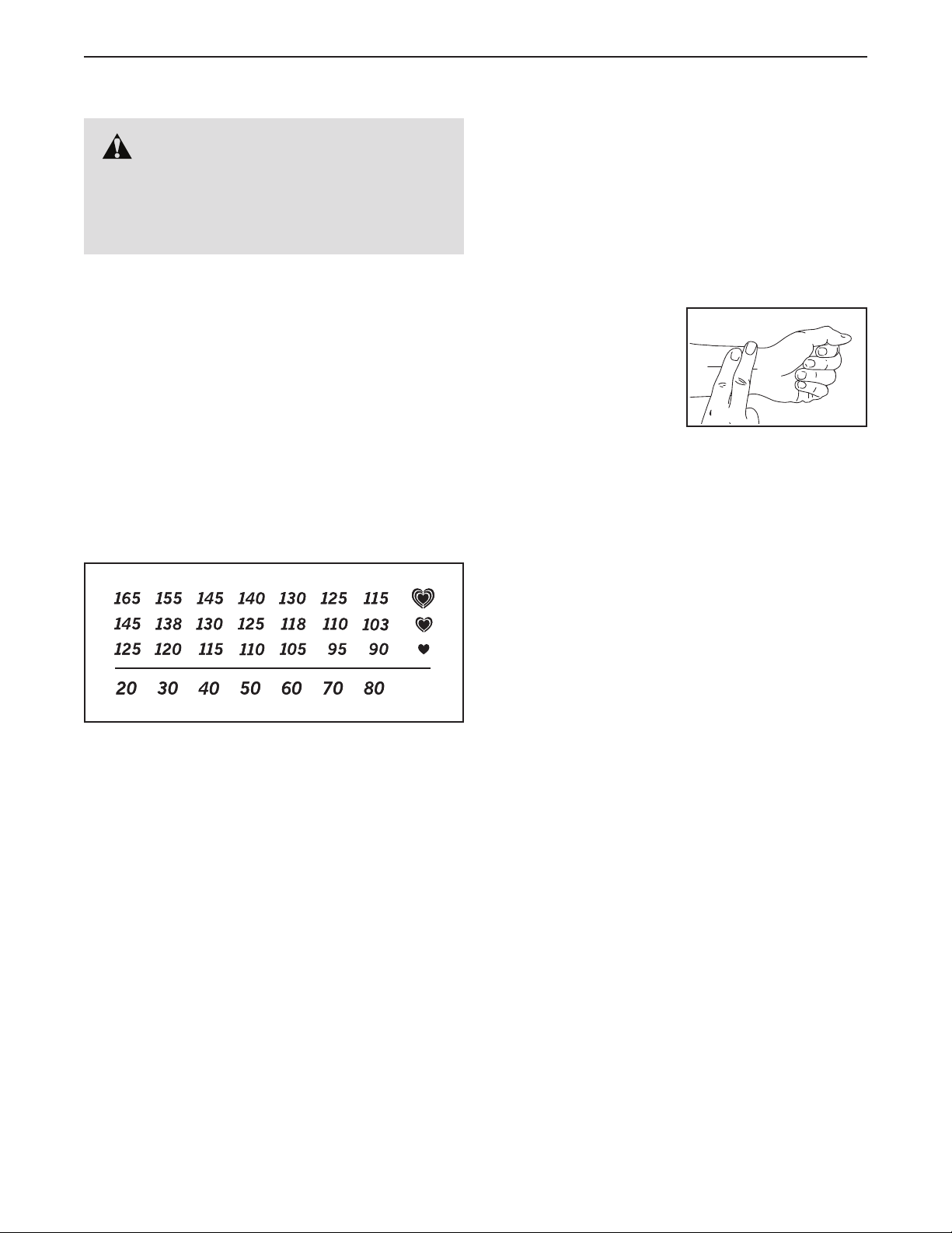
HOW TO MEASURE YOUR HEART RATE
To measure your heart
rate, exercise for at least
four minutes. Then, stop
exercising and place
two fingers on your
wrist as shown. Take a
six-second heartbeat
count, and multiply the
result by 10 to find your heart rate. For example, if your
six-second heartbeat count is 14, your heart rate is 140
beats per minute.
WORKOUT GUIDELINES
Warming Up—Start with 5 to 10 minutes of stretch-
ing and light exercise. A warm-up increases your body
temperature, heart rate, and circulation in preparation
for exercise.
Training Zone Exercise—Exercise for 20 to 30 min-
utes with your heart rate in your training zone. (During
the first few weeks of your exercise program, do not
keep your heart rate in your training zone for longer
than 20 minutes.) Breathe regularly and deeply as you
exercise; never hold your breath.
Cooling Down—Finish with 5 to 10 minutes of stretch-
ing. Stretching increases the flexibility of your muscles
and helps to prevent post-exercise problems.
EXERCISE FREQUENCY
To maintain or improve your condition, complete
three workouts each week, with at least one day of
rest between workouts. After a few months of regular
exercise, you may complete up to five workouts each
week, if desired. Remember, the key to success is to
make exercise a regular and enjoyable part of your
everyday life.
WARNING: Before beginning this
or any exercise program, consult your physi-
cian. This is especially important for persons
over age 35 or persons with pre-existing
health problems.
30
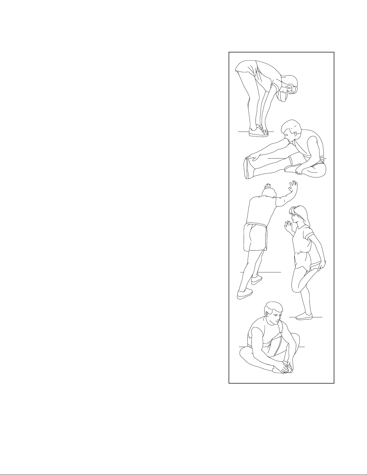
SUGGESTED STRETCHES
The correct form for several basic stretches is shown at the right. Move slowly as you stretch; never bounce.
1. Toe Touch Stretch
Stand with your knees bent slightly and slowly bend forward from
your hips. Allow your back and shoulders to relax as you reach down
toward your toes as far as possible. Hold for 15 counts, then relax.
Repeat 3 times. Stretches: Hamstrings, back of knees and back.
2. Hamstring Stretch
Sit with one leg extended. Bring the sole of the opposite foot toward
you and rest it against the inner thigh of your extended leg. Reach
toward your toes as far as possible. Hold for 15 counts, then relax.
Repeat 3 times for each leg. Stretches: Hamstrings, lower back and
groin.
3. Calf/Achilles Stretch
With one leg in front of the other, reach forward and place your hands
against a wall. Keep your back leg straight and your back foot flat on
the floor. Bend your front leg, lean forward and move your hips toward
the wall. Hold for 15 counts, then relax. Repeat 3 times for each leg.
To cause further stretching of the achilles tendons, bend your back
leg as well. Stretches: Calves, achilles tendons and ankles.
4. Quadriceps Stretch
With one hand against a wall for balance, reach back and grasp one
foot with your other hand. Bring your heel as close to your buttocks as
possible. Hold for 15 counts, then relax. Repeat 3 times for each leg.
Stretches: Quadriceps and hip muscles.
5. Inner Thigh Stretch
Sit with the soles of your feet together and your knees outward.
Pull your feet toward your groin area as far as possible. Hold for 15
counts, then relax. Repeat 3 times. Stretches: Quadriceps and hip
muscles.
1
2
3
4
5

31
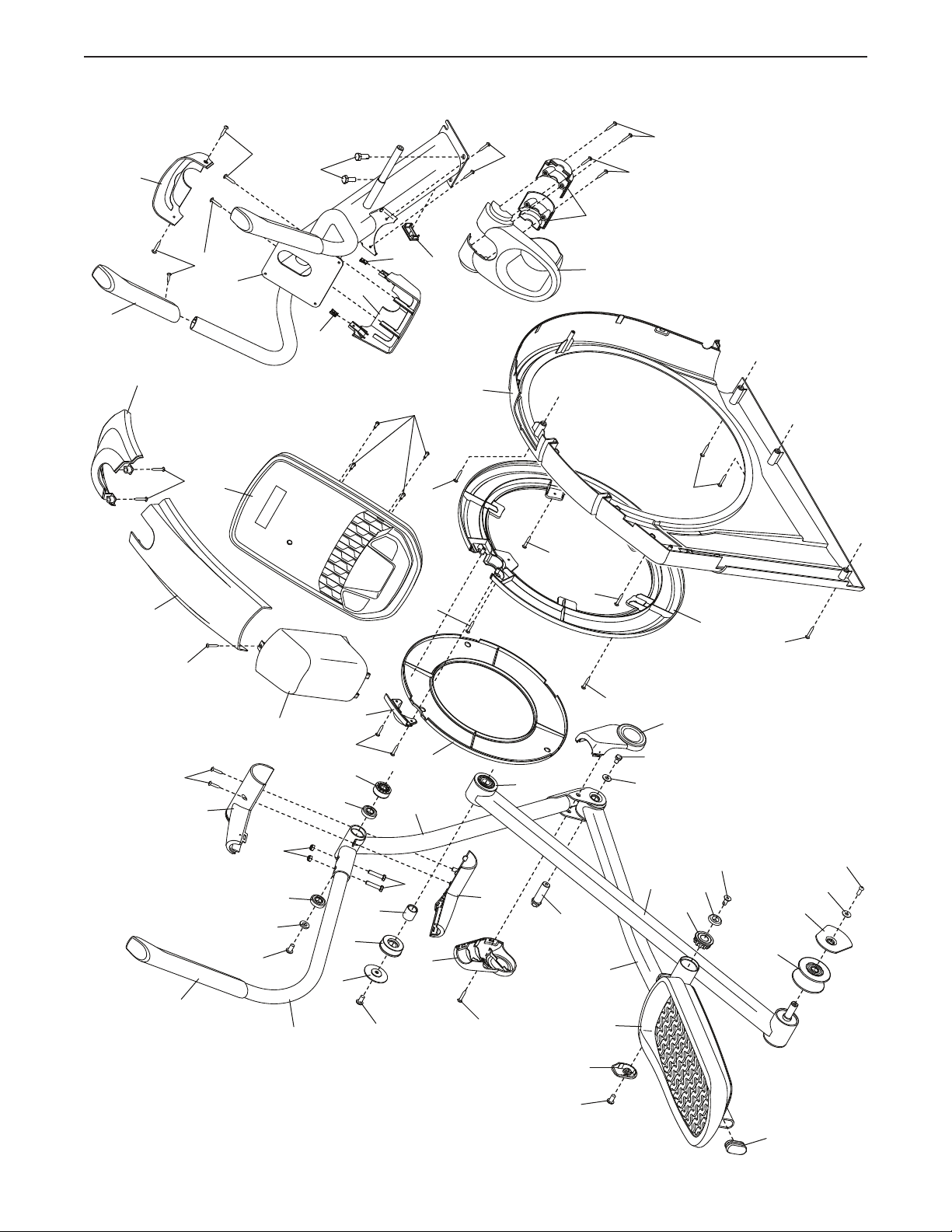
1 1 Frame/Ramp
2 1 Rear Stabilizer
3 1 Access Cover
4 1 Upright
5 6 M4 x 19mm Screw
6 1 Front Stabilizer
7 1 Console
8 2 Roller Guide
9 1 Crank Bearing Spacer
10 1 Rear Ramp Cover
11 1 Left Latch Handle
12 1 Right Latch Handle
13 1 Latch Button
14 1 Latch Bracket
15 1 Rear Stabilizer Cover
16 2 Track
17 1 Latch Pin
18 1 Crank
19 1 Pulley
20 2 Crank Arm
21 2 Adhesive Tape
22 1 Idler
23 2 Short Bumper
24 1 Small Leveling Foot
25 1 Resistance Motor
26 4 M10 Locknut
27 2 M10 Washer
28 1 Eddy Mechanism
29 1 Right Pedal
30 4 Stabilizer Cap
31 2 M10 x 16mm Screw
32 2 Roller Arm Bearing Spacer
33 2 Large Leveling Foot
34 2 Wheel
35 2 Clip
36 1 Idler Washer
37 1 Accessory Tray
38 1 Reed Switch/Wire
39 1 Reed Switch Clamp
40 2 Frame Bearing
41 1 Front Ramp Cover
42 1 Sleeve
43 2 Magnet
44 1 Left Pedal Arm
45 1 Left Roller Arm
46 1 Left Upper Body Leg
47 1 Left Upper Body Arm
48 1 Ramp Spring
49 1 Left Pedal
50 2 #8 x 1/2" Screw
51 2 Roller
52 2 Pedal Arm Cap
53 2 Axle Cover
54 2 Pivot Spacer
55 2 Retainer
56 4 Roller Arm Bushing
57 4 Pedal Arm Bearing
58 1 Right Pedal Arm
59 1 Right Roller Arm
60 1 Right Upper Body Leg
61 1 Right Upper Body Arm
62 2 Long Grip
63 2 Short Grip
64 2 Pedal Arm Axle
65 1 Right Arm Front Cover
66 1 Right Arm Rear Cover
67 1 Left Arm Front Cover
68 1 Left Arm Rear Cover
69 1 Right Leg Outer Cover
70 1 Left Leg Outer Cover
71 2 Disc
72 1 Left Leg Inner Cover
73 1 Left Shield
74 1 Right Shield
75 1 Center Shield Cover
76 1 Left Pedal Arm Side Cap
77 2 Crank Cover
78 2 Key
79 1 Front Console Cover
80 1 Rear Console Cover
81 2 Lower Tray Cover
82 8 M8 x 13mm Screw
83 1 Right Leg Inner Cover
84 1 M4 x 12mm Screw
85 1 Upright Grommet
86 2 M10 x 60mm Hex Bolt
87 1 Right Pedal Arm Side Cap
88 1 Idler Pivot Screw
89 1 Idler Screw
90 2 M6 Washer
91 1 Drive Belt Adjustment Screw
92 4 M10 x 25mm Screw
93 4 M4 x 12mm Flange Screw
94 2 M4 Nut
95 8 M8 x 20mm Screw
96 4 M8 x 45mm Bolt
97 2 M8 x 28mm Washer
98 2 M8 x 18mm Washer
99 1 Crank Pulley Spacer
100 4 Leg Bearing
Key No. Qty. Description Key No. Qty. Description
PART LIST
Model No. NTEL05621.2 R0621A

32
101 50 M4 x 16mm Screw
102 6 M8 Locknut
103 8 M6 x 12mm Screw
104 4 M10 x 115mm Screw
105 1 M4 x 25mm Screw
106 1 Bottom Ramp Cover
107 1 Crank Spacer
108 2 M6 x 13mm Screw
109 2 M10 x 60mm Bolt
110 1 Upper Wire
111 1 Lower Wire
112 2 M4 x 19mm Screw
113 1 Drive Belt
114 5 M4 x 10mm Machine Screw
115 2 M4 x 25mm Bolt
116 2 Disc Ring
117 1 Front Shield Cover
118 1 Rear Shield Cover
119 1 Power Adapter
120 2 M8 x 20mm Flat Head Screw
121 1 Latch Axle
122 1 Pin Spring
123 2 Outer Arm Bearing
124 2 M4 x 16mm Machine Screw
125 2 Snap Ring
126 2 M4 x 38mm Screw
127 2 Disc Bracket
128 1 Long Bumper
129 2 M8 x 22mm Washer
130 2 Inner Pedal Arm Bearing
131 4 #8 x 1/2" Self-tapping Screw
* – Assembly Tool
* – Grease Packet
* – User’s Manual
Key No. Qty. Description Key No. Qty. Description
Note: Specifications are subject to change without notice. For information about ordering replacement parts, see
the back cover of this manual. *These parts are not illustrated.
33
EXPLODED DRAWING A
4
35
85
35
37
81
54
63
71
79
73
75
80
101
101
101
101
101
92
124
5
101
101
101
101
117
116
118
101
101
101
5
131
131
7
46
52
45
44
47
49
51
56
55
123
130
68
62
67
70
72
76
77
95
95
120
82
97
100
100
8
127
82
129
96
102
98
95
64
32
101
Model No. NTEL05621.2 R0621A
34
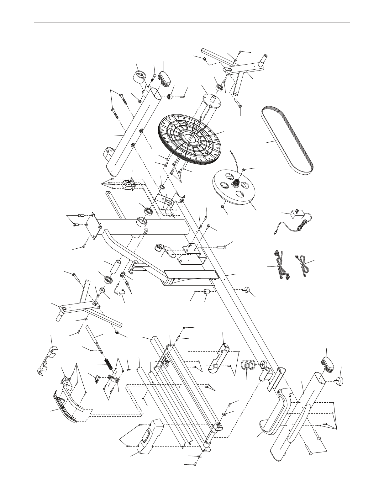
EXPLODED DRAWING B
26
26
39
107
125
125
121
110
119
111
6
10
101
2
14
16
18
13
15
106
17
20
101
114
114
101
94
28
30
22
33
41
43
43
48
88
93
31
31
89
90
91
27
27
108
113
84
115
102
101
102
30
21
16
1
122
101
36
20
34
104
26
109
112
23
82
82
25
78
86
78
86
92
90
108
38
105
128
50
104
1
24
12
11
19
101
114
9
40
42
99
40
Model No. NTEL05621.2 R0621A
35
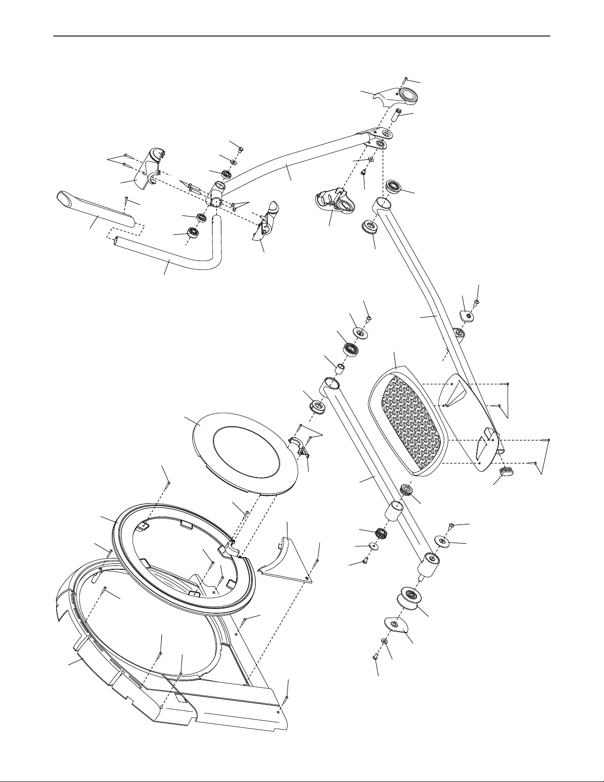
EXPLODED DRAWING C
74
124
5
5
116
131
131
5
101
95
127
52
29
58
57
57
103
103
87
56
55
120
56
51
53
95
98
95
8
71
60
101
61
66
62
65
69
83
101
126
126
101
101
101
3
82
96
129
101
102
82
97
100
100
54
64
59
130
32
123
77
95
Model No. NTEL05621.2 R0621A

Part No. 431400 R0621A Printed in China © 2021 ICON Health & Fitness, Inc.
To order replacement parts, please see the front cover of this manual. To help us assist you, be prepared to
provide the following information when contacting us:
• the model number and serial number of the product (see the front cover of this manual)
• the name of the product (see the front cover of this manual)
• the key number and description of the replacement part(s) (see the PART LIST and the EXPLODED DRAWING
near the end of this manual)
ORDERING REPLACEMENT PARTS
ICON Health & Fitness, Inc. (ICON) warrants this product to be free from defects in workmanship and
material, under normal use and service conditions. The frame is warranted for ten (10) years from the date
of purchase. Parts and labor are warranted for one (1) year from the date of purchase.
This warranty extends only to the original purchaser (customer) and is not transferrable. ICON’s obligation
under this warranty is limited to repairing or replacing, at ICON’s discretion, the product through one of
its authorized service providers. All repairs for which warranty claims are made must be preauthorized by
ICON. If replacement parts are shipped while the product is under warranty, the customer will be respon-
sible for a minimal handling charge. For in-home service, the customer may be responsible for a minimal
trip charge. This warranty does not extend to freight damage to the product. This warranty will automati-
cally be voided by the following conditions: (1) if the product is used as a store display model, (2) if the
product is purchased or transported outside the USA, (3) if any instruction or warning in this manual is not
followed, (4) if the product is abused or improperly or abnormally used, (5) if the product is modifi ed to alter
functionality or capability without the written permission of ICON, or (6) if the product is used for commer-
cial or rental purposes. No other warranty beyond that specifi cally set forth above is authorized by ICON.
ICON is not responsible or liable for the following damages: (1) indirect, special, or consequential dam-
ages arising out of or in connection with the use or performance of the product; (2) damages with respect
to any economic loss, loss of property, loss of revenues or profi ts, loss of enjoyment or use, or costs of
removal or installation; or (3) other consequential damages of any kind. Some states do not allow the
exclusion or limitation of incidental or consequential damages. Accordingly, the above limitation may not
apply to the customer.
The warranty extended hereunder is in lieu of any and all other warranties, and any implied warranties of
merchantability or fi tness for a particular purpose are limited in their scope and duration to the terms set
forth herein. Some states do not allow limitations on how long an implied warranty lasts. Accordingly, the
above limitation may not apply to the customer. This warranty provides specifi c legal rights; the customer
may have other rights that vary from state to state.
For warranty service, please call the telephone number on the front cover of this manual. Please be pre-
pared to provide the model number and serial number of the product (see the front cover of this manual).
ICON Health & Fitness, Inc., 1500 S. 1000 W., Logan, UT 84321-9813
LIMITED WARRANTY
IMPORTANT: To protect your fitness equipment with an extended service plan, see page 4.